PRE2022 3 Group7
Buoy-based Remote Autonomous Monitoring (BRAM)
Group members
| Names | Study | ID | |
|---|---|---|---|
| Max van Wijk | Electrical Engineering | 1736418 | m.h.o.v.wijk@student.tue.nl |
| David van Warmerdam | Electrical Engineering | 1714171 | d.s.v.warmerdam@student.tue.nl |
| Luka Tepavčević | Electrical Engineering | 1720996 | l.tepavcevic@student.tue.nl |
| Bob Verbeek | Biomedical Engineering | 1752510 | b.m.verbeek@student.tue.nl |
| Yu-Hsuan Lin | Computer Science | 1672363 | y.lin1@student.tue.nl |
| Saskia ten Dam | Psychology and Technology | 1577328 | s.e.t.dam@student.tue.nl |
Separate pages of important information
Logbook page: This page contains the logbook, how much time everyone spend per week, and the general planning of group 7.
Interview page: This page contains the interviews that have been conducted by group 7, a summary of each interview, as well as some small descriptions of the interviewees to give some background.
Weekly research and activities : This page contains, for every week of the project, a summary and overview of the research done by group 7. The contents of the page have been structured in chronological order. The important content of this page that the report does not elaborate on include:
- The research and references of the brainstorming sessions for project ideas.
- How a diver would install the buoy (this is spread out over multiple sections instead of one specific paragraph).
Introduction
The ocean is the biggest ecosystem on earth. It is essential for human existence on earth. The ocean provides food, energy and water and is essential to human existence on earth[1]. However the ocean has several threats. Between 2009 and 2018, about 14 percent of the ocean’s coral reef was lost[1]. Temperatures are rising, and acidification is occurring which are big threats to coral reefs. The rising carbon dioxide rate is critical as the corals don’t have the capacity to adapt fast enough. They have a long lifespan and therefore the adaptation of coral reefs is a slow process[2]. Coral reef extinction is a big threat for the biodiversity in the ocean and therefore the whole earth's ecosystem.
Furthermore, for on land, coral reefs protect the coastlines from powerful waves and storms. Additionally, coral reefs bring about many jobs, and therefore many people rely on coral reefs for their lively hoods.
Thus, saving coral reefs are of great importance. The urge to protect this has risen. In 2022, the united nations made a goal together. “The 30x30 goal’ By 2030, 30% of the ocean needs to be protected[3]. To obtain this goal, a lot of data is needed and efficient research.
For this research it was decided to focus on the Great Barrier Reef due to the fact that it was one of the most threatened coral reefs in the world.
Problem Statement
After having done the above mentioned research into coral reefs, their importance, how we can defend them, and how they are currently protected, we have come up with a method of supporting the current researchers by creating a new method of data gathering. We have designed a buoy based sensing system that is comprised of a diver, which is able to move up and down through the water, and a buoy, to where this diver is attached. This buoy would be able to carry any type of sensor that a particular researcher may desire, and measure a particular parameter at a self specified depth. The buoy would be able to send this data back to the researcher in real time, removing the need for any human intervention that could disturb the coral reef. These disturbances, mainly caused by boat engines, are a large problem for the marine inhabitants of these coral reefs, as they increase the chance of body malformations, development issues or disorientation to the fish that are present[4].
Not only does this new design add a new data collection system to the already existing methods of data gathering in coral reefs, solving, or at least lessening the impact of the gap in reliable and human free data in coral reefs. But it also paves a path for new improved design options that could build of off our buoy based remote sensing design. Because of these reasons, we believe that our design is able to solve the aforementioned problems.
USE Analysis
As the project is focused around the notion of USE (user, society, enterprise), it is of great importance to start by connecting to the future users of our product before finalizing the design. We have done this by interviewing marine biologists and researchers who are closely related to the topic of coral reefs. The interview page shows the questions asked, as well as a quick summary of the interviewee and the interview itself.
Users
As mentioned previously, the main users of the buoy, and subsequently the first party stakeholders, are researchers. More specific marine biologists who are focused on coral reefs. Furthermore, the scientific divers themself who have to install the buoy and do some checks.They are the foremost people who have the means and desires to stop the deterioration of coral reefs. Therefore, they are the people who will most likely be the ones using our design. They will benefit from the automation of data collection. From the interview, the automation of some types of their data collection will make their research more efficient.
These researchers have also been used as the main source of information when it comes to the overall design of the product, not only by reading articles about the already present research, but also by interviewing them and asking specific questions regarding the design of the buoy. As they’re desires are sometimes different, regarding different types of research. From the 3 interviewers, 2 of them collected data for research purposes. 1 of them did restoration work regarding coral reefs. They used different parameters for different areas. Therefore, 1 of the advantages they mentioned was flexibility in sensing. Thus, in this project the focus will be laid on the hardware, so types of sensors can be decided on by the researchers.
Other stakeholders of the design include funders of our design, second party climate researchers who use the data, people living close to coral seasides and the government. Who will invest in these buoys is yet undetermined. However some of the stakeholders can be expected to fund. With the UN goals that are made there is movement from government funding. The ‘Reef Trust Partnership’ is a six-year grant of 444.4 million dollars on behalf of the government of Australia, the Reef Trust funding and the Great Barrier Reef Foundations. This is a cooperation of the government and a fund where everyone can donate money[5]. They might be willing to invest in efficient research and therefore our buoy. Other climate researchers will benefit from the increase in accurate data. Finally, inhabitants of the seaside coral reefs will be able to keep their businesses alive, be they fishing or tourism.
Society
Our buoy based remote sensing technology would affect society in a positive manner. More reliable data is able to be gathered from one of the most important oceanic locations on the earth. This, in turn, will make it so that researchers are becoming more capable in creating more realistic predictions about coral reefs in general. This research could help protect and restore the coral reef giving these reefs a higher chance of prolonged, or even lasting, survival. This in turn has positive effects.
Coral reefs are natural wave stoppers. This means that, as global warming and rising sea levels become more and more extreme, these coral reefs will stay as they are and help prevent some of the damage that these catastrophic events can cause, helping society as a whole.
Furthermore as discussed in the introduction, saving coral reefs will help to protect biodiversity. And as mentioned, keeping the ocean intact will provide food, water and energy for humans. Therefore this will affect society.
Enterprise
Every year approximately 2 million tourists visit the Great Barrier Reef in Australia.
The great barrier reef is the largest economic contributor to the Australian economy and marine tourism provides over 60.000 jobs[6].
The Reefs' health is therefore important for the economy of Australia and the companies that work in the tourism business. As explained before the main goal of the buoy will be to provide research to support protecting the reef. Therefore these companies will indirectly benefit from the buoy.
Initial research
First of all, it is important to have a better understanding on what factors affect coral reefs in what way. Therefore the following section will focus on threats caused by both humans and natural causes and how these threats impact coral reefs.
Threats on coral reefs
Threats caused by humans:
- Climate Change (the majority of coral reefs thrive in temperatures between 23 and 29 degrees[7] with few reefs being able to tolerate temperatures as low as 18 degrees and as high as around 40 degrees). Therefore with how the average temperatures are increasing, the ideal temperature for most reefs would be exceed on a more regular basis. This can then cause ‘coral bleaching’ which appearance wise makes corals lose their colour and turn totally white. This in turn makes the corals unhealthy and ‘stressed’ which also would have an impact on the fauna that rely on corals to survive.
- Unsuitable fishing practices (such as over-fishing and hunting endangered species). This can have disastrous effects on the food chain (ecology of the environment). For example if a certain type of fauna is explicitly hunted, and that animal is somewhere high in the chain, this can lead to some of the animals lower in the food chain to start multiplying faster which can totally offset the ecosystem as there are not enough predators due to hunting.
- Land-based pollution. This includes stuff such as coastal development and agricultural runoff. Coastal development likely directly destroys the environment that is being ‘developed’ whereas agricultural runoff is when sediments such as soil go into water bodies where they are not supposed to be. This is because the composition of such sediments can be harmful to the coral, leading to diseases and etc, as the sediment can contain things such as fertiliser, microorganisms and some kinds of nutrients that the corals do not need or can not handle.
- Damage from ships (such as grounded ships[8] ) can destroy large amounts of coral that took hundreds of years to form. Furthermore overtime more harmful/toxic substances such as paint and fuel from ships can leak as the ship slowly degrades and such poisoning the corals.
Threats caused by nature:
- Tropical Storms, especially larger storms have a much higher likelihood of physically damaging the corals, especially the coral structures nearer the ocean surface.
- Diseases, as corals are also living being, and also generally classify as animals, as such they are susceptible to diseases naturally as well as unnaturally that has been discussed previously.
- Invasive species, when fauna that is not native to that area comes there and starts to occupy/ take a lot of resources from the fauna that originally lived there.
Now that we know why coral reefs are in need of saving, giving us a motive for our bouy-based design concept, it is of great importance to elaborate what criteria the buoy should follow and what should be the focus of this project. Furthermore, it should be stated why the buoy based design would be better then the current state-of-the-art that is used to measure and collect data in coral reefs, or why our initial design idea would benefit the researchers of today.
General MoSCoW List
Below, a table of the overall MoSCoW table is shown. This table is not specifically for what we as a group will be focusing on, but how we would envision the design as a whole. Of course, this does not bring much benefit to our project, but could help further projects build on top of this buoy based project.
| Must Have | Should Have | Could Have | Wont Have |
|---|---|---|---|
| (Salt) water proof | The ability to change the depth of the diver (The diver contains the sensors) | The ability to move the “base” | The diver can clean the coral reef at the same time |
| The ability to float on water (The base of the buoy) | The ability to transmit data directly to some external server or computer in real time | The ability to share data with other buoys of the same type (swarm technology) | the ability to reach measuring depths for outer reefs (reaching depths of around 2000m) |
| High Visibility to avoid collisions with boats | An energy source to power itself (Self-powering) | Be easily accessible for repairs and other things which might need to | Diver can move actively through the water |
| To be able to reach the depths of the inshore coral reefs | Some way of keeping the buoy in the approximate same geographical location | Be able to reach measuring depths of around 100m for inshore reefs. (10bar) | Cable connection with base is made of glass fibre |
| A way of avoiding damaging coral structures | The diver should be able to dive down straight below the base (perhaps not straight down but parallel to anchor) | Be made of renewable materials | |
| The ability to configure and change which sensors can be put onto it so that the users can change out the sensors based on what they might want to specifically look at | Be build as cost effective as possible | A way for barnacles and others sealife don’t attach themselves to the device | |
| Provide long term monitoring data | |||
| Should be able to carry sensors (the weight should be accounted for) | |||
| The buoy has a battery that in no way can harm its environment |
Focused MoSCoW list
The following MoSCoW list illustrates the aspects of the previous MoSCoW list that we, as a group, will be focusing on for this project. As our previous MoSCoW list looked at too many different aspects of the design to be changed, which would be too much for the limit.
| Must Have | Should Have | Could Have | Wont Have |
|---|---|---|---|
| (Salt) water proof | The ability to change the depth of the diver (The diver contains the sensors) | The diver can clean the coral reef at the same time | |
| The ability to float on water (The base of the buoy) | Some way of keeping the buoy in the approximate same geographical location | the ability to reach measuring depths for outer reefs (reaching depths of around 2000m) | |
| To be able to reach the depths of the inshore coral reefs | The diver should be able to dive down straight below the base (perhaps not straight down but parallel to anchor) | Cable connection with base is made of glass fibre | |
| A way of avoiding damaging coral structures | Should be able to carry sensors (the weight should be accounted for) | Diver can move actively through the water | |
| The ability to configure and change which sensors can be put onto it so that the users can change out the sensors based on what they might want to specifically look at |
Solution Encyclopedia
Now that a focused MoSCoW table has been made, it is important to establish one or multiple solutions for each must-have and should-have. For this, a solution encyclopedia has been made to illustrate all possible solutions for every problem.
| Problem | Possible solution(s) |
|---|---|
| (salt) water proof |
|
| The ability for the base to float on water |
|
| Being able to reach inshore depths |
|
| The ability to change the depth of the diver |
|
| Keeping the buoy in the same aproximate location |
|
| The diver should be able to dive down straight below the base |
|
| Should be able to carry sensors of different varieties |
|
Current state-of-the-art versus our idea
There are currently three main methods which scientists use to measure and/or monitor coral reefs, its inhabitants and the waters in and around the coral reefs. We will be going over each of these methods, explain how they work and what they focus on, and how our initial idea would be better in certain areas then the mentioned method.
Satellite imagery
Satellite imagery is currently one of the most used methods for measuring surface level water parameter, which is not only used in for coral reefs, but for the entire ocean surface. These satellites can either function based on wavelength reflections from the ocean surface, from which specific water parameters are able to be derived. They also have the ability to make high quality images of the ocean surface. Some variables that can be obtained with the use of satellites include:
- Depth and depth variations[9]
- Temperature[9]
- Oceanic currents[10]
- Ocean surface color[11]:
- Chlorophyll-a coverage
- Different types of phytoplankton
- Coloured dissolved organic matter (CDOM)
There are, however, some disadvantages that come with the use of satellites to measure data. To begin, satellites use a method of top-down monitoring. This results in the effect that variables that are being measured will only be accurate for heights of up to 20 meters in depth, but have the clearest resolutions for depths of less then 5 meters.[12]
Human divers
A second method of measuring the oceans, and especially coral reefs, is with the use of human divers. Human divers have the advantage over satellites that they are able to measure variables like temperature, salinity or turbidity in depths of more then 20 meters, giving this method an edge over satellite monitoring. Another pro of using a human diver is that, due to being under the water and up close to the coral structures, clearer photographs are able to be made of, for example, decaying coral structures as opposed to satellite images. Furthermore, divers are able to physically analyse and/or take samples of these coral structures with them to further analyse the overall structure in, for example, a laboratory.
One of the downside to using human divers over satellites is the fact that humans are not able to stay underwater for prolonged periods of time due to their need for oxygen tanks to survive in these depths. This makes it so that no long term monitoring is possible with this method. Another drawback is that these dives can be very costly. Not only is the equipment needed for the dives at least a 1000 euros[13], but the licenses needed for these dives can also be fairly expensive and increase in amount the deeper the license allows. This, of course, does not even take into account the costs of traveling to the specific location one wants to measure, which, depending on the locations, can also rack up easily.
When comparing our initial buoy idea to human divers, we can immediately see that they are not targeted at the same ocean parameters. Human divers mostly focus on photographs and physical sampling, while our idea would mostly focus on water parameters around the coral reefs, although human diver are, of course, able to measure these parameters as well. Our idea does have the upper hand when it comes to data gathering over longer time periods, as, just like satellites, our buoy would be able to measure the water over multiple weeks, possibly even longer.
Boat-based sensors
A final method that is currently being used to monitor coral reefs and its surrounding waters is with the use of boats. These boats are able to either lower sensors underwater, or use sensors which are already attached to the bottom-side of the boat, to gather information about the seas. The most common and widely used sensors for these boats are sonar sensors[14]. These sensors, in combination with satellites, are able to accurately map out ocean floors and, to some extend, simple coral structures. These boats equipped with sensors have the advantage over human divers when it comes to the time it takes to gather data. Where a simple dive can take up to multiple hours to complete, boats are able to collect and even process the data within an hour[15].
However, boats still have hefty costs of hundreds, if not thousands of euros[15], making this method less affordable for the average researcher. Another downside of using boats to analyse coral reefs is that boats come with the added noise pollution from, for example, the motor. This noise pollution could result in an increase in the stress levels and an increase in hearth rate for the fish living in these coral reefs[16], which, in turn, could result in a decrease in fish populations living in and around these diverse reefs.
From a global view, boat-based sensors and our initial idea of buoy-based sensing are quite similar, as they both include sensors being dropped in a specific location for a period of time. Our idea, however, would be able to stay in the specific location for longer periods of time because, just as with the human divers, boats still require humans to operate, making day long monitoring sessions less likely to occur. Moreover, our idea removes the moving-ability of the boat and, in turn, trades this for a tremendous reduction in noise levels produced.
Other buoy-based sensors
There do already exist some buoys equipped with sensors to sense shallow marine environments, such as one made by the Technical University of Cartagena[17]. This buoy, and others of the same variety, all use a similar technique of attaching a couple of sensors to the buoy and letting these sensors drift in the water. We wanted to improve upon this design by first making it so a researcher can choose for themselves what types of sensors they would want to equip the buoy with. This would, in turn, increase the use range of our buoy, while not increasing the weight of the overall buoy by added all of the other redundant sensors as well. Furthermore, our buoy will have the ability to move the sensors to a specific depth which will be able to be manually chosen by the researcher. This should result in the buoy being able to be used in not only shallow reef areas, but also deeper parts of these coral reefs.
The Design of the Buoy
Design Process
The main focus of the design process was to design a diver that would be attached to a buoy which would be lowered through the water whilst carrying sensors to be able to monitor the water quality at different depths.
Anchor
The original ideas for the buoy and diver included an anchor as it was found that anchors were the most suitable for deploying the buoys such that they would not be swept away by tides and wind. Furthermore it was considered to be the easiest and most efficient way to deploy a buoy. But whilst doing further research and consulting with interviewees that could have been possible users, it was found out that for coral reefs, anchors were not as viable of an option due to how destructive the process on anchoring would be. Furthermore in many reefs anchors are also banned.
With this new found knowledge, the original designs were further developed to be suited to being deployed in coral reefs. Alternatives were found to replace the anchor, with the most promising alternative being mentioned by one of the potential users, which was the use of a reef hook. The only issue for the designs was that one reef hook would not be sufficient to properly anchor the buoy as such multiple reef hooks were included in the designs. Another issue which the reef hook introduces is the need to find the right structure to hook it too, this problem was also pointed out by one of the interviewees. If the coral structure which the buoy is hooked to, is too weak, the buoy could damage the coral if the coral could not hold the buoy do to the buoy pulling more than the coral can handle. Using these hooks for other structures on the ocean floor removes this issue in some way, however if the structure would not be strong enough, the buoy would be lost. Also this structure could not be heavy enough or mounted strong enough to the ocean floor which could result in the buoy dragging this over the ocean floor damaging the coral.
The final option was using a concrete slab, this was recommended by one for the researchers who was interviewed. This concrete slab would be heavy enough as it would be designed to withstand the forces from the buoy easily. This slab would be dropped carefully in the ocean by a boat or either a balloon attached to the slab, diver will carefully place the slab so it goes to the correct place and does not damage the coral structures in the immediate vicinity.
Cables/chains
For the connection between the buoy and the concrete slab, the choice is between using chains or cables. As chains are in general stronger and can be made of material which are good against the salt water, such as stainless steel, this was chosen over cables. State of the art research shows that most often a combination between chains and cables are used in various buoy, but buoys do exist with just a chain or just a cable. The chain used in the final design have a height of 0.1 m, are 6 cm wide and the chain links are 1 cm thick.
Winch
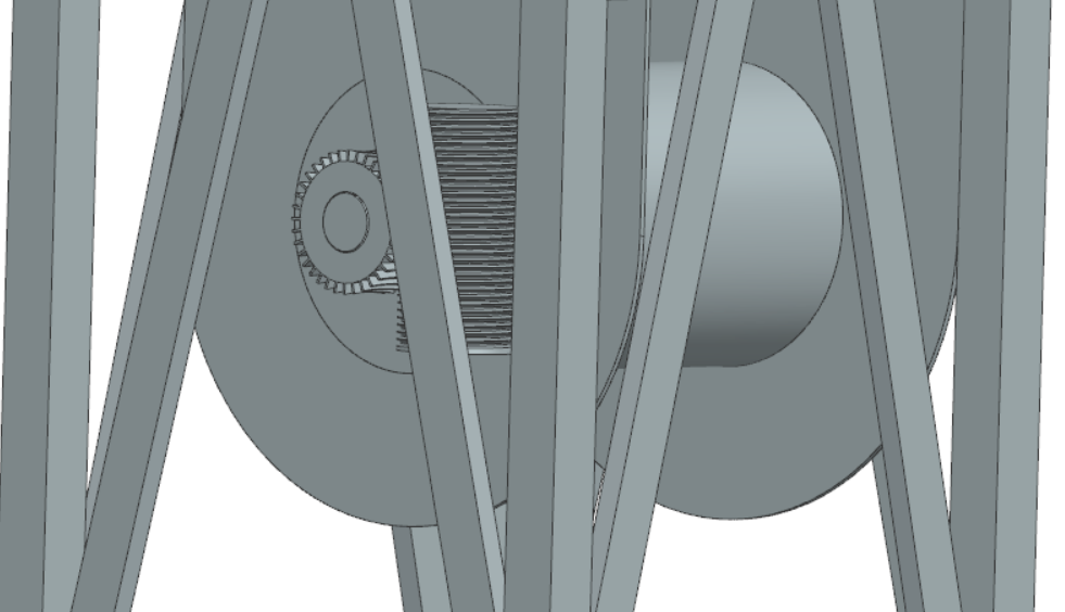
In order for the diver of the buoy to be controlled from going up and down, a mechanical mechanism needed to be used which would provide this specification. A winch was the perfect fit. It would lift the diver up and lower it down in a simple way. This winch can then be controlled by a high torque motor, such as a stepper motor, in order to handle the weight of the diver. Adding a gearbox would be applicable depending on the weight of the diver and torque of the motor.
Diver
The diver needs to be designed correctly as it needs to be able to dive down to the specified depth without too many problems. It should also fit the sensors the user would require.
One of the most important things is that it should dissipate as less as water to decrease buoyancy for which the diver can easy propagate the water. Knowing Archimedes principle: the buoyancy force is equal to the weight of the water the object is dissipating - the diver should be heavy enough and shape does not matter for this, only the density.
To know what the volume and mass of the buoy should be the following equations are used:
Fg=m g[18] ,
where Fg is the gravitational force working on the object, m is the mass of the object and g is the gravitational acceleration, and
Fb=ρfluid V g[18] ,
where Fb is the buoyant force, ρfluid is the density of the fluid the object is in and V is the volume of the object which is submerged in the water. As V would be the full volume of the diver (as it is fully submerged) the following equation can be derived:
m/V=ρfluid,
this is the case of an equilibrium case. So as long as m/V is greater than the density of the fluid, the diver will sink.
To know the density of the water more information is to be known in order to determine this, as the density of sea water is a function of the temperature, depth (thus pressure) and salinity. Average sea specifications of the great barrier reef:[19]
- Water depth is 30 meters on average in the GBR; which is around 3.5 bar; account for 5 meters of error.
- Salinity level around 35 g/kg
- Temperature averaged between 21-28 (celsius); 24.5 on average
Thus, the density results in a value of 1023.65 kg/m3 [20]
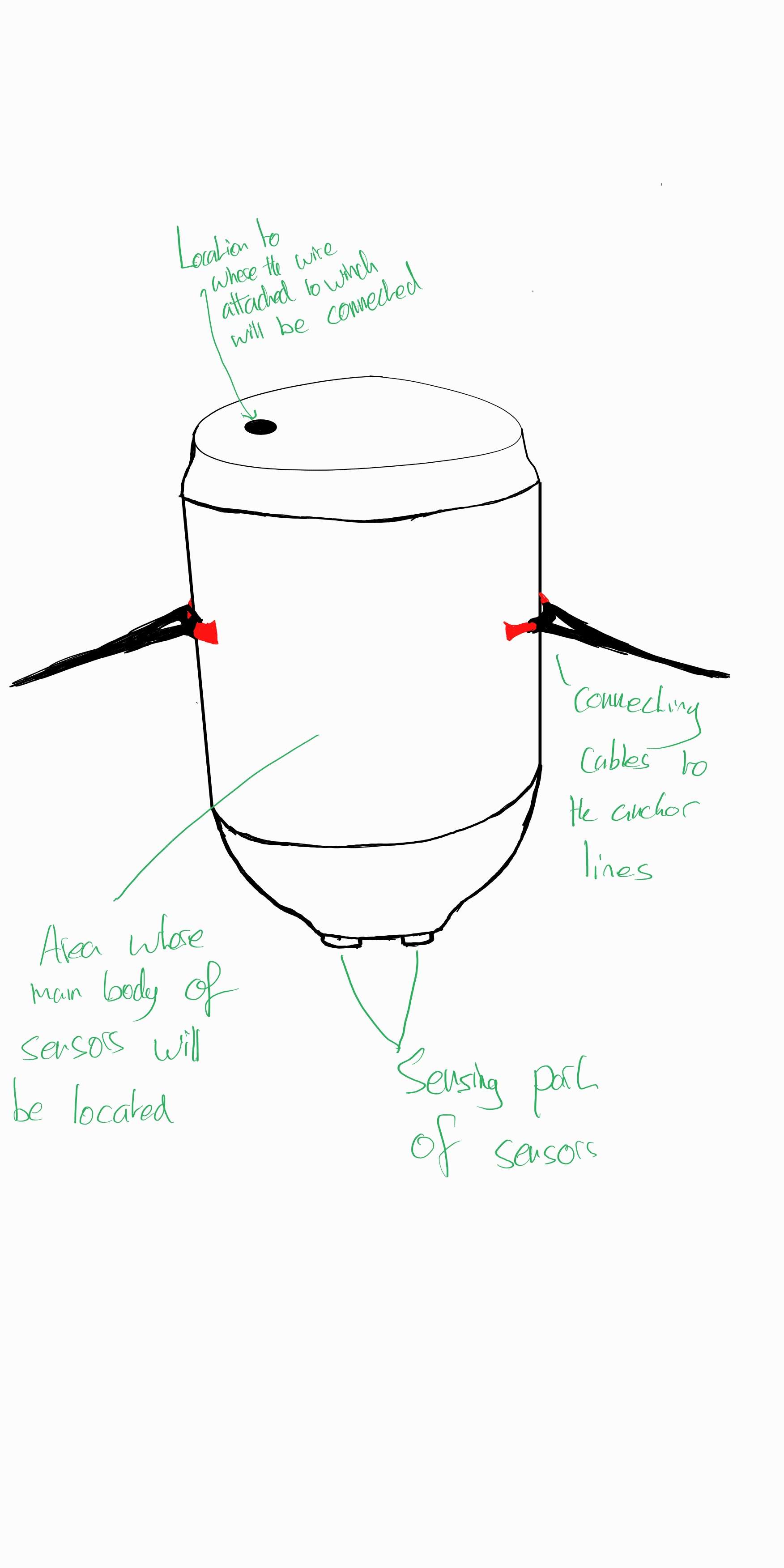
Now, the mass and volume of the diver need to be determined. An important constraint for the buoy is that it should be big enough for multiple (multipurpose) sensors. Two multipurpose sensors were chosen for reference. Their dimensions and weight are: (length x diameter mm): 295x38,5; 330g [21] ; 300x35; 410g [22], these sensors are also mention in the weekly research and activity in the state of the art. A distance of 20mm needs to stick out to make sure the measurements are able to be taken. The probes will be in the diver and data from these probes will be sent to the buoy, so having only the probe dimensions as reference is sufficient. With these constraints given as reference, multiple design where made:
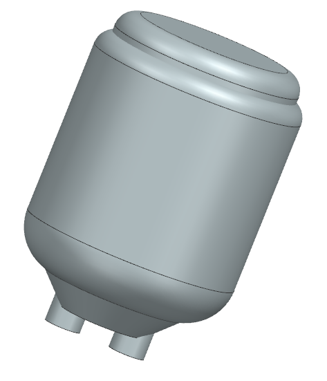
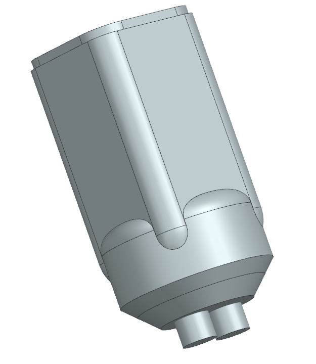
Diver design 1: as for all models, the 2 cylinders seen near the end are the multipurpose sensors taking for reference as explained earlier. This design is simple, but gives plenty of space for more and other sensors if needed. The shape however, is not particularly hydrodynamic . (Total volume = 0.01110 m3; Material volume = 0.007568 m3)
Diver design 2: this design was more focused on space rather than hydrodynamic. Thus it gives sufficient space, but the diving could be slower than the other designs. (Total volume = 0.002397 m3; Material volume = 0.006899 m3)
Diver design 3: this design was more focused on hydrodynamic rather than space. Thus it gives it will dive down fast, but with rather less space than the other designs. (Total volume = 0.01035 m3; Material volume = 0.004378 m3)
-
Diver design 1
-
Diver design 2
-
Diver design 3
In order to determine the mass, a material should be chosen. The following specifications where determined when solving this problem: it should be heavy enough with the volume given of the diver; it should be resistant against salt water; it should be easy to manufacture if the design is rather complex; it should withstand the pressure (also due to thickness of the diver).
Possible material include metals and plastic [23]:
- Metal: Brass, bronze, 316 stainless (also known as A4 stainless) steel, titanium are all good options.Titanium is the best metal to use, but is expensive
- Plastic: POM Delrin (a brand name of acetal)
- 3D printed plastics: difficult to make waterproof
Computer Numerical Control (CNC)[24] machines can be used to create complex metal part. These machines carve structures into metal, thus it can provide specific parts needed in our model, but not entire structures. With the use of Direct Metal Laser Sintering (DMLS)[24], complex 3D metal structures can be developed. Thus stainless steel can be used even though our models are not strictly simple structures.
Due to the simple shape and space given, design 1 was chosen out of the design. With the density of stainless steel 316 being 7980 kg/m3 [25] , this material was chosen. With this, the final weight of the diver is (0.007568 * 7980) 60.39 kg and with sensors, 61.13 kg.
Check:
m/V>ρfluid;
m/V = 61.13/0.01110 = 5507.445 kg/m3;
ρfluid = 1023.65 kg/m3;
The diver will be able to dive down.
Base
State of the art research about buoys resulted in a general shape of a cylinder with rounded edges. Even though the size of the buoy couldn't really be determined by the state of the art research using some approximations for our design resulted in the following dimensions for the base cylinder: A diameter of 1.5 m and a height of 0.6 m. Using this the volume of the main body of the buoy is 1.06 m^3. The weight can then be calculated by using the density of material used for its construction, our research sadly didn't result in a specific material that is used in the construction of buoys making it impossible to accurately calculate the final weight of the product.
Initial Designs
Idea 1
Concept:
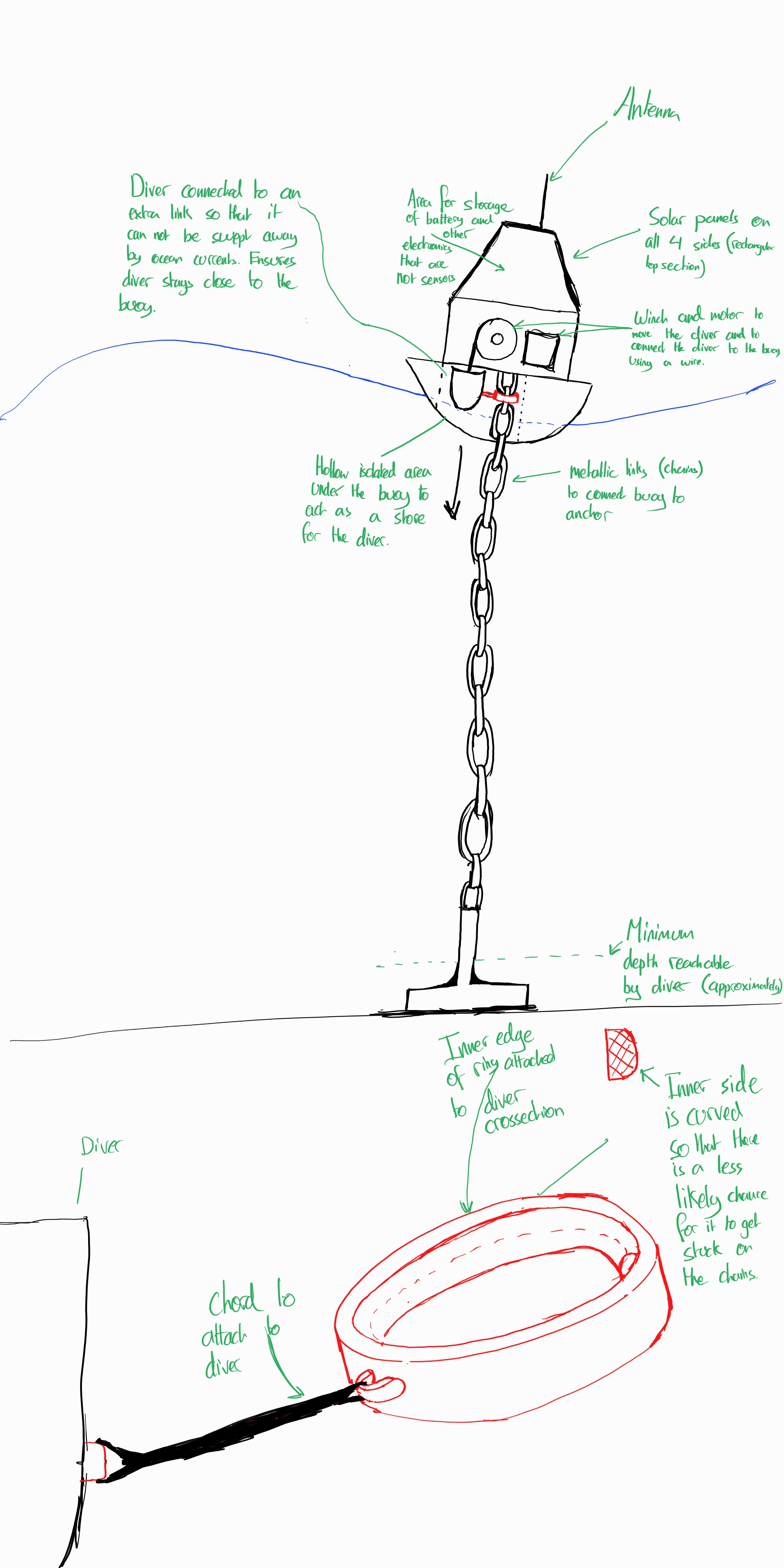
This initial concept shows a buoy that is connected to an anchor by chain. Most of the electronic equipment which does not include the different sensing equipment would be within the main frame of the buoy above the water. Whereas the sensors would be situated within the diver which would be lowered into the water to take measurements at different depths. The diver would be separate from the buoy but it would be connected to a winch within the buoy so that the depth of the diver can be changed accordingly. The diver is linked to the anchoring line by means of a shackle type object. This would prevent the diver from being swept away by currents.
Flaws:
- Uses an Anchor, in many Coral Reefs, anchors are banned because they would destroy large amounts of coral that would take many years to regrow.
- Chains have to be longer than the average depth where the buoy is situated due to the tides. This could mean that the chains could potentially also destroy the corals around the anchor.
- Shackles could potentially get stuck between the chain links if the chains are too large.
Idea 2
Concept:
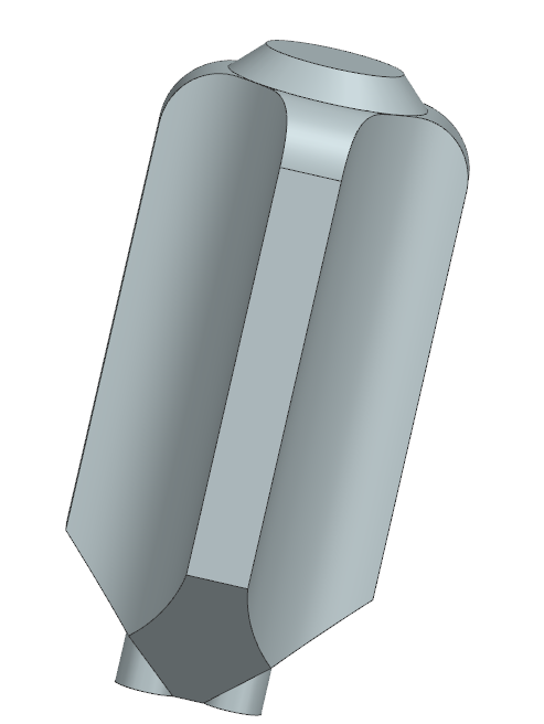
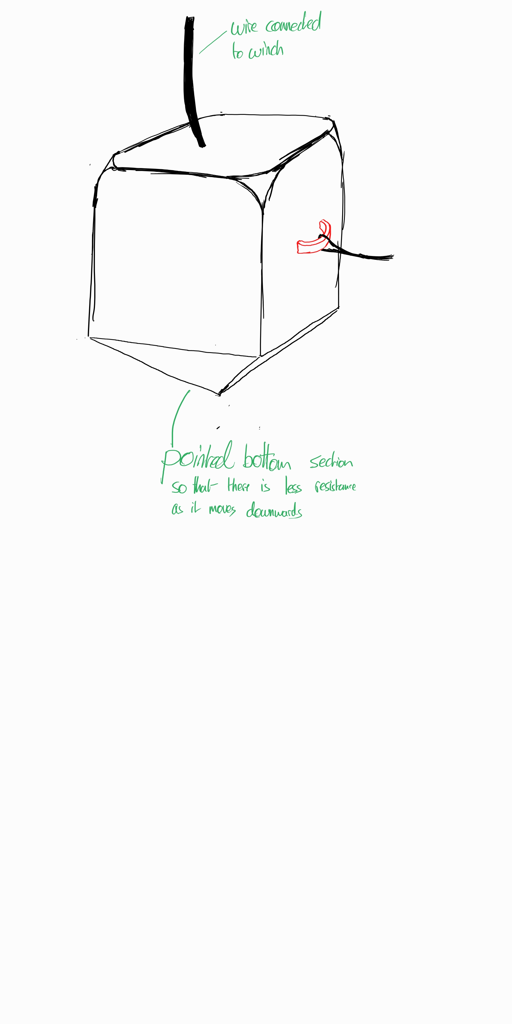
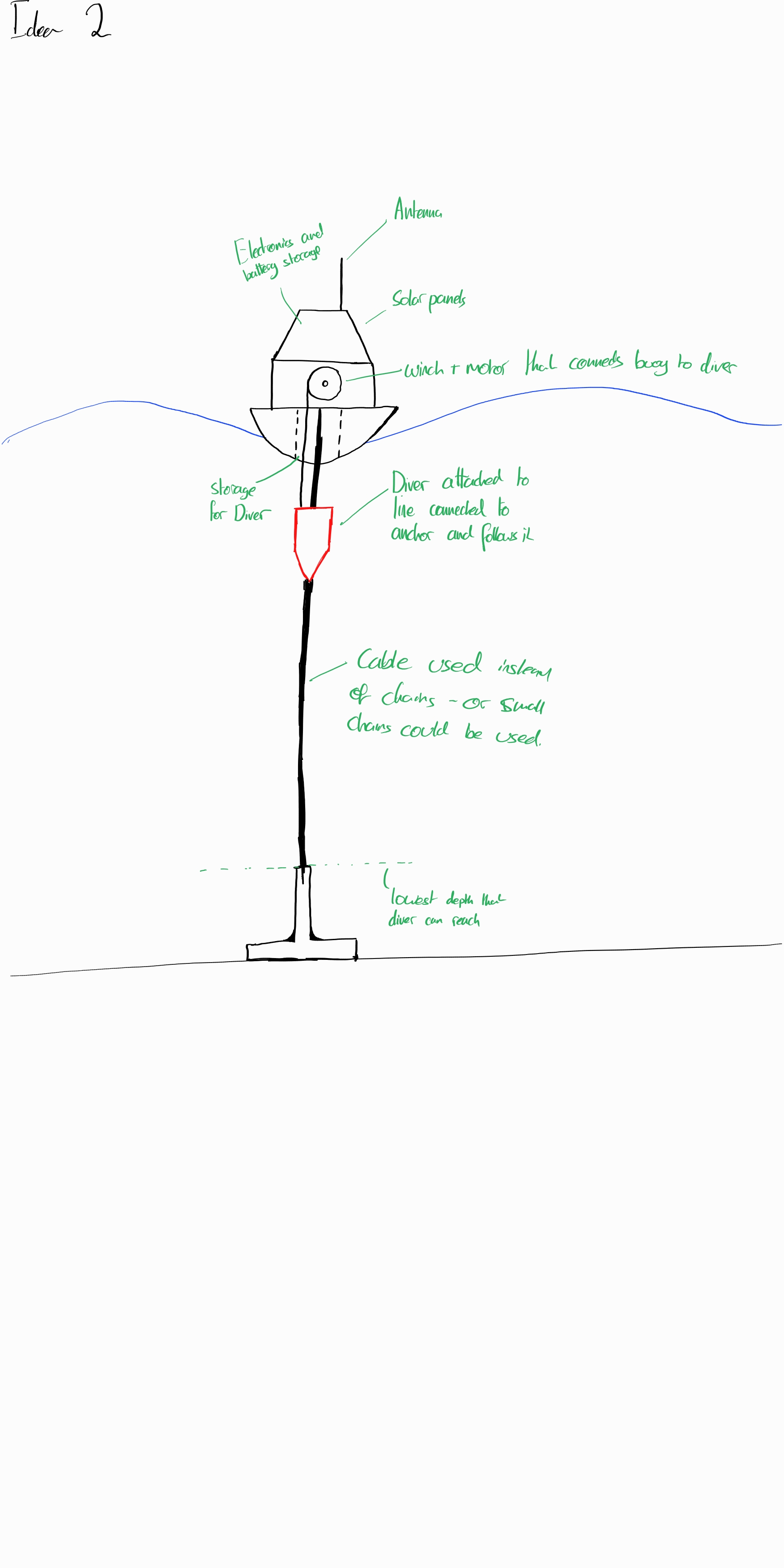
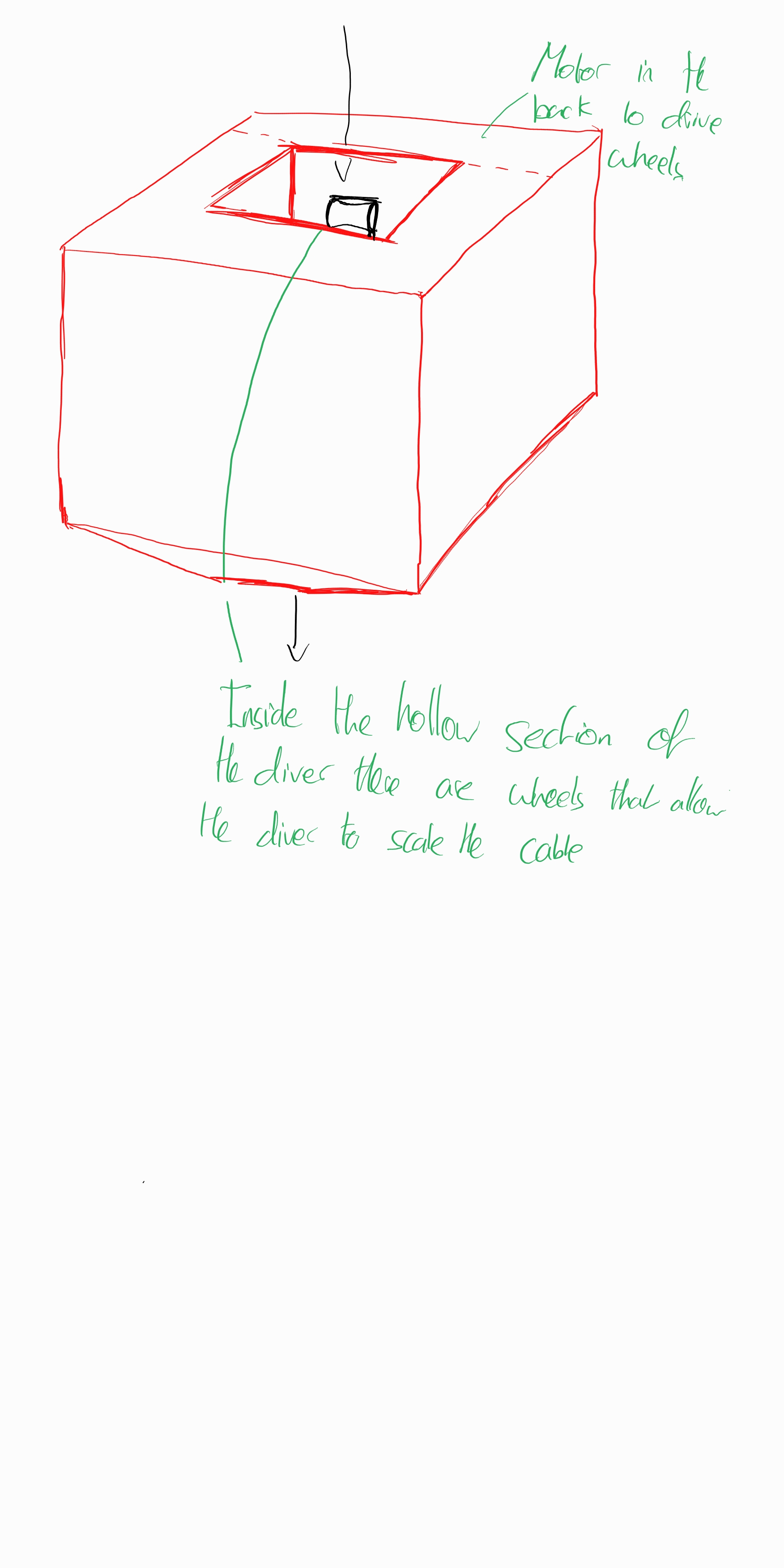
The second concept uses the idea that the diver is able to control its own depth by using a motor that is fixed inside of the diver. This would mean that there would be less stress on the wires (attached to the winch) that connect the diver to the buoy as the wires would not have to be able to withstand the weight of the diver by itself. The chains connecting the the anchor are replaced with a cable/ line such that the wheels used to move the diver would always stay in contact with the cable at all times. Furthermore the cable would go through a hollowed out gap, as seen in the second image below, to prevent an asymmetrical distribution of weight as much as possible to prevent the diver from detaching from the the cable and being swept away.
Flaws:
- Uses an Anchor, in many Coral Reefs, anchors are banned because they would destroy large amounts of coral that would take many years to regrow.
- Motor inside of the takes up extra space which could have been used for different sensors.
Developed Designs
Developed Idea 1
Concept:
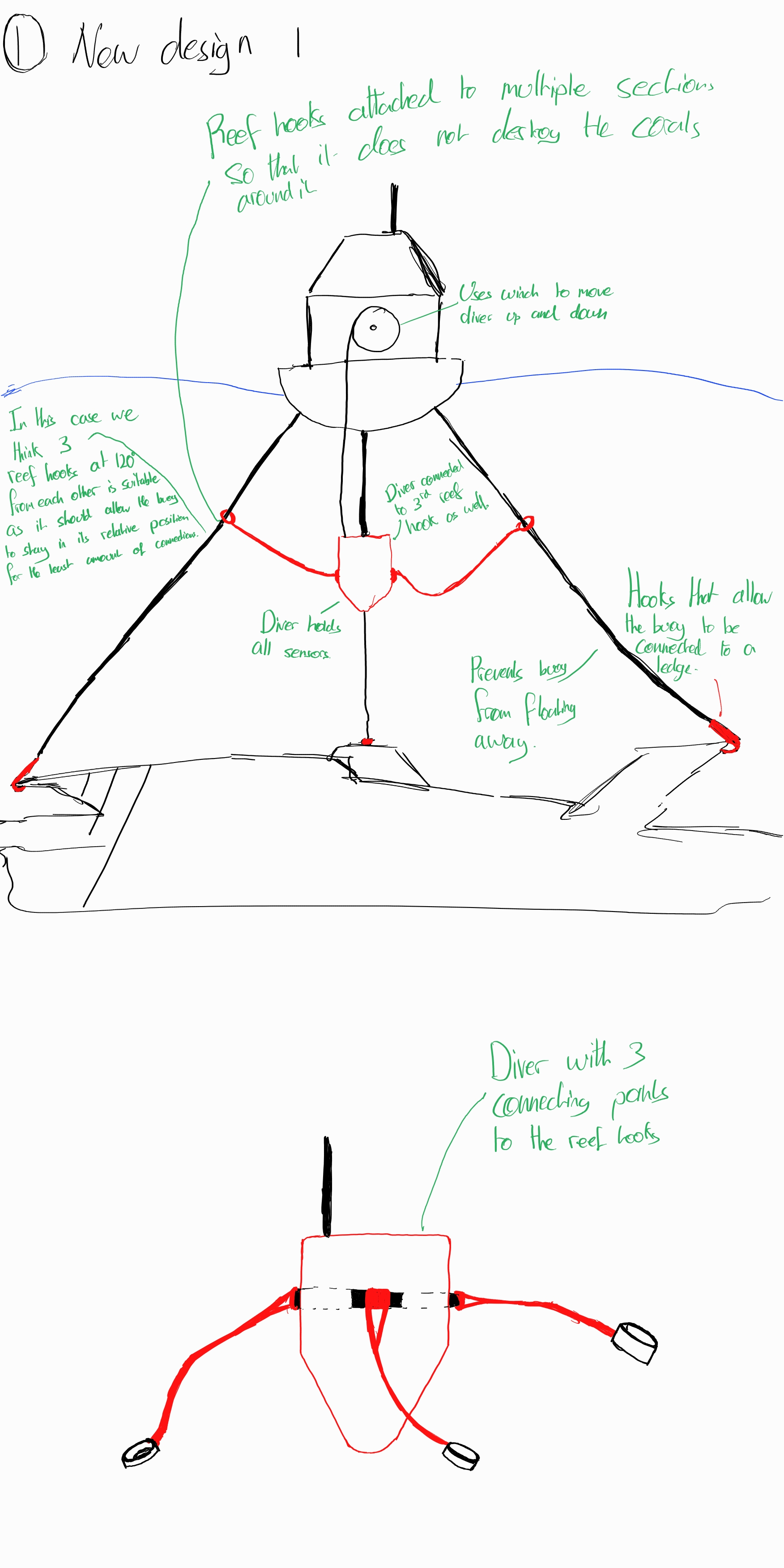
This Developed Design uses Reef hooks as compared to the initial anchor. Therefore it would be attached to ledges rather than being deployed down which would minimise the damage done to surrounding corals. The Design would use three separate reef hooks attached in a wide area at approximately 120 degrees from one another such that the buoy would stay in an approximately central location with reference to the locations where the reef hooks are attached. Furthermore the diver would be connected to all 3 lines to act as guides so that the diver is unable to be swept away as it is lowered into the water.
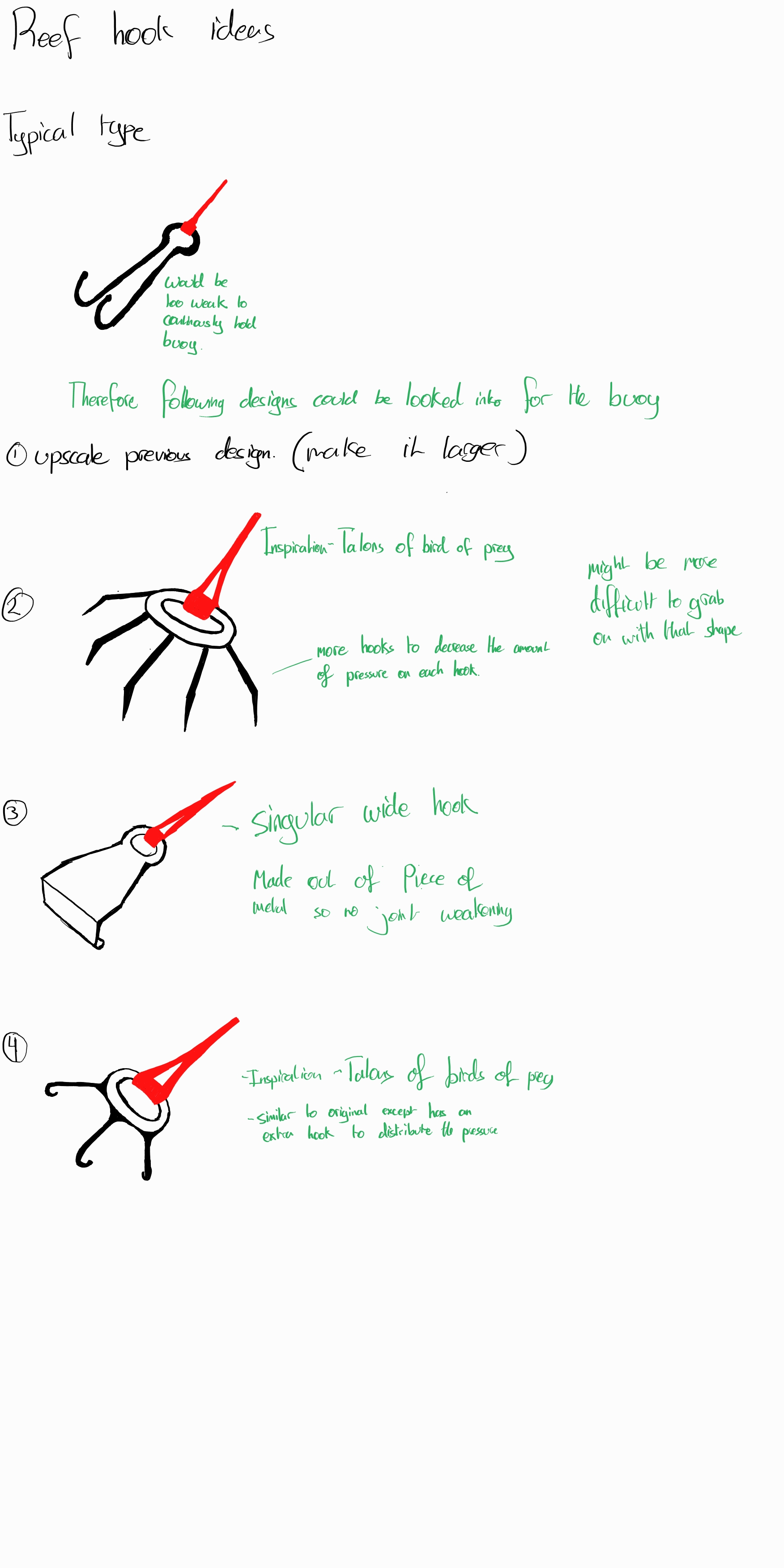
The second image shows potential ideas for reef hook designs that could be used be used. This was investigated as conventional Reef Hooks were design for divers to hook on briefly so that they would not get swept away. As such the design had to be adjusted to be able to last longer underwater holding the buoy in place.
Flaws:
- Reef hooks are located further away from one another. Therefore a lot of space would be taken up underwater by the buoy, this might make it more difficult for larger marine animals to swim in the general location of the buoy without potentially dislodging one of the reef hooks by accidentally crashing into one of the lines.
- The 3 extra cables that connect the diver to the lines (preventing diver from being swept away) would have to be very long for the area near the bottom. This would mean that the diver would either have to be able to retract the cables into it, taking up valuable space that could have been used for carrying sensors. Or the cables would have to be left to stay out all the time, which would bring about the problem that the cables would be left to float all the time unless the diver is at its maximum depth. This could mean that the cables could degrade quicker.
- The Reef Hooks would need to be setup manually by divers. This would bring about the problem of how getting suitable divers to get to the depths required along with the safety of the divers and the time it takes for the setup.
Developed Idea 2
Concept:
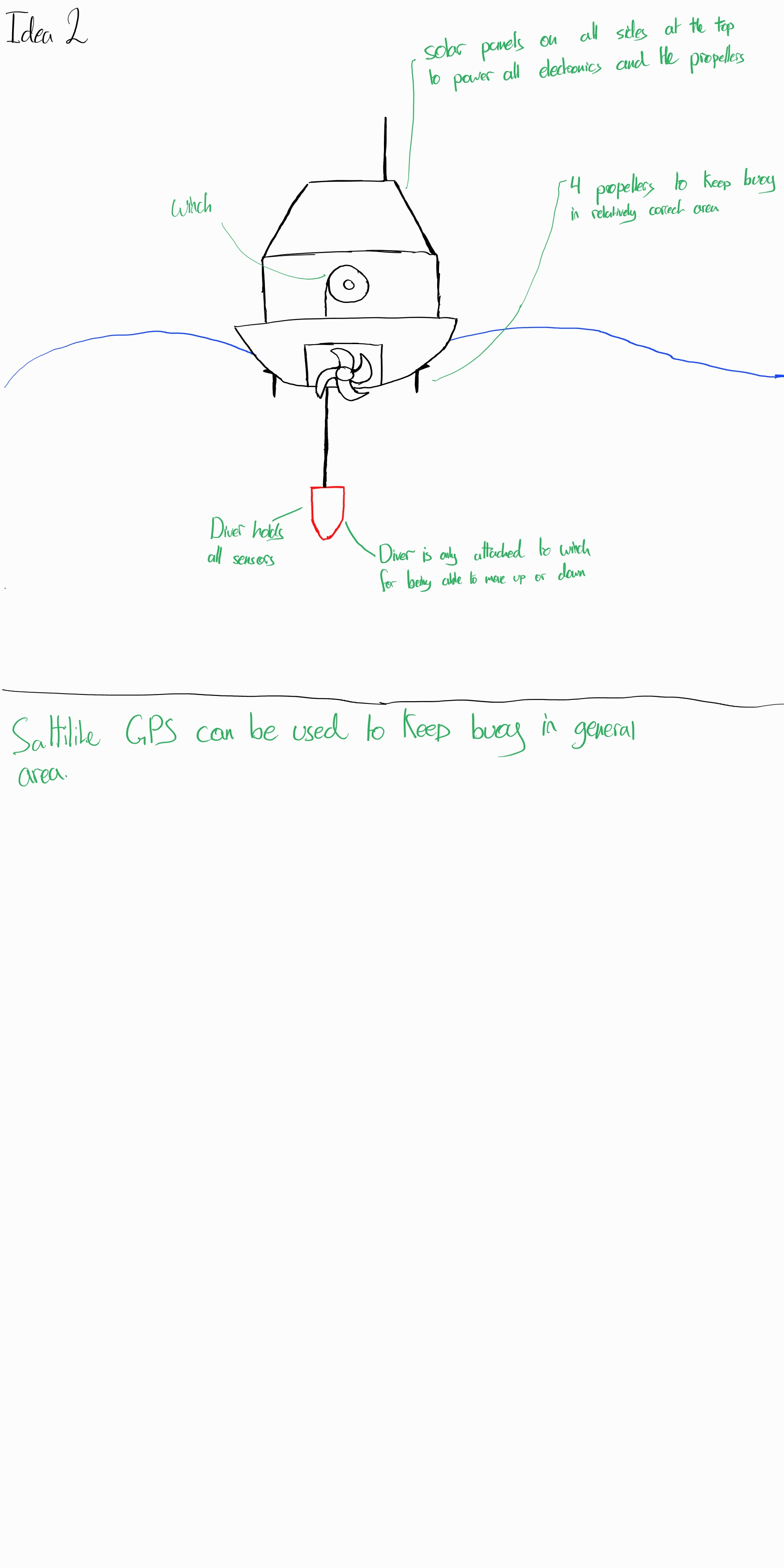
This concept removes the need for anchoring and instead has the buoy automatically move to the desired destination through the use of GPS from satellites. The reason it is thought to be feasible is because coral reefs act as natural wave barriers due to the fact that they are able to diminish the power of waves coming from the ocean by approximately 86 - 97%[26]. For this design the diver is not guided by any line connected to an anchor or reef hook. Instead it is will be left to sink due to its weight, but the winch will control the depth at which the diver is allowed to ago, along with pulling it back up towards the surface.
Flaws:
- Much higher power consumption. A buoy with this design would have to consume a lot more power as it would have to automatically self correct its position using propellers so that it can stay the correct relative location that the user would want to measure, without being slowly swept away. As such this might impact the overall performance of the sensing equipment and the buoy overall.
- In the case of tropical storms, there is a chance for the buoy to be tipped over/ upside down as it is not connected to anything underwater. Furthermore tropical storms or strong winds could be able to send the buoy off course due to the fact that it is not tethered to any heavy object under the water.
Developed Idea 3
Concept:
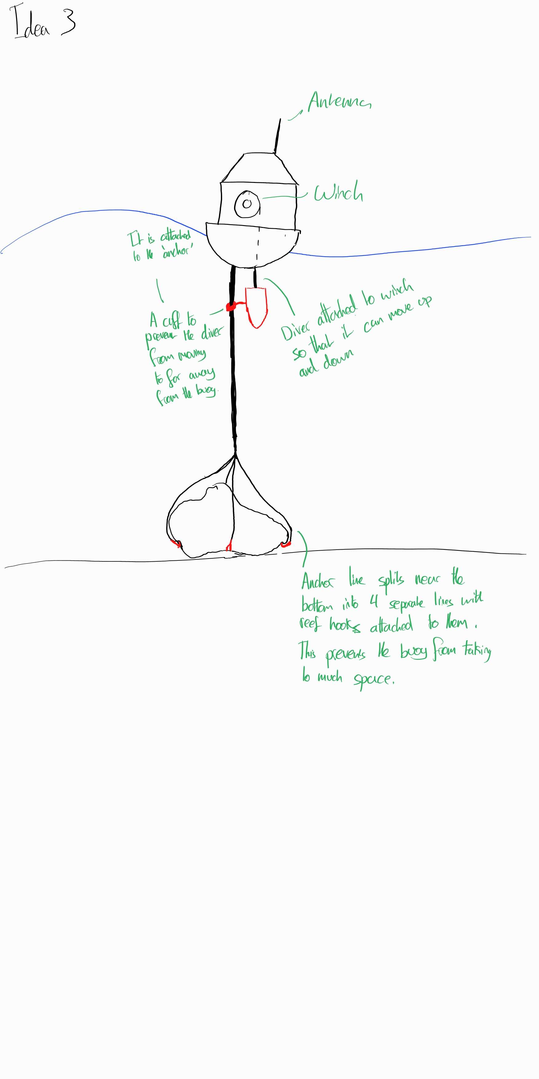
The concept for this design is a mix between using an anchor and reef hooks. It uses a large object, such as a boulder, underwater as a 'natural' anchor to which 4 reef hooks are attached to it. This way it does not introduce a very heavy load that could destroy the corals underneath it. Otherwise the idea has similar elements to the first initial design when it comes to the diver.
Flaws:
- Reef Hooks would have to be manually secured by divers, therefore it would be important to pay attention how deep the location is because certain depths require more experienced divers.
- The location where the buoy would have to be surveyed first to check if a 'large object such as a boulder is within the vicinity to act as the 'natural' anchor. If the boulder thought to have been acceptable is too light, then it could even act as an anchor, destroying the surroundings.
Final Design Choice
Concept:
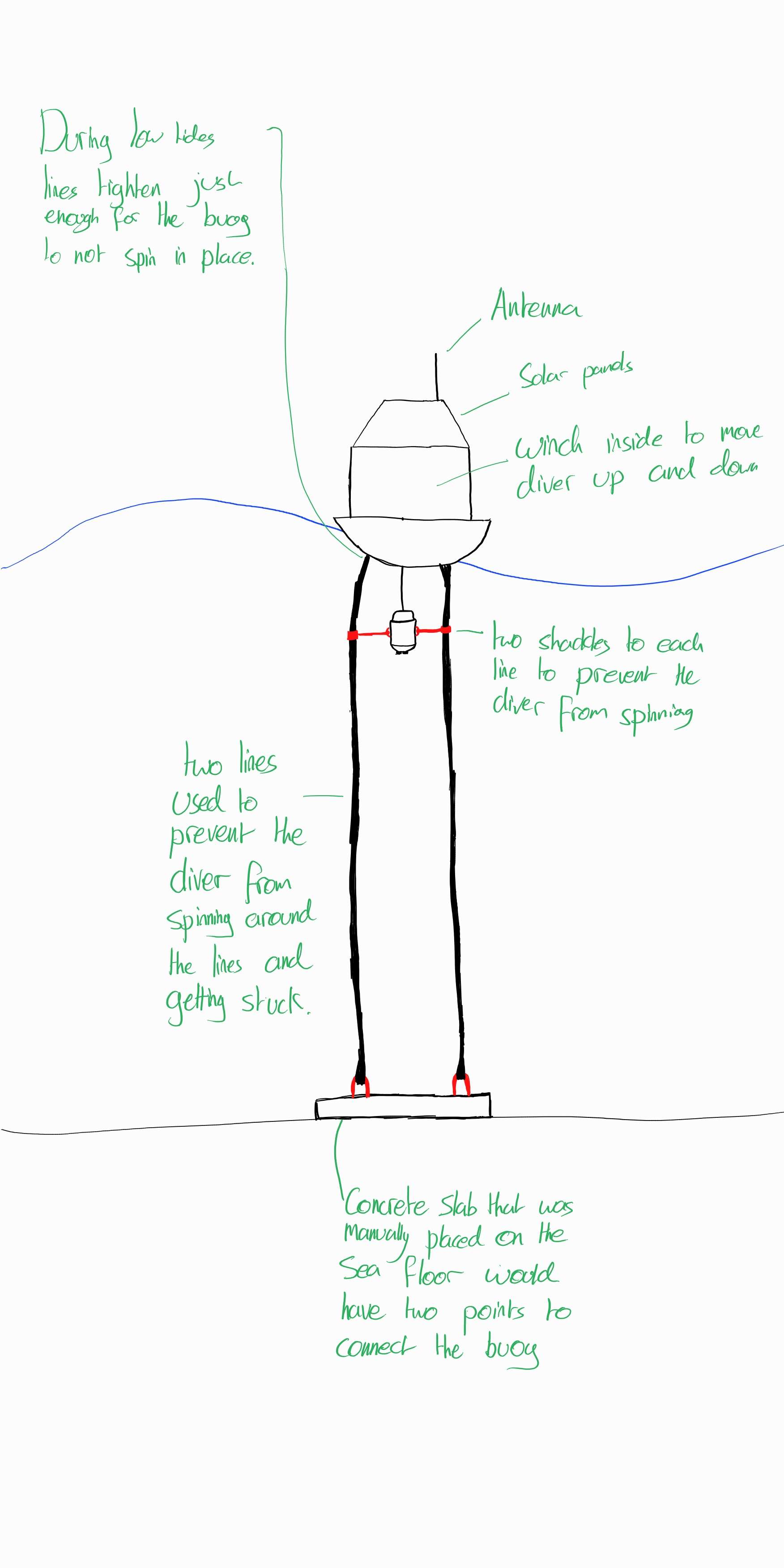
This design was made based on issues that were found from both the interviews and the models created. The main issue solved from the interviews was given by an interviewee who mentioned how although anchors are not allowed, usually a concrete slab would be an acceptable alternative. This stems from the fact that typical anchors would be dragged across the seafloor, but a concrete slab would be too heavy to be moved and as such would stay in place.
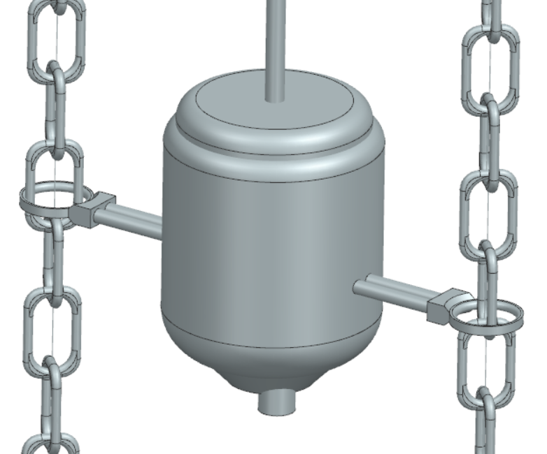
The second problem that was found from the simulations was how the diver could become tangled with the anchoring line by circling around it and interweaving the wire connecting the diver and the anchoring line. This was solved in this design by adding a second anchoring line and connecting the diver to both such that it is unable to rotate around one of the lines.
Furthermore, the shape of the diver was adjusted such that it had a larger volume so that more sensors can be placed inside of it. This was previously explored in the earlier sections prior to the designs
Flaws:
- Requires prior research on location for where the buoy will be placed.
- Would require experienced divers to safely place the concrete slab in the correct position, depending on the depth. Heavier concrete slabs would have to be lowered by a boat with divers guiding it. Whereas for lighter concrete slabs, a type of balloon is needed to slow down the descent of the slab.
Potential improvements
The following section will look into potential ideas that could be looked further into if the project was continued. The potential topics to look into were:
- The automisation of deploying the buoys. This would mean that the buoy would just need to be released in the approximate location where it was decided for the buoy to be. Following this the concrete slab or reef hooks could attach themselves to wherever it is required for them to be deployed. This would take out the requirement for experienced divers to be used to deploy the buoys and take out the long process of going to deeper depths and having to slowly move upwards to the surface over a span of multiple hours
- Dynamically adjusting anchor lines (connecting buoy to concrete slab or reef hooks) to keep the buoy from spinning in place in the case of the final design and tangling the two anchoring lines. This could be done by having the lines tighten or loosen depending on if it is a high or low tide. This way for the final design, the lines would not twist together and prevent the diver from moving downwards.
Research Relating to how the Real World Influences Buoys and its Surroundings
Forces present on a buoy
To be able to make a reasonably realistic simulation of our buoy, it is important to know what all the forces, and their average values, on a bouy located in the Great Barrier Reef would be.
Wind speeds and oceanic currents
To begin, their is wind present on the water surface. Wind is one of the most important factors when it comes to the base of the bouy, as wind is one of the main drivers when it comes to ocean currents, and are therefore correlated[27]. Below, a graph of the average windspeeds and subwater currents is shown for the entire coastline of the Australian province Queenslands containing the Great Barrier Reef. From these graphs, we can see that the speeds of the current acting on the buoy can change depending on the specific location that a researcher would choose. Therefore, our simulation should take into account all of the edge cases, and be run on the maximum average current speeds.
-
Average yearly windspeeds and subsurface oceanic currents[28]
Buoyance force and gravity
As with all objects floating on a water surface, our buoy will have some form of buoyance force. This buoyancy force, Fb,has been previously derived when talking about the diver of our buoy, however, it also effects the base of our bouy. For the base, we have not specifically calculated all the values as we have doen for the diver. This is because the main focus of this project is the diver and how it is able to move up and down. To make sure our simulation would then be realistic, we have assumed that when implementing our design in the real world, a sufficient amount of bouyancy material will be used. This would make sure that the buoyancy force would be able to overcome any value of the gravitational force, dependent on how many, and what kind of sensors a researcher would desire.
Mechanics of the Diver Movement
In this section it is describe in detail how the diver will actually be able to move up and down through the water. Furthermore, the limitations that the diver will have due to the chosen design are discussed.
In earlier sections it is described how the diver will be able to sink, due to its high mass volume ratio which is significantly higher than the density of the water. Due to this, the gravitational force which works on the buoy is substantially higher than the buoyant force. In order to compensate this overshoot of gravitational force to control the diver to make sure it does not immediately sink to bottom, a winch is added which is attached to the diver with a cable. The base of the buoy will then make sure the net force on the buoy is zero due to its low mass volume ratio and thus high buoyant force. The diver will then remains in its place due to Newtons second law of motion.
A specification for the diver of the buoy is that it should be able to maneuver in a straight line underneath the base of the buoy. Multiple solutions were developed before the choice was made of having 2 anchor chains. Having these 2 chains allows the diver to be linked to the chains which would then guide the diver down. This concept is tested in our Unity simulation which would proof this concept.
A result of these two chains is that it increases the cost and installation complexity of the buoy.
Simulations & Demo
Buoy model
In order to simulate the buoy first a model is needed. So one was made using NX siemens. This model was manly based on our own design concepts as well as state of the art research and resulted in the image below. First is the entire model of the buoy, then the final design for our diver attached to two chains as we found out one chain posed a problem with the buoy turning. Lastly there's a picture of the winch and gear system, in this picture two gears can be seen. To the rightmost gear an electro motor would attached to power the winch and allow the diver to go up and down. The dimensions of the winch might need to be readjusted depending on the length of cable needed for the diver. The current dimensions suffice for our design goal.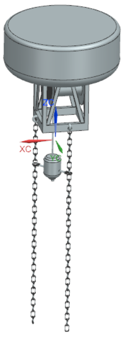
Unity Demo (physics simulation)
Repository Link: https://gitlab.tue.nl/use-robotseverywhere-group7/unity-demo-for-0lauk0-2022-3-g7.git
Goal
This is not meant to be the final product, rather main goal of using unity is to visualize our design concept, and additionally to get some insight into how to improve the design further.
Implementation
The features and the components that have been realized in the unity are listed below:
- Wave of the ocean
- return wave height given x and z coordinate
- The chains
- collision with the diver
- connect the buoy and the anchor
- The diver
- Its 3D model
- the mechanic of being dragged down with gravity
- the mechanic of being pulled down by the force of the shaft on the buoy
- The buoy
- Its 3D model
- buoy’s buoyancy, meaning the buoy floats up and down depending on wave height.
Insight on design
Despite the main objective of this unity demo being mainly for visualization of our purposed design concept, some insights were gained in the process, such as the fact that we did not take into account the occurrence of the diver spinning on the chain’s axis. Thus we have changed our design accordingly to mitigate such occurrences (make it so that we have two chains that connect the buoy and the anchor).
Conclusion
In our research we focused on a better and autonomous way to collect data in coral reefs. We focused on the Great Barrier reef to use as reference for our design. Many design choice needed to be made from how we would keep the buoy at one place, to how the diver would change it depth. Based on literary research and interviewing coral reef researchers, we decided on these design choices. In our design process the challenge we faced was the propagation of the diver going straight down with respect to the buoy. By performing simulations in Unity we solved this by testing new ideas we thought of. In the process of our design we came across potential alternative solutions or possible improvement which could be done in the future. In conclusion, we design a buoy which can be used by researchers as an autonomous data collection system for which they can specify the specific data they want to be measured and we though of possible improvement for future researchers.
Reference list
- ↑ 1.0 1.1 . M. (2023, 11 januari). Oceans - United Nations Sustainable Development. United Nations Sustainable Development. https://www.un.org/sustainabledevelopment/oceans/
- ↑ Hoegh-Guldberg, O., Mumby, P. J., Hooten, A. J., Steneck, R. S., Greenfield, P., Gomez, E., Harvell, C. D., Sale, P. F., Edwards, A. M., Caldeira, K., Knowlton, N., Eakin, C. M., Iglesias-Prieto, R., Muthiga, N. A., Bradbury, R., Dubi, A., & Hatziolos, M. E. (2007); Coral Reefs Under Rapid Climate Change and Ocean Acidification. Science; 318(5857); 1737–1742; https://doi.org/10.1126/science.1152509
- ↑ Chen, Y. (2022b, december 19). Press Release: Nations Adopt Four Goals, 23 Targets for 2030 In Landmark UN Biodiversity Agreement. United Nations Sustainable Development.
- ↑ https://thegreentimes.co.za/wp-content/uploads/2022/01/impact-of-ocean-noise-pollution-on-fish-and-invertebrates.pdf
- ↑ Great barrier reef foundation; Australian Government; https://www2.gbrmpa.gov.au/about-us/partners/great-barrier-reef-foundation#:~:text=The%20Reef%20Trust%20Partnership%20is,the%20Great%20Barrier%20Reef%20Foundation.
- ↑ Tourism on the Great Barrier Reef; Australian Government; https://www2.gbrmpa.gov.au/our-work/managing-activities-and-use/tourism/tourism-great-barrier-reef
- ↑ https://oceanservice.noaa.gov/facts/coralwaters.html
- ↑ https://oceanservice.noaa.gov/education/tutorial_corals/media/supp_coral09a.html
- ↑ 9.0 9.1 V.Bondur; Complex Satellite Monitoring of Coastal Water Areas; Scientific Center of Aerospace Monitoring “AEROCOSMOS”; 2005; https://citeseerx.ist.psu.edu/document?repid=rep1&type=pdf&doi=184fae2e4e23afcaf6b7f5807988a2f0411af399
- ↑ Kathleen Dohan, Nikolai Maximenkoh; MONITORING OCEAN CURRENTS WITH SATELLITE SENSORS; Oceanography; Vol.23; December 2010; pages 94-103; https://www.jstor.org/stable/24860865
- ↑ Steve Groom et al.; Satellite Ocean Colour: Current Status and Future Perspective; Front. Mar. Sci., 29 August 2019; Sec. Ocean Observation; vol. 6; https://www.frontiersin.org/articles/10.3389/fmars.2019.00485/full
- ↑ Shawna A. Foo, Gregory P. Asner; Scaling Up Coral Reef Restoration Using Remote Sensing Technology; Front. Mar. Sci., 13 March 2019; Sec. Marine Conservation and Sustainability; vol. 6; https://www.frontiersin.org/articles/10.3389/fmars.2019.00079/full#B23
- ↑ https://www.keylargoscubadiving.com/scuba-gear/how-much-does-scuba-gear-cost/
- ↑ John D. Hedly, et al.; Remote Sensing of Coral Reefs for Monitoring and Management: A Review; 6 February 2016; https://www.mdpi.com/2072-4292/8/2/118
- ↑ 15.0 15.1 Chris M. ROELFSEMA, Stuart R. PHINN, and Karen E. JOYCE; Evaluating Benthic Survey Techniques for Validating Maps of Coral Reefs Derived from Remotely Sensed Images; https://citeseerx.ist.psu.edu/document?repid=rep1&type=pdf&doi=d2fa3933919aa62688dce63b2cd06abaaabb4026
- ↑ hristine Ferrier-Pagès, Miguel C. Leal, Ricardo Calado, Dominik W. Schmid, Frédéric Bertucci, David Lecchini, Denis Allemand; Noise pollution on coral reefs? — A yet underestimated threat to coral reef communities; Marine Pollution Bulletin; Volume 165; 2021; https://www.sciencedirect.com/science/article/pii/S0025326X21001636
- ↑ lbaladejo, C.,; Soto, F.; Torres, R.; Sánchez, P.; López; J.A. A Low-Cost Sensor Buoy System for Monitoring Shallow Marine Environments. ; Sensors; 2012; https://doi.org/10.3390/s120709613
- ↑ 18.0 18.1 Young, Hugh. University Physics with Modern Physics, 15th edition. Page 401
- ↑ https://coralreeftkohli.weebly.com/great-barrier-reef.html
- ↑ Seawater Density Calculator; https://www.wkcgroup.com/tools-room/seawater-density-calculator/
- ↑ i::scan; http://www.i-scan.at/images/pdfs/iscan_ww_EN.pdf
- ↑ KAPTATM 3000 - AC4; https://www.neroxis.ch/wp-content/uploads/2020/04/DPM-18-082-002-E-KAPTA-3000-AC4_Brochure_EN.pdf
- ↑ Damon McMillan; Choosing Materials for Use in the Ocean; Blue Trail Engineering; Sep 9, 2019; https://www.bluetrailengineering.com/post/choosing-materials-for-use-in-the-ocean
- ↑ 24.0 24.1 ProtoLabs; Metal Fabrication: A Guide to Manufacturing Metal Parts; https://www.protolabs.com/resources/guides-and-trend-reports/metal-fabrication-a-guide-to-manufacturing-metal-parts/#HardMetals
- ↑ Stainless Steel Density; DONGSHANG STAINLESS STEEL; http://www.dsstainlesssteel.com/stainless-steel-density/
- ↑ Communications and Publishing; Coral Reefs are Critical for Risk Reduction & Adaptation; USGS, Science for a changing world; May 13, 2014; https://www.usgs.gov/news/national-news-release/coral-reefs-are-critical-risk-reduction-adaptation
- ↑ Australian Institute of Marine Science; AIMS eReefs Visualisation Portal; GBR4; https://ereefs.aims.gov.au/ereefs-aims/gbr4/temp-wind-salt-current#frame=Yearly;region=queensland-1
- ↑ Australian Institute of Marine Science; AIMS eReefs Visualisation Portal; GBR4; https://ereefs.aims.gov.au/ereefs-aims/gbr4/temp-wind-salt-current#frame=Yearly;region=queensland-1
![Average yearly windspeeds and subsurface oceanic currents[28]](/images/Average_yearly_stuff.png)