Number, speed, size and energy consumption of the robot
The energy consumption of our robots is closely linked to how many robots we use, how fast they are and how large they are. In order to see what kind of robots would be viable a detailed analysis has been made to determine how exactly the needed solar power depends on these variables. Or course energy consumption is not the only design consideration that affects this, since a gigantic robot would have problems navigating the terrain and a miniscule robot would get crushed of someone happens to step on it. However, energy consumption is a neccesary and leading variable to consider since if the robot needs too many solar panels it will no longer be viable to use.
A basic energy model
The robot’s task is to move [math]\displaystyle{ s_{well} }[/math] meters to the well, and then take [math]\displaystyle{ m_{water} }[/math] kg back over the same distance to the village. In terms of energy the main costs will be from rolling friction and, depending on the speed, air friction. In addition, there will also be an energy cost for operating the boardcomputer and other electronics, but these are fairly small compared to the energy needed to move the robot so we will ignore this to keep the calculations a bit easier.
Another factor that will be ignored is height. The energy cost of climbing a hill [math]\displaystyle{ g*h*m_{total} }[/math] is recouped as we go down the hill on the other side. This of course only holds if the robot is actually able to reach the top of the hill, but that is outside the scope of these energy production calculations. The other height difference we need to consider is that between the village and a pump since the weight of the robot changes at those points. It's a benefit if the pump is higher and a loss of the village is higher. However, this factors is effectively impossible to consider in these calculations since it needs a detailed knowledge of which exact hills we will encounter at what point in the route. This will differ wildly between locations. It should also be noted that the impact of this on actual running costs is fairly small. If we assume a 10 meter height difference(village being higher), and we need to carry 5000 liters of water per day as is the scenario, we need an extra [math]\displaystyle{ 5000*10*9.8/3600000=0.14 }[/math] kwh of energy per day for the total energy used by all robots. As we will see, this is a fairly insignificant amount of energy compared to the total, so we will ignore it to simplify calculations
We will also be ignoring the energy needed to accelerate the robot/change the speed of the robot. The amount of energy this requires is [math]\displaystyle{ E_k=\frac{1}{2}m*v^2 }[/math]. If we were to assume the robot weighs 10000 kg and needs to move at a speed of 7 m/s(further on in this document we will see that this is already faster than what is actually needed for our requirements), we need [math]\displaystyle{ E_k=\frac{5000*7^2}{2*3600000}=0.03 kwh }[/math]. Compared to the energy costs we will find this does not make a large impact on the total amount of energy, so we will ignore this to simplify the calculations.
The rolling friction force is(assuming the worst case scenario of a level surface)
[math]\displaystyle{ F_{roll} = c_{rr} * F_n = c_{rr} * m_{total} * g }[/math]
Note that while [math]\displaystyle{ c_{rr} }[/math] and [math]\displaystyle{ g }[/math] are constant, [math]\displaystyle{ m_{total} }[/math] is not since the water tank will be empty on the way towards the well and filled on the way back.
So the energy lost to rolling friction in a single trip will be
[math]\displaystyle{ E_{roll} = f * s
= f_{roll,empty} * s_{well} + f_{roll,full} * s_{well}
= c_{rr} * g * s_{well} * (2 * m_{robot} + m_{water}) }[/math]
If we assume that the watertank will maintain the same shape regardless of its content the air friction will be constant throughout the ride(assuming constant speed). We then get [math]\displaystyle{ f_{air} = \frac{1}{2} * CdA* p * v^2 }[/math], where [math]\displaystyle{ p }[/math] is air density and [math]\displaystyle{ CdA }[/math] is the air drag coefficient times the frontal surface area. Multiplying(integrating) with the distance we need to travel in a trip, we get [math]\displaystyle{ E_{air} = \frac{1}{2} * s_{well} * CdA * p * v^2 }[/math] Note that that while it is possible to use different speeds for different parts of of trip, that would not be energy efficient since the speed is squared in this equation.
This then places the total energy used in a trip to and from the well at [math]\displaystyle{ E_{needed} = s_{well} * (c_{rr} * g * (2m_{robot} + m_{water}) + \frac{1}{2} * CdA * p * v^2 }[/math] This is of course only the energy output that's needed to keep the robot moving, and does not yet take into account the efficiency of the motor. This then gives [math]\displaystyle{ E_{used} = \frac{s_{well} * (c_{rr} * g * (2m_{robot} + m_{water}) + \frac{1}{2} * CdA * p * v^2}{e_{motor}} }[/math]
Estimating the variables
In order to actually use this formula we will need to find values for the variables. Some of them are constants(either physical or from the scenario) and will be fairly easy to fill in, but parameters that relate to the mass and speed of the robot
For the gravitational acceleration [math]\displaystyle{ g }[/math] we can take the usual value of [math]\displaystyle{ g=9.8 }[/math]
From the scenario we already know that [math]\displaystyle{ s_{well}=3000 }[/math] meters and [math]\displaystyle{ m_{water}=5000 }[/math] kg(assuming a denstity of 1 kg/l for the water).
The rolling coefficient [math]\displaystyle{ c_{rr} }[/math] is primarily determined by the tires used and by the terrain we're moving over. For the scenario we will be moving across solidground. This can be best modeled as solid sand in our scenario, which gives a rolling coefficient of </math>0.06</math>. Note that this is significantly higher than moving over more agreeable surfaces such as tarmac, where the rolling coeficient is usually a factor 10 or more lower. [1]
The drag coefficient of a pickup truck is about 0.47[2]. For the frontal area we assume we have a a box using a square water tank. Then the frontal area is [math]\displaystyle{ (m_{water}/1000)^{2/3} }[/math]. This then gives [math]\displaystyle{ cda=0.47(m_{water}/1000)^{2/3} }[/math].
Relation between water per trip, speed and number of robots
We need to make at least [math]\displaystyle{ n_{trips,needed} = \frac{m_{required}}{m_{water}} }[/math] trips to the well per day to ensure that enough water is transported to the village.
To see how fast a robot needs to be to make this target, we need to consider that the robot will not be moving 24/7. It will need to spend time filling and unloading, during which it is not moving, and it might also be possible the residents don’t want to have the robot moving during the night. Here we also need to start considering the possibility of using multiple smaller/slower robots instead of a single large/fast robot. We let [math]\displaystyle{ p_{idle} }[/math] be the fraction of time a robot spends doing things that are not moving. Using [math]\displaystyle{ s=v*t }[/math], we then get [math]\displaystyle{ n_{trips,achieved}=\frac{n_{robots}s_{driven}}{2s_{well}}=\frac{n_{robots}v_{average}*24*3600*(1-p_{idle})}{2s_{well}} }[/math] The factor 2 for [math]\displaystyle{ s_{well} }[/math] is there because [math]\displaystyle{ s_{well} }[/math] is only the distance to the well, which is half the distance we need to travel. So the number of achieved trips needs to be at least the number of required trips, we get [math]\displaystyle{ \frac{n_{robots}v_{average}*24*3600*(1-p_{idle})}{2s_{well}}\geq m_{required}/m_{water} }[/math] So we need to ensure that the speed we pick satisfies this inequality if we want to be able to reach the necessary amount of water each day.
For [math]\displaystyle{ {p_{idle}} }[/math] we take 20% as an upper limit for the time the robot is either loading or unloading its water tank. This is fairly high so it should ensure that are on the safe side. However, we also need to consider the robot cannot function during the night for a variety of reasons, such as people wanting some quiet during the night, so we will only be able to operate for 16 hours a day. Adding the loading times to this gives us 12.8 hours of movement, giving a [math]\displaystyle{ p_{idle}=0.45 }[/math].
If we seek to minimize energy needs, we will want to minimize speed as much as we can, so we will be taking the inequality we found earlier and use as an equality. Rewriting it to get the needed [math]\displaystyle{ m_{water} }[/math] for a certain speed and idle time we get
[math]\displaystyle{ m_{water}= \frac{m_{required}*s_{well}}{n_{robots}v_{average}*24*3600*(1-p_{idle})} }[/math]
Using various possible combinations of possible speeds and idle times, we get table 1. Note that not all speeds and volumes are necessarily achievable.
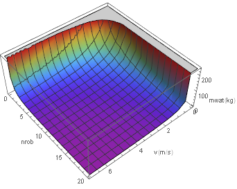
If we graph this with multiple robots, we get the following graph(note that the origin is in a nonstandard position to better show the graph):
Note that behaviour is determined by the divisions by both [math]\displaystyle{ v }[/math] and [math]\displaystyle{ n_{robots} }[/math]. This means that while it may be worthwhile to increase the number of robots or speed to keep away from the asymptotes we're seeing in this graph, but there aren't any real benefits to really large values if we consider the size of the water tank.
Estimating the mass of the robot
The hardest variable to estimate is the mass of the robot. This mass is the sum of each individual mass of various parts of the robot, but the mass of some parts of the robot is determined by the total mass of the robot. This results in a very hard to solve system of equations. The mass of the robot is determined by:
- Frame
- Wheels
- Motor
- Battery
- (unloaded) water tank
- Electronics
Note that the solar panels are ignored because we will find that the mass of the battery is too large to put on the robot in its entirety. This will result in having a charging station seperate from the robots. Moving (part of) the batteries off the robot will also result in the solar panels being moved off the robot as well, so they are then no longer relevant to determine the mass of the robot.
Electronics are going to give a fairly marginal addition to the mass of the robot in comparison to other factors, so we will ignore it. The weight of the water tank will be purely dependent on the volume of water we want to carry. Using the tanks available at tanks direct we get the following weights:
- A 5000l tank weighs about 120 kg, giving [math]\displaystyle{ 0.024 }[/math] kg/l
- A 1250l tank weighs about 35 kg, giving [math]\displaystyle{ 0.028 }[/math] kg/l
- A 227 l tank weighs about 6 kh, giving [math]\displaystyle{ 0.026 }[/math] kg/l
- A 100l tank weighs about 2.5 kg, giving [math]\displaystyle{ 0.025 }[/math] kg/l
So it seems the weight of the water tank is about linear in the weight we need to carry for about 0.025 kg/l.
The rest of the masses will be a lot harder to get a good estimate of since they are all interdependent:
- The mass of the wheels will depend on how much weight they need to carry.
- The mass of the motor will also depend on how much mass they need to move.
- Similarly, the mass of the batteries will depend on how much energy is needed in 1 trip, which will depend on the total mass as well.
- The mass of the frame will mostly depend on how much volume it needs to encase.
This results in a lot of masses that are interdependent on each other. The general approach is to try and derive a series of formulas for each of these masses in terms of the other masses, speed and the already known constants. Then we will try if Wolfram Mathematica is capable of finding a solution for these formulas in terms of speed(which should be possible since this will give 4 equations and 5 unknowns, with one of them being speed).
Battery mass
First the mass of the batteries. This will need to be enough for the robot to last [math]\displaystyle{ {d_{endep}} }[/math] days without a power source, with an extra security buffer in case conditions get a bit worse and to take the ignored factors in energy calculations into account.
We will have some energy-density [math]\displaystyle{ \rho_{energy}\ j/m^3 }[/math] for the battery.
We know we will need [math]\displaystyle{ E_{used}*b_{sec} }[/math] to move the robot for a single roundtrip to and from the well, where [math]\displaystyle{ e_m }[/math] is the efficiency of the motor(roughly [math]\displaystyle{ 0.80 }[/math] [3]) and [math]\displaystyle{ b_{sec} }[/math] is the security buffer which we will take as [math]\displaystyle{ 1.15 }[/math].
We need to do [math]\displaystyle{ n_{trips,achieved} }[/math] trips to the well per day, and do it for [math]\displaystyle{ d_{endep} }[/math] days. So then the total energy we need to store in the battery is [math]\displaystyle{ d_{endep}*n_{trips,achieved}*E_{used}*b_{sec} }[/math]
We then get [math]\displaystyle{ m_{battery}
=\frac{d_{endep}*n_{trips,achieved}*E_{used}*b_{sec}}{\rho_{energy}} }[/math]
[math]\displaystyle{ =\frac{[s_{well} * (c_{rr} * g * (2m_{robot} + m_{water}) + \frac{1}{2} * CdA * p * (v_{empty}^2 + v_{full}^2))]*e_{motor}*d_{endep}*n_{trips,achieved}*b_{sec}}{\rho_{energy}} }[/math]
[math]\displaystyle{ =\frac{[s_{well} * (c_{rr} * g * (2(m_{motor}+m_{frame}+m_{battery}+m_{wheel}+m_{tank}) + m_{water}) + \frac{1}{2} * CdA * p * (v_{empty}^2 + v_{full}^2))]*e_{motor}*d_{endep}*n_{trips,achieved}*b_{sec}}{\rho_{energy}} }[/math]
Note that, other than the four masses, everything is either a constant of dependant on [math]\displaystyle{ v }[/math]. For energy density we can take li-ion batteries to get [math]\displaystyle{ 612000 }[/math] j/kg [4]
Motor mass
Then the motor: in order to keep a robot of mass [math]\displaystyle{ m_{total} }[/math] moving at speed [math]\displaystyle{ v }[/math], the motor must have a power of [math]\displaystyle{ p(m_{total})=v*(f_{roll}(m_{total})+f_{air}(m_{total}))=v*(c_{rr} * m_{total} * g+\frac{1}{2} * CdA* p * v^2) }[/math]. Note that in this case we are only interested in keeping the robot moving at all times, rather than energy. This worst case scenario will happen with the tank filled, which is why we are using [math]\displaystyle{ m_{total}=m_{robot}+m_{water}=m_{motor}+m_{frame}+m_{battery}+m_{wheel}+m_{tank}+m_{water} }[/math] here. However, we also need to take into account that the robot needs to be able to move up a hill. For a 5% hill we would need [math]\displaystyle{ m_{total}*g*v*perc }[/math] extra power, where [math]\displaystyle{ v }[/math] is the horizontal speed and [math]\displaystyle{ perc=0.05 }[/math] is the percentage of the hill. This then gives [math]\displaystyle{ p_{motor}=v*(c_{rr} * m_{total} * g+\frac{1}{2} * CdA* p * v^2)+m_{total}*g*v*perc }[/math]
Then we will need to get some estimate for the mass of the motor if we need some certain power output. For this we look at the power to weight ratio of [5], which gives a power to weigth ratio of a bit less than 110. We also looked at [6] giving a power to weight ratio of a bit more than 60 w/kg. So we can expect that a power to weight ratio of 80 is achievable. We will likely be able to do better, and if the motors turn out to be more powerful we get better ratios as well. Since the motor will be a relatively small part of the mass and we only need a bound that ensures we can get the power we need with our mass we will be a bit on the conservative side here and pick this value of 80 w/kg as our power to weight ratio.
This then gives in a mass formula for the motors: [math]\displaystyle{ m_{motor}=\frac{p_{motor}}{80} }[/math]
Wheel mass
Continuing with the wheels. For this we need to consider the needed groundclearance. This will be about 5 inches above the ground as we will argue later. This means that the wheels will need to have a minimum size no matter how large the robot is. We can use the wheels given by [7] giving us 4kg of mass in the wheels. These wheels have a load limit of around 540 kg. We will see in a moment that this will be more than enough for every size of robot we could seriously consider. Note that this means that the mass of the wheels is not dependent on the mass of the robot in our model. This is because by the time these wheels no longer apply the mass of the robot is alread fairly large. Ignoring what kind of wheels we would need for larger robots makes the model less powerful and less predictive for larger robots, but does make the model a lot simpler to handle.
It should also be noted that the mass of the wheels is only a fairly small contribution to the vehicle for heavier vehicles. One example of such is the Toyota Tacoma, where the ratio of wheel mass to total car mass is about 0.02 depending on the exact model used[8][9].
Frame mass
This leaves only the frame. We will model it as a simple square box with set thickness. The robot will likely not be box shaped, but this should give us a rough idea of much material we will need for our robot. If we have a given mass of water we need to be able to transport, we would need at least [math]\displaystyle{ (m_{water}/1000)^{\frac{2}{3}}*6m^2 }[/math] just to encase a square water tank. Note that this assumes we can't compress the water in the tank to achieve a better density than [math]\displaystyle{ 1 kg/l }[/math]. Since we need to be able to carry more than just the water tank, we will increase the length of the vehicle by a factor 2 as an absolute worst case estimate, giving us [math]\displaystyle{ (m_{water}/1000)^{\frac{2}{3}}*10m^2 }[/math] of surface area. For the thickness of the hull we will for now use [math]\displaystyle{ 1 cm }[/math]. For comaprison, the Mark V tank from ww1 had a thickness of 16 mm, so our 1 cm should be enough of an upper limit to deal with anything it can encounter. We then have a material volume of $surface*thickness$. If we then multiply by the density we get the mass of the frame. Using the alluminium alloy we are currently considering to use, we have a density of [math]\displaystyle{ 2700kg/m^3 }[/math].
Resulting mass
So now we have 4 equations for the masses we're missing, all dependent on each other. These equations are, using [math]\displaystyle{ m_{total}=m_{frame}+m_{motor}+m{wheels}+m_{battery}+m_{tank}+m_{water} }[/math]:
- [math]\displaystyle{ m_{frame}=density*thickness*(m_{water}/1000)^{2/3}*10 }[/math]
- [math]\displaystyle{ m_{motor}=\frac{v*(c_{rr} * m_{total} * g+\frac{1}{2} * CdA* p * v^2)+m_{total}*g*v*0.05)}{80} }[/math]
- [math]\displaystyle{ m_{wheels}=4 }[/math]
- [math]\displaystyle{ m_{battery}=\frac{[s_{well} * (c_{rr} * g * (2(m_{motor}+m_{frame}+m_{battery}+m_{wheel}+m_{tank}) + m_{water}) + \frac{1}{2} * CdA * p * (v_{empty}^2 + v_{full}^2))]*e_{motor}*d_{endep}*n_{trips,achieved}*b_{sec}}{\rho_{energy}} }[/math]
And additionally also [math]\displaystyle{ m_{tank}=0.025 m_{water} }[/math]
It should be fairly obvious that it is not viable to solve this system by hand. However Wolfram Mathematica is still capable of solving this system for the 4 masses. We then get multiple solutions for this system. All except one of these solutions require complex numbers, so we can safely dismiss those as a result of the complexity of the system rather than being real world solutions. There is only one real valued solution to the system:
[math]\displaystyle{ \frac{(-80.2574 - 341.103 v - 20.3404 n_{rob} v + n_{rob}^{1/3} v^{ 1/3} (-653.393 - 2.84217*10^{-14} v - 0.173981 v^3))}{(n_{rob} v (-5.08511 + 1. v))} }[/math]
This formula gives the following graph:
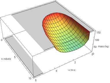
This was graphed with [math]\displaystyle{ d_{indep}=3 }[/math]. Using other values for [math]\displaystyle{ d_{indep} }[/math] does not give a qualitatively different graph.
Most striking is that the mass of the robot gets really high as we get to speeds even as low as 4 m/s. This is because a larger robot takes more energy. But to remain operational for 3 consecutive days we will need to have larger battery, which in turn leads to more energy consumption because the robot is now even larger.
If we were to remove the factor [math]\displaystyle{ d_{indep}*n_{trips} }[/math] from the battery mass(so remove the battery from the robot except for what we need for a single trip), we get the following graph and formula instead:
[math]\displaystyle{ \frac{(-1085.56 - 631.313 v + n_{rob}(-237.477 - 8.88178*10^{-16} v) v +
n_{rob}^{1/3} v^{
1/3} (-12233.5 - 0.0812779 v^2 - 0.188417 v^3))}{(n_{rob} v (-58.8986 +
1. v))} }[/math]
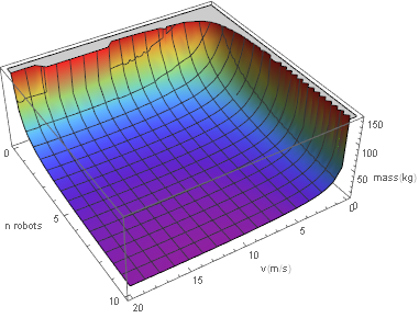
In this graph we more reasonable behaviour since the size of the battery is no longer exploding. The increase near [math]\displaystyle{ v=0 }[/math] and [math]\displaystyle{ n_{robots}=0 }[/math] is caused by the division we see in the formula. The formula does still eventually deal with battery size getting large, but this happens at much larger speedsthan we get if we were to put the battery on the robot itself. Note that this also means that our ignoring of the mass of the solar panels is justified since those will no longer be on the robot either. This does mean that we will need to set up a seperate charging station in order the charge the robots since they will not last 3 days on the batteries for just a single trip.
Results from the calculations
At this point all our variables in are known, except for [math]\displaystyle{ v }[/math] and [math]\displaystyle{ n_{robots} }[/math]. These are parameters where optimization through formulas is no longer doable. It should also be noted that for these parameters(and the variables that depend on them), other concerns than just optimizing energy are relevant.
Note that the energy derivation only considers a single trip to the well. if we want to know the total amount of energy we additionally need to multiply by [math]\displaystyle{ n_{robots} }[/math] and be [math]\displaystyle{ n_{trips} }[/math](since [math]\displaystyle{ n_{trips} }[/math] is the number of trips a single robot needs to make).
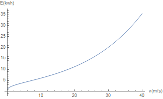
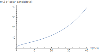
For analysis purposes we first limit ourselves to a single robot(so [math]\displaystyle{ n_{robots}=1 }[/math]). This gives the following graph:
The graph can be divided into 3 sections: the start, the roughly linear middle, and the the quadratic tail. At extremely low speeds the energy needs of the robot will drop tremendously. A large part of the energy need that remains comes from the rolling friction caused by moving the weight of the water.
Note that the mass of robot can be approximated by [math]\displaystyle{ c*\frac{1}{v} }[/math] for small [math]\displaystyle{ v }[/math](with [math]\displaystyle{ c }[/math] a constant). This is a result of the constant we see in the numerator of our formula. The number of trips per day we achieve with this speed is linear in [math]\displaystyle{ v }[/math], since twice the speed results in twice the distance traveled. So we would then get [math]\displaystyle{ c*\frac{1}{v}*v }[/math] mass kilometers, meaning that the energy needed for the rolling friction can be approximated with a constant for very small [math]\displaystyle{ v }[/math]. Note that this is only an explanation of why the model gives this behaviour, and it does not mean that the model this behaviour is correct. The most likely explanation for why these factors come together like this is that one or more of the assumptions we have based our mass estimate on fails for small [math]\displaystyle{ v }[/math]. Note that the air resistance is negligible at these speeds so can be ignored in our analysis here.
In the middle section our energy need goes up roughly linearly. This is because air resistance does not yet play a significant role in this part of the graph. The increase in energy will come purely from needing to do more trips whilst mass doesn't go down by a similar factor, leading to more mass kilometers and a higher energy cost.
In the tail of the graph air resistance starts playing a more dominant role, leading a quadratic graph.
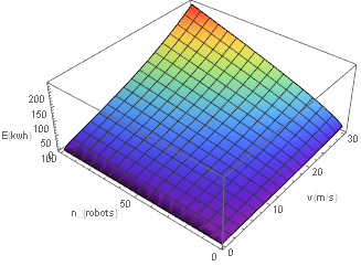
If we start considering the total energy needed by multiple robots we get the following graph:
It should be immediately obvious that more robots will result in higher energy costs. The reason for this can be found in our mass estimate. If we want to cancel out the factor [math]\displaystyle{ n }[/math] that accounts for the fact that we have n robots, we would need our mass to decrease by at least a factor [math]\displaystyle{ n }[/math], but this does not happen. Instead the mass will tend towards a constant function in [math]\displaystyle{ v }[/math] as [math]\displaystyle{ n }[/math] gets larger because of the linear factors in the numerator. The quadratic and higher order factors in v would only make this get worse if we let [math]\displaystyle{ v }[/math] get even larger. Note that the same three stages of the graph can be seen as in the single robot example.
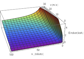
This graph shows the energy needed by just 1 robot if we have multiple robot(so the total energy divided by the number of robots. This graph shows that the energy we need for larger speeds goes up, while the energy needs for smaller robots go down. The reason the graph starts flattening for larger numbers of robots has to be found in the mass estimate: the linear factor in the numerator becomes constant after the division. This constant factor comes from the fact that our wheels give us a constant weight because of our minimum ground clearance. This also results in the other masses getting a constant factor because they are partially dependent on the mass of the wheels.
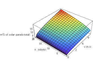
From earlier calculations we already know that 1 [math]\displaystyle{ m^2 }[/math] of solar panels corresponds to roughly 0.9 kwh per day. This graph shows us how much area of solar panels a single robot would need.
This graph shows the same basic behaviour as the energy graph as we would expect. This mostly shows that we can’t go very fast with our robots before the required solar area to power them starts exploding.
If we start considering multiple robots we get a graph similar to that of the energy graph for multiple robots as well
This shows that we need to avoid having too many robots or too fast robots since the energy needs go up quite a bit if we do so. The graph may seem to be slightly different form the energy graph, but that’s only because we zoomed in to exclude parts of the graph that weren’t going to give us a reasonable area because of needing too much energy. Note that in reality we can only deploy a whole number of robots, so not every point in the graph is necessarily possible in reality. Note that whilst our energy needs drop dramatically near v=0, using this would result in massive robots as can be seen in the water and robot mass graphs we’ve shown earlier.
So there is a strong dependencies between the robots size, speed and number of robots. This has been expressed as a formula that determines the robots required size of speed and the number of robots are known. Using this formula and a series of other dependencies/constants we have derived how much energy the robots need to be able to function. From this we could derive how much area of solar panels we need to keep them functioning on a daily energy needs basis. However, some minor factors had been ignored in these calculations, and some of the constants were estimates that may not necessarily be 100% correct for the actual robot made. It would therefore be wise to add a margin of error to the solar area to compensate for this and ensure that we have enough solar panels even if the calculations are a bit off.
In terms of deciding what kind/how many robots to make, three graphs are relevant: The mass of the robot, the mass of the water carried and the solar area. The first two are a good indicator of how large the robot will be. We will want the robot to remain small since that makes it easier to maneuver the robot around in rough terrain. It also ensures that that the system of robots can scale to villages of different size or different distances to the well(note that the latter does need some consideration in terms of battery size if the distance is even larger). Having less robots also ensures that water supply doesn’t stop completely in case one of the robots breaks down.
The third graph we need to consider if the solar area we need to power the robot. If we use more energy we will need more batteries and solar panels, which increase the costs of the robot. This is something we obviously want to keep down as well.
Taking these factors into account, we decided to go for using 5 robots going at a speed of [math]\displaystyle{ 3 m/s }[/math]. The calculations then give a watertank of [math]\displaystyle{ 42l }[/math], a solar area of [math]\displaystyle{ 1.35m^2 }[/math] per robot(and [math]\displaystyle{ 6.8m^2 }[/math] in total).
Note that using more robots does not give an advantage since the size of the water tank is already small enough to allow scaling up and down fairly easily. With the distance of 3000 m to the well, each robot carries about 1000l per day, which gives a decent amount of flexibility. We do not want to make this flexibility in smaller steps since the solar area per robot is independent of the number of robots, so using more robots will rapidly increase the energy we need. Less robots would, however, result in losing too much of this flexibility. For, say, 3 robots we are already looking at 1666 l per day and also more disastrous effects in case a robot fails.
For speed the arguments are similar: higher speed would cost us more energy, less speed would make the robot get larger than we would want without giving us a significant decrease in the energy we need.
The mass estimate of a robot gives is [math]\displaystyle{ 41kg }[/math], of which [math]\displaystyle{ 0.51kg }[/math] batteries in the robot for these numbers. We need to do 24 trips in a day per robot, have 5 robots and need to last for 3 days without charging. The needed energy for a single trip is 0.05 kwh. This means that the charging station needs to have 0.05*24*5*3=18 kwh of capacity.
We get a needed motor power of a bit less than 350w(including the extra power needed to go up inclines). This seems fairly small, but we should consider that the robot moves at low speeds and is fairly lightweight.
Link back to the original page Water Transport Infrastructure
References
- ↑ Engineering ToolBox, (2008). Rolling Resistance. [online] Available at: https://www.engineeringtoolbox.com/rolling-friction-resistance-d_1303.html [Accessed 22/06/2018]
- ↑ Ha, J., Jeong, S., \& Obayashi, S. (2011). Since we have less demands on the shape of the vehicle than a pickup truck due ot not having a driver we can expect that it will be possible for us to take this as an upper bund. Drag reduction of a pickup truck by a rear downward flap. International Journal of Automotive Technology, 12(3), 369.
- ↑ Engineering ToolBox, (2004). Electric Motor Efficiency. [online] Available at: https://www.engineeringtoolbox.com/electrical-motor-efficiency-d_655.html [Accessed 23/06/2018].
- ↑ Battery university. (2018, 31 mei). Types of Lithium-ion batteries. Geraadpleegd op 23 juni 2018, van http://batteryuniversity.com/index.php/learn/article/types_of_lithium_ion
- ↑ rat-holland. (refenced on 24-06-2018). https://www.rat-holland.nl/Elektrische-Fietsen/Motoren/24Volt-250Watt-velgrem-motor
- ↑ fiesunie. (referenced o 24-06-2018). https://www.fietsunie.nl/Middenmotor-Bafang-BBS01-250W
- ↑ SuperRobotDroids. (referenced on 24-06-2018) https://www.superdroidrobots.com/shop/item.aspx/robot-drive-wheel-10-inch-pneumatic/1516/
- ↑ AndysAutosport. (referenced on 24-06-2018). https://www.andysautosport.com/learning_center/buyers_guides/wheel_weights/
- ↑ WhatIsCurbWeight (referenced on 24-06-2018)http://whatiscurbweight.com/vehicle-weight/toyota_curb_weight.htm
