Mobile Robot Control 2021 Group 8
Group information
Group members
| Name: | Student ID: | Email: |
| Rick Peeters | 1021754 | r.peeters@student.tue.nl |
| Rinse Hobma | 1022328 | r.hobma@student.tue.nl |
| Bram Odrosslij | 1016625 | b.odrosslij@student.tue.nl |
| Abdullah Cosgun | 1020574 | a.cosgun@student.tue.nl |
| Ivo Mix | 1011609 | c.g.mix@student.tue.nl |
Tutor
| Cesar Lopez Martinez | c.a.lopez.martinez@tue.nl |
General planning
Week 1 (19 April - 25 April)
- Start with tutorials.
- Prepare the software (Ubuntu, qtcreator, .. ).
- Design document.
- Project planning.
Week 2 (26 April - 2 May)
- Introduction meeting with the tutor.
- Watch tutorials 1.1, 1.2 & 1.3.
Week 3 (3 May - 9 May)
- Deadline: Design document (4 May)
- Finish the tutorials.
- Watch tutorials 2.1, 2.2 & 2.3.
- Orientating the escape room challenge.
Week 4 (10 May - 16 May)
- Finish the script for the escape room competition.
- Escape room competition (12 May)
- Evaluating the result of the escape room competition.
Week 5 (17 May - 23 May)
- Start oriëntating for the hospital competition.
Week 6 (24 May - 30 May)
Week 7 (31 May - 6 June)
- Presentations (2 June)
Week 8 (7 June - 13 June)
- Final Competition (9 June)
Week 9 (14 June - 20 June)
Week 10 (21 June - 23 June)
- Deadline: Wiki pages (23 June)
Course description
Introduction
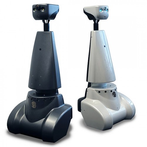
At this wiki page a complete project overview of the course Mobile Robot Control of group 8 is presented. The goal of this course is to control the movement of a robot, called PICO, by using only raw sensor data. The software that was used for this is written in C++. In this chapter a brief introduction will be given about the robot itself, the assignments that it needs to perform and function requirements in the form of a design document. In the next chapters a complete elaboration of both assignments will be given, in which the exact tasks will be described as well as the software structure that was used. Based on the performance during the assignments a conclusion will be drawn for both assignments. Unfortunately, due to the Covid-19 measures, the implementation and execution will be in a completely simulated environment.
PICO
As mentioned above the robot that will be used is called PICO, which is shown in Figure 1. It has 3 omni wheels which together form a holonomic base, meaning it can move in both x- and y-direction, as wel as rotating around the z-axis. This rotation will be called theta in the remainder of this wiki page. The relative position with respect to its starting position can be determined with odometry data, however there is drift in this data which accumulates over time. It is also equipped with a Laser Range Finder (LRF), to scan its surroundings. With the system the distance towards walls and (moving) objects can be determined over a certain range.
Assignments
Escape Room Challenge
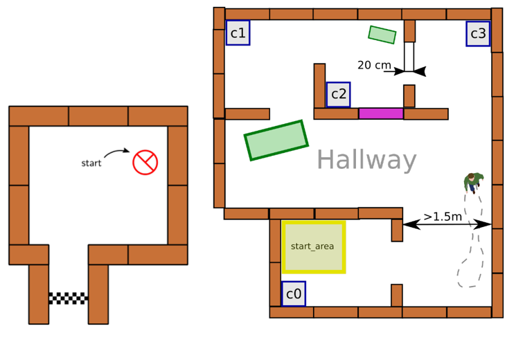
The goal of the escape room challenge is to let PICO escape a room that is approximately rectangular, and has one corridor placed at a random position. The dimensions of the room and the width of the corridor are both unknown. The starting position and orientation of PICO is also random. If it drives through the corridor within 5 minutes the assignment is passed.
Hospital Challenge
For the hospital challenge, PICO needs to drive through a hospital environment with multiple rooms and hallways without causing collisions. There are also static and moving objects that it needs to avoid. The ultimate goal is to drive to a number of cabinets in a predefined order to get or drop off medicines. Because PICO does not have the ability to actually grab something, it is sufficient for this assignment to face the cabinets for a while and then drive to the next one. The goal is reached when all the cabinets were reached within a certain time and without crashing to walls or objects.
Design document
The design document describes the initial idea for the solutation on the basis of the requirements, functions, components, specifications and interfaces.
The design document can be found here.
Escape Room Challenge
Strategy
The basis of the used strategy for the escape room challenge lies in the Artificial potential field algorithm. Together with the Finite state machine, that is defined in the design document, and the exit detection algorithm, forms this the strategy that is used in the escape room challenge.
Finite state machine (FSM)
..

The basis of the navigation module lies on the artificial potential field algorithm. This algorithm uses two vectors that determine the motion of the PICO robot. The first vector is the attractive vector, which is determined by the difference in the current position of the robot and the target position that is determined by the exit detection algorithm. The other vector is the repulsive vector, which makes the PICO robot move away from the wall and is proportional to the distance from the PICO robot to the wall. This means that the magnitude of the vector increases when the PICO robot is closer to the wall.
The path of the PICO robot is then determined by taking the sum of attractive vector and the repulsive vector. By updating these vectors with a frequency of 20 [Hz], the PICO robot will move in the direction of the target point while at the same time getting pushed away from the wall.
While implementing this algorithm, the group ran into difficulties and the navigation module was changed. The start of the algorithm, in which the robot drives in the direction of the target point, stayed the same.
The difference in the algorithm was made in de part where the robot approaches the wall near the exit. When this happens the PICO robot moves, parallel to the wall at a fixed distance in the direction of the target point. This procedure happens until the PICO robot is located in the corridor. The idea behind locating the robot parallel to the corridor is that this way the robot does not lose sight of the exit point, which happened during testing. Eventually when the robot has passed the corner, the robot will be attracted to the target point and drive in that direction.
Exit detection
..
Testing
A big part in the process of making the algorithm for the escape room challenge, is testing. This is therefore done thoroughly with multiple maps with each different properties to tackle problems that can occur during the actual escape room challenge.
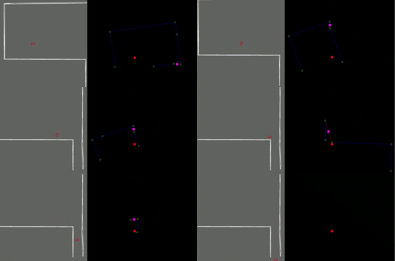
To help understand what the robot sees, a visualization is made with the tools available in OpenCV. In these visualisations multiple objects can be identified. The blue lines represent the walls of the room, the green circles represent the end of line segments and corner points. The red dot is PICO robot itself and the pink dot is the target whereto the robot is driving.
First test map
The first map has its exit in the vertical direction at the top left. The exit is not aligned with the wall on the left side. In the simulation in Figure 2 can be seen that the robot first drives to the pink dot, but when it almost touches the wall, it aligns itself with the exit direction and drives sideways to the beginning of the corridor, after which it drives itself to the exit.

Second test map
The second test map has its exit in the vertical direction at the bottom right corner, with the exit being aligned with wall on the right. The movement that the robot uses is the same as in the previous test map and shows that the algorithm does not have an issue with an exit that is aligned with a wall.
Third test map
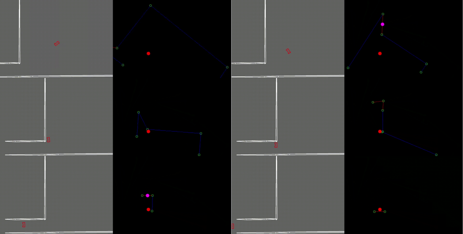
The third map has its exit in the horizontal direction at the bottom left corner. In the simulation in Figure 4 can be seen that the algorithm has no issue detecting the target point and driving in that direction. The robot does has some issues with passing the corner of the exit, because it loses track of the target point, but eventually finds the target point again at the end of the exit and drives to it. This simulation gave already a heads up that the algorithm could have some problems in the escape room challenge.
Fourth test map
In the Figure below the simulation of the fourth map is shown. In this simulation a problem reveals itself, because the robot keeps rotating on its starting spot, while it does recognize the target point. After evaluating this problem, it was determined that this behaviour was caused by the finite state machine, in which it was stuck in the ‘rotate’ state. Unfortunately this problem was not solved before the escape room challenge in which the same behaviour occurred, which can be seen in the next paragraph.

Result Escape Room Challenge
In the Escape Room challenge, the same behaviour happened as in the simulation with the fourth test map. The algorithm detects the exit, which can be seen in the visualization, but it does not drives towards it. The escape room challenge therefor was a great lesson in the robustness of the algorithm. The algorithm needs to be prepared for every possible situation that can occur and needs to be tested thoroughly to tackle all these situations.

Hospital Challenge
Strategy
Finite State Machine
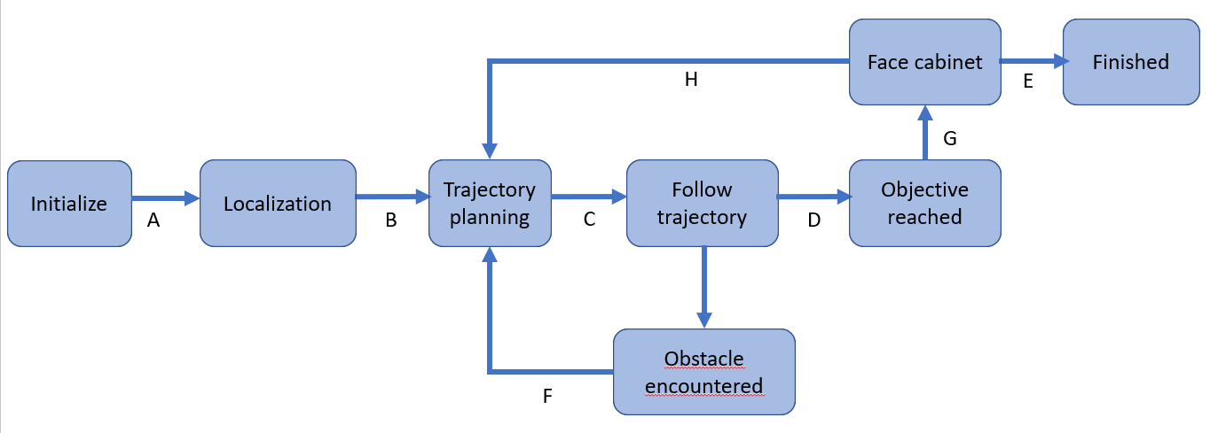
INITIALIZE:
LOCALIZATION:
TRAJECTORY PLANNING:
FOLLOW TRAJECTORY:
OBJECTIVE REACHED:
FACE CABINET:
OBSTACLE ENCOUNTERED:
FINISHED:
A:
B:
C:
H:
D:
E:
F:
G: