Integration Project Systems and Control 2013 Group 4
Jump to navigation
Jump to search
Group Members
| Name: | Student id: | Email: |
| Koen Gruntjens | 0760934 | k.g.j.gruntjens@student.tue.nl |
| Erik van Broekhoven | 0637413 | e.c.v.broekhoven@student.tue.nl |
| Wouter Geelen | 0744855 | w.geelen@student.tue.nl |
| Leroy Hazeleger | 0651762 | l.hazeleger@student.tue.nl |
Planning
February 18 - February 24
- Qualitative analysis of robot
- Derivation of kinematics and dynamics
- Preparation of first experiment session
- Investigate different control-design
- Group meeting
February 25 - March 3
- FRF-measurement and analyse
- Coupled/decoupled experiment
- Non-linearity experiment
- Static friction experiment
- Group meeting
March 4 - March 10
- Continue making FRF-measurements
- Design PID controllers for all joints
- Trajectory planning for all joints
- Group meeting
March 11 - March 17
- Verify trajectory planning (minimum time trajectory)
- Optimization of PID controller
- Group meeting
March 18 - March 24
- Design feedforward controller
- Implementing feedforward controller
- Discuss and design ILC
- Group meeting
Progress
Week 1
- The first step in this project was to identify the pizza-robot by creating a list of all the design requirements of the pizza-robot (to design experiments) such as:
- The pizza is not allowed to fall during transport, therefore the maximum acceleration in directions is limited.
- The robot is not allowed to touch the pizza holding brackets, therefore the trajectory must be designed in such a manner that the pizza-robot does not collide with the brackets.
- 3 pizza's must be transported and the pizzas must be transported as fast as possible (approx. 10-15 [s]). To achieve this a good controller and trajectory for axis have to be designed.
- The controller must be stable.
- The output of the controller is limited for each axis i.e. we are dealing with saturation.
- The accuracy of the pizza-robot end-effector when obtaining a pizza from the brackets should be approximate 5 [mm].
- Identifying limitations of the pizza-robot such as:
- Degrees of freedom to specify the work space of the end-effector.
- Possibly non-linear coulomb and viscous friction.
- The maximum input signals [V] of the motors of the pizza-robot and consequently the maximum velocity/acceleration of each joint.
- To identify the pizza-robot in a more specific way:
- The kinematics of the pizza-robot are derived which are helpful for the trajectory design and determining the dynamics of the pizza-robot using the DH convention.
- A simple model of the pizza-robot is determined to possibly use model-based control design (dynamics of the pizza-robot in terms of the generalized coordinates is difficult, consider a simple model for each joint separately)
- FRF-measurement experiments are prepared (designing a reference trajectory, a stabilizing controller)
- Different types of feedback-control are considered which are usable (and possible with the knowledge of the groupmembers)
Week 2
- As already mentioned in week 1, a simple model is proposed to (possibly) use for model-based control design instead of the dynamics of the pizza-robot in terms of its generalized coordinates since this is too complex and not usable as model-based control design. (for every joint a model, with disturbances from other joints)
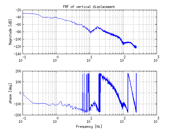
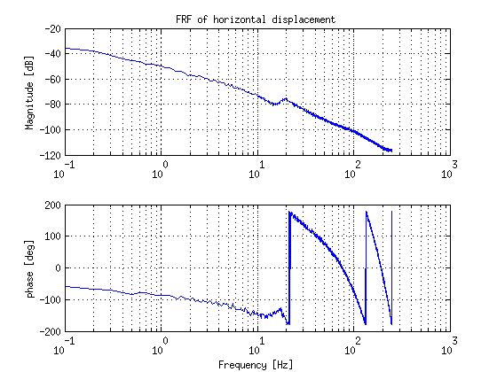
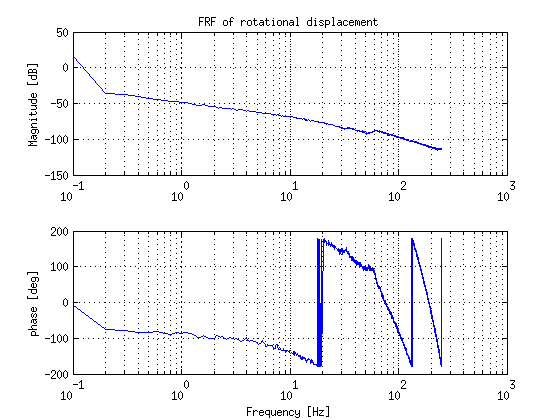
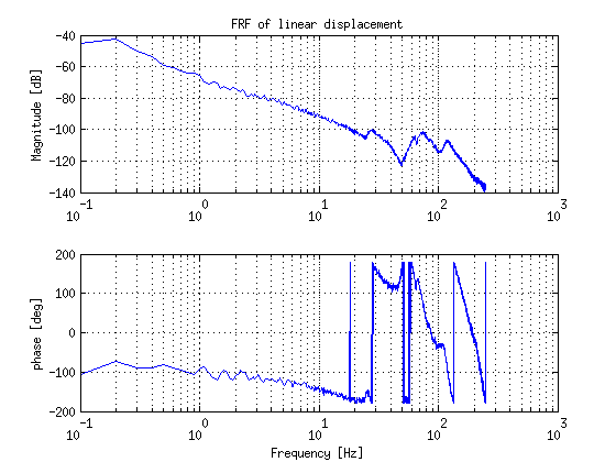
- FRF-measurements are performed of each joint with a stabilizing controller and a specific reference trajectory, however large friction is encountered which seems to be not constant along the trajectory of each joint. This influence the FRF-measurements at low frequency. (improve FRF-measurements)
- The deadzone of each axis have been determined.
- It has been determined that the pizza-robot can be treated as a system that is decoupled.
Week 3
- It took a bit more time for doing the FRF-measurements. Finally we have all FRF's of the joints and all group members designed a stable controller for two joints e.g. such that every joint had at least two controllers made by 2 different members of the group.
| Vertical displacement | Horizontal displacement |
|
|
| Rotational displacement | Linear displacement |
|
|
Week 4
- The controllers designed last week did not meet all the requirements. Therefore they have been redesigned. Next week they will be verified and further improved.
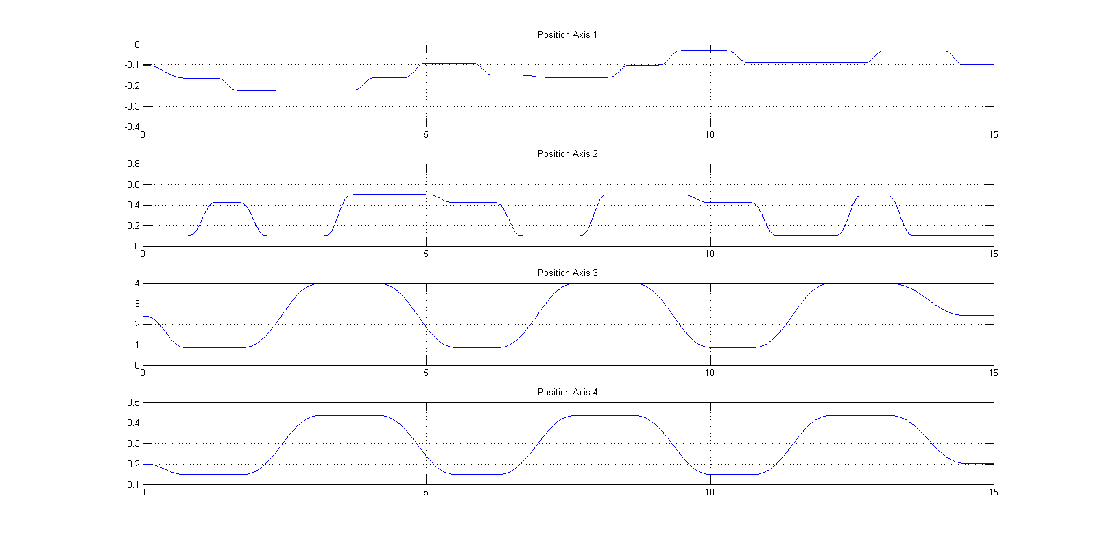
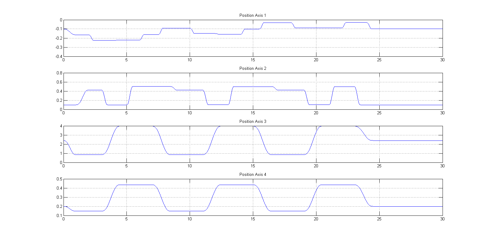
- There was some discussion about whether we should create the reference trajectory with the ref3 block or by using the technique trajectory for point-to-point motion. It was decided that we would choose for the latter. This was decided because when we would use the ref3 block we had to program the whole trajectory in this block while the other technique allows more flexibility i.e. we only have to program the movement of bringing a single pizza to the other shelve. Using a offset in the height of the horizontal axis we can then also transport the other two.
Week 5
| Fast Trajectory |
|
| Slow (safe) Trajectory |
|
Week 6 & 7
- Implementing the trajectories and optimization of the controllers
- A video of performing the fast trajectory in 14 seconds: Video