Football Table Table
How it works
The semi-automated foosball table four 2DOF rods, these are actuated using two rotary actuators:
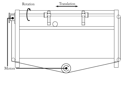
The lateral actuation uses a cable wound around a pulley underneath the table, pulling the puppets back and forth across a rotating axle. This axle is rotated using a set of sprockets on the side of the table.
MOTION_DEMO
MOTION_DEMO is the most basic variant we can run on the table. This uses mostly old files and the old policy (just kicking the ball forward). Because the other variants have not been tested enough, it is recommend to compile this one for demonstrations. See Motion section for details on how to use this file.
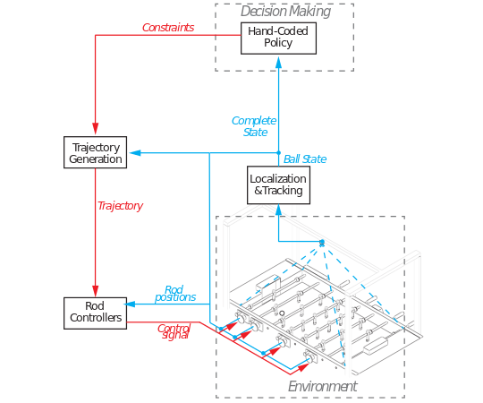
MOTION_DEMOMOTION_EXP
MOTION_EXP has full Reinforcement Learning(RL) capabilities. It concurrently runs the policy of MOTION_DEMO for the midfield and defenders, only the attackers have been hooked up to the RL based policy(bypassing kickround, this needs to be fixed). The reinforcement learning itself works fine, however execution of actions is currently not working smoothly. This has to do with both the detection, execution using the attractor dynamics and the way constraints are calculated. See Motion section for details on how to use this file.
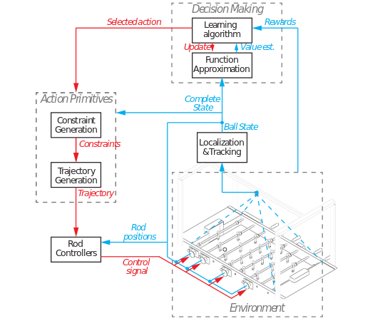
MOTION_EXP and MOTION_TESTMOTION_TEST
MOTION_TEST basically is a stripped version of the above files, which uses simulation only. This can be used to learn new policies, which can later be loaded into MOTION_EXP.
Starting it up
To power up the table:
- First we turn on the power outlet inside the drawer that contains the amplifier.
- Next we can turn on the amplifier by twisting the power knob, you will hear a slight humming noise.
- After this press the blue reset button on the left side of the drawer.
- Make sure that the emergency button is not stuck in a downward position, if so, pull the button up and press the reset button again.
The camera will automatically turn on once it is plugged in, make sure to also turn on the lights and set them to the correct brightness.
Transport
Internal transport is relatively simple using the pallet truck, just make sure all the braces line up correctly with the tables lower frame and jack up the table. It should fit just beneath all doors (in modern buildings). Make sure the drawer is secured using the provided bolt.
When transporting to locations that cannot be reached using the TU/e hallways, we commonly use a small truck. Make sure you have at least one extra person to help you. The average truck will be slightly too low to fit the table with the top attached. Therefore it is wise to remove both the top `hood' containing the lights and the crossmember containing the camera. It is advisable to not remove the two U-shaped frame members, this requires a lot more work and is often not neccesary.
Common causes of error
Here we describe some common causes of error when running the real setup. These errors can occur without actual human errors.
Diagnostics
There is a log file available in the main folder, called
MOTION.mat. Here the measured position and the sent control signal are being logged. Use your control-knowledge and common-sense to examine this data and find the problem.
Poor overal performance
Symptoms: often loosing sight of the ball, missing the ball completely when attempting to shoot.
Bad performance, table soccer-wise is often too to bad detection/calibration. Take into account that changing lighting conditions have a significant impact on the overal performance of the localization. It is not uncommon that lighting conditions change significantly during a day, espicially in a room with direct sunlight.
A quick fix can often be achieved by adjusting the fluorescent lights over the table using the dimmer, to cope with the changed conditions. Similarly adjusting the exposure time (ET) can help. If changing the lighting conditions does not help, then it is advisable to fine-tune the color-calibration itself. When using the white ball, checking and fixing the mask positioning is also advisable.
Sometimes the position of the overhead camera changes during transport, which in turn messes up the camera calibration e.g. the distorion, the mask placement and espicially the rod positions. Symptons of this are e.g. a static offset when trying to hit the ball (whilst detection is good).To fix this one needs to quickly re-run the camera-calibration (not the color-calibration).
Failure in homing
Symptoms: one or more rods fail to reach a central/homed position on the table. However motion during homing is stable and controlled.
Homing is two stage process, first rotational homing takes place after which the lateral direction is homed. Typically failure involves on of the following two cases:
The rod keeps on rotating, stops, and does not finish homing
This is the most common failure, it has to do with the homing sensor. This sensor in the rotational motor frame and detects the passing of a brass insert in the large white sprocket(s). If it succesfully detects this insert passing by, the led on the sensor will light up. If the led does not light up, then the likely cause is that the distance between the insert and the sensor is too large.
This is cause by the fact that there is play in the rotating part of the rod, neccesary to keep the friction down. If we gently pull the rod towards the sensor and restart the homing, the problem will often be solved. You can test this without starting the
MOTIONexecutable, all that is needed is to have the amplifier on, by manually rotating the rod past the sensor and checking if the led lights up.The rod finishes homing, but does not reach a central position
The lateral homing is based on (control) error, as soon as the error builds up above a threshold set in
MOTION.mdlit assumes it has reached the side of the table. If it moves towards the middle before actually reaching the side of the table, this threshold needs to be tuned.If it does high the side of the table but does reach a central position, you can adjusts the lateral position in
MOTION.mdlIf the rotational homing does not reach a completely upright position (before moving back slightly), you can adjust this position in
MOTION.mdlas well.
Loose sensor cable
Symptoms: puppet slams into the wall or spins out of control during run-time or homing,
motion.matshows encoder output to be zero.A loose sensor cable will cause a dramatic failure, but will also show a sensor read-out of zero. Securely reconnect the cable and make sure the failure did not damage any other parts of the system (especially the cable).
Missed interrupts
Symptoms: puppet vibrates heaviliy or slams into the wall or spins out of control during run-time or homing,
motion.matshows instability.Missed interrupts are reported when the
MOTIONexecutable finishes, a high number/percentage of interrupts will cause instable behavior. Missed interrupts occur when theMOTIONexecutable fails to hit the real-time deadlines. This can be caused by excessive computational demand inMOTIONor failure to set real-time priorities for this executable. Locate the source of error and make sure the failure did not damage any other parts of the system (especially the cable).
Instable Controller
Symptoms: same as missed interrupts, without the report of missed interrupts
This setup is sensitive to wear, which can cause the controllers to become instable. To fix this first make sure the failure did not damage any other parts of the system (especially the cable). If all is well the controllers need to be redesigned, for controller design compile and use
MOTION_FRF.mdl, in the tools folder a m-file is provided which can use the data generated to estimate the plant transfer function. During this measurements make sure to use very conservative controllers, read up on the main cstwiki page's documentation to refresh your knowledge.
Segfault from motion
If motion instantly segfaults when you attempt to run it, make sure you have an ethernet connection. Also make sure the amplifier is properly turned on and the emergency stop button is not down and press reset. If this does not fix things try restarting the amplifier, otherwise you should examine your code(segfault commonly come from memory errors (i.e. bad pointers))
Maintenance
In this section describes what to do when maintenance is required.
Replacing a cable
Cables often wear out and eventually snap, also sometimes cables can get wound up by a failure and deform. Replacing cables is a tedious job, in this section some pictures are included describing the process step by step.
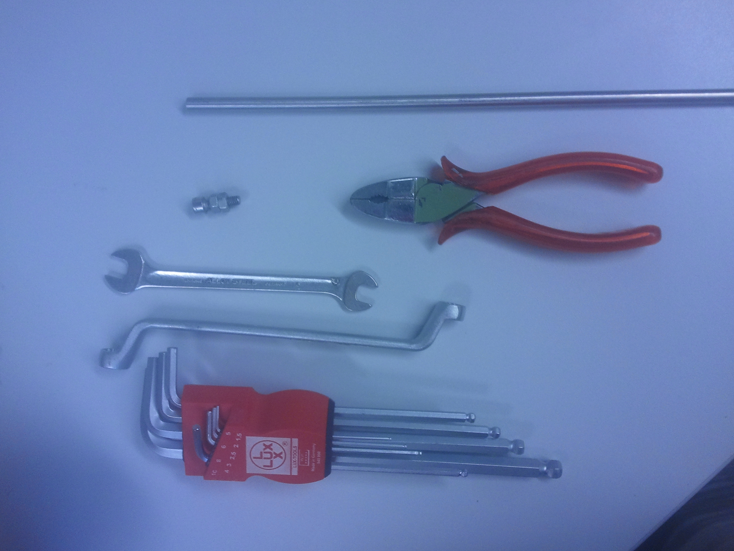
Tools required
Below is a picture of the tools required to replace a cable.
Removing the old cable
- First start by undoing the cable from the pulley below the table using the Allen-keys.
- If the cable has failed it can also be easy to simply cut the wire.
- If the cable is complete entangled around the pulley, it is often easiest to remove the actuator all together.
- In some cases it requires removing the pulley from the actuator (borrow a pulley-puller from the DCT workshop).
- Undo the clamp/key
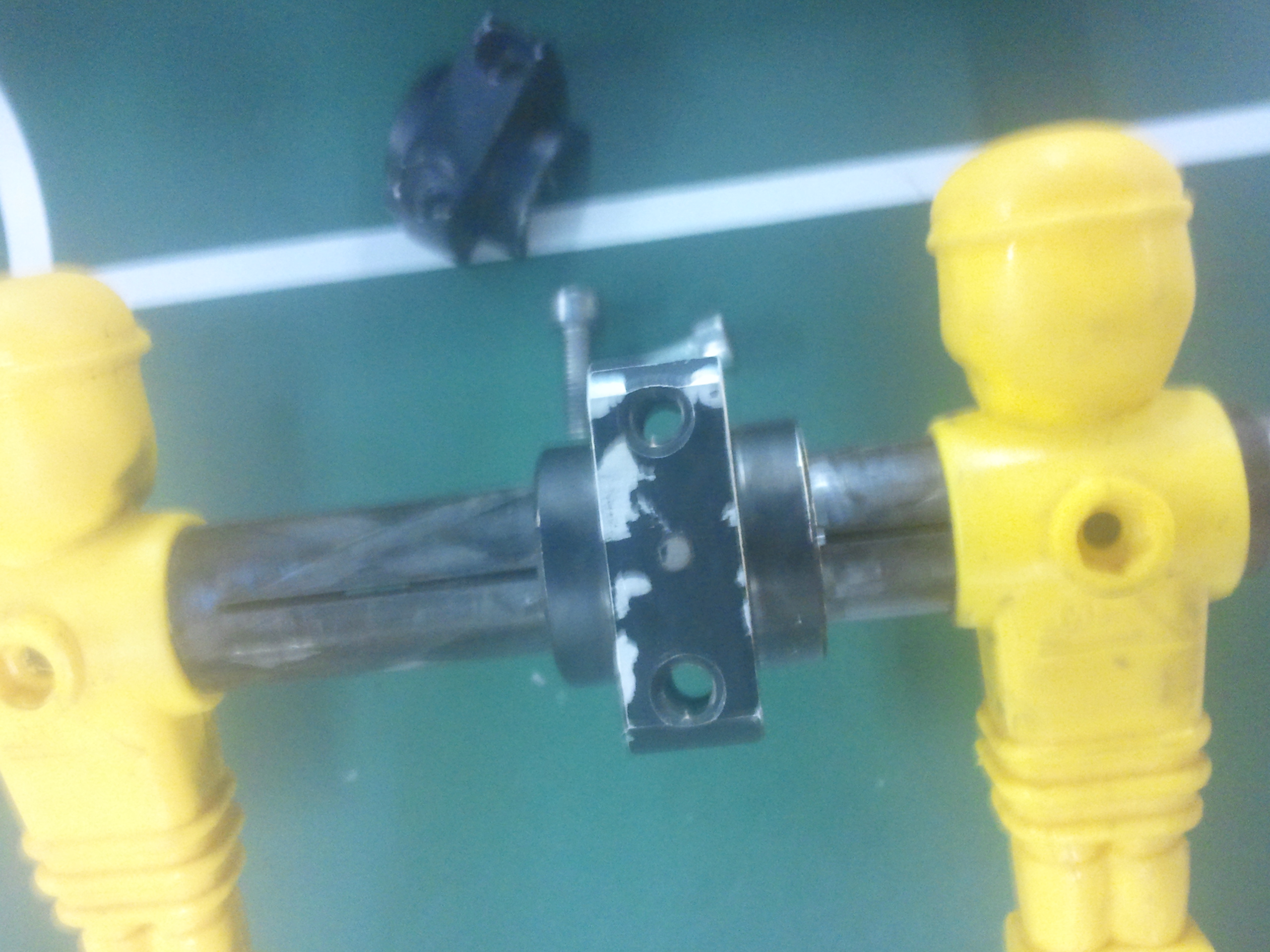
- Next start undoing the part holding the small pulley in place:
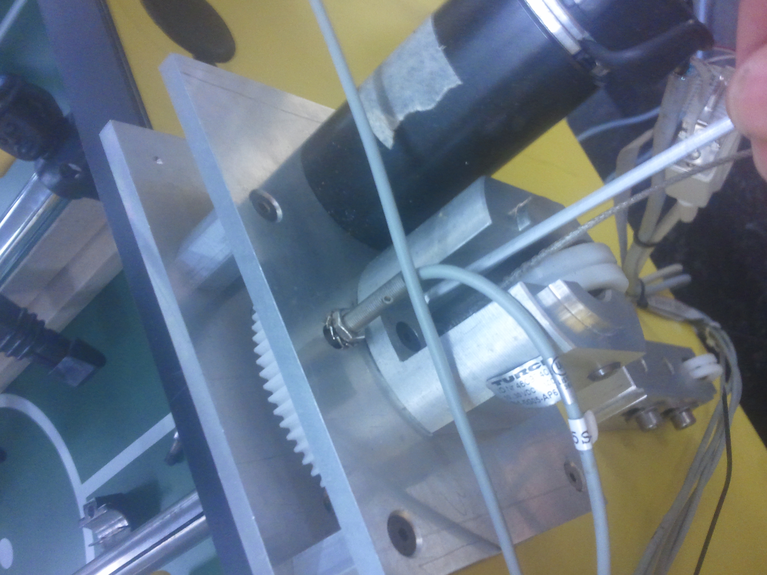
Undo the central bolt 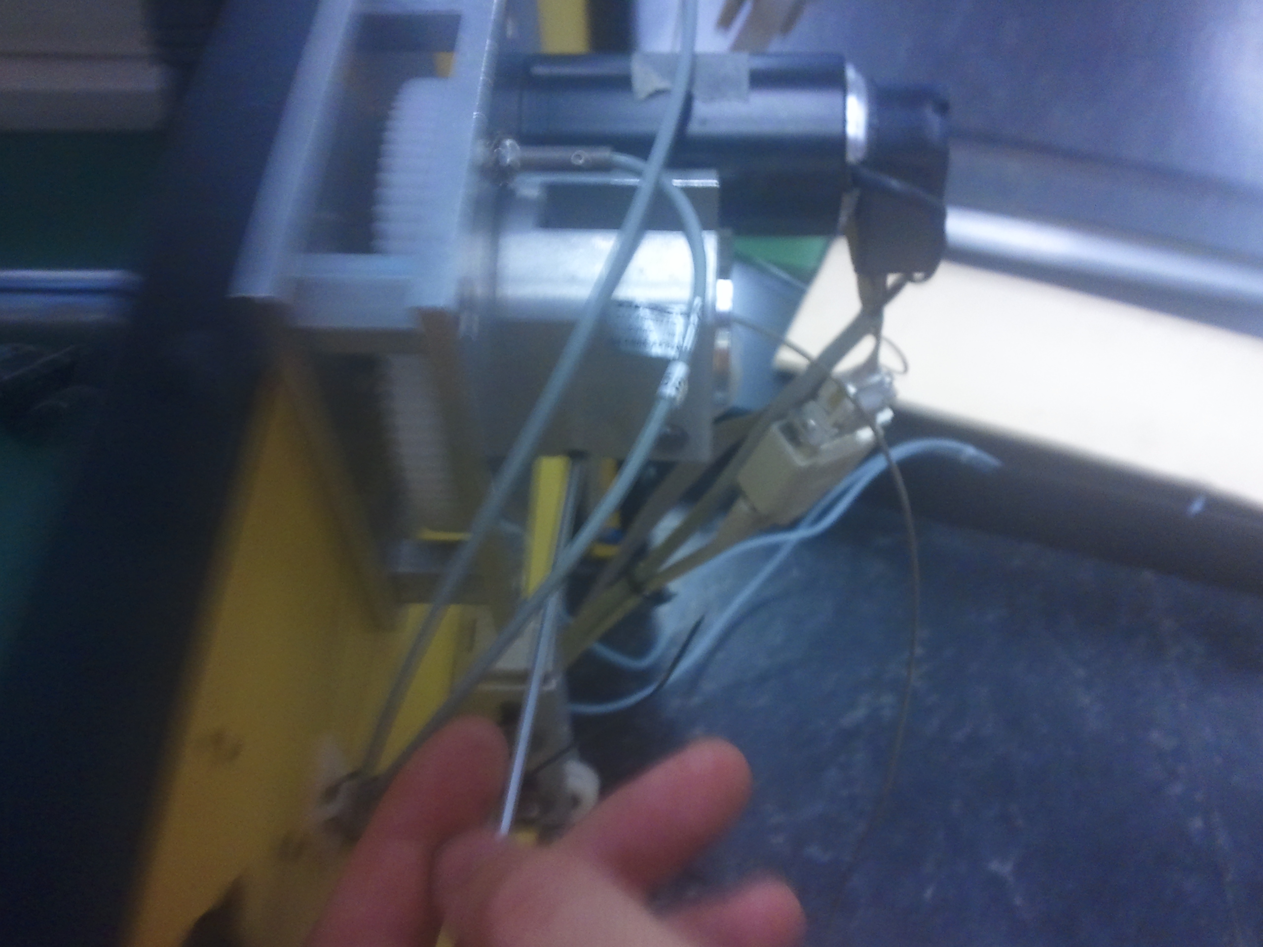
Loosen the alignment bolt on one side - Now remove the bracket and pull out the cable
- You are left with a cable clamped in a 'key-seating':
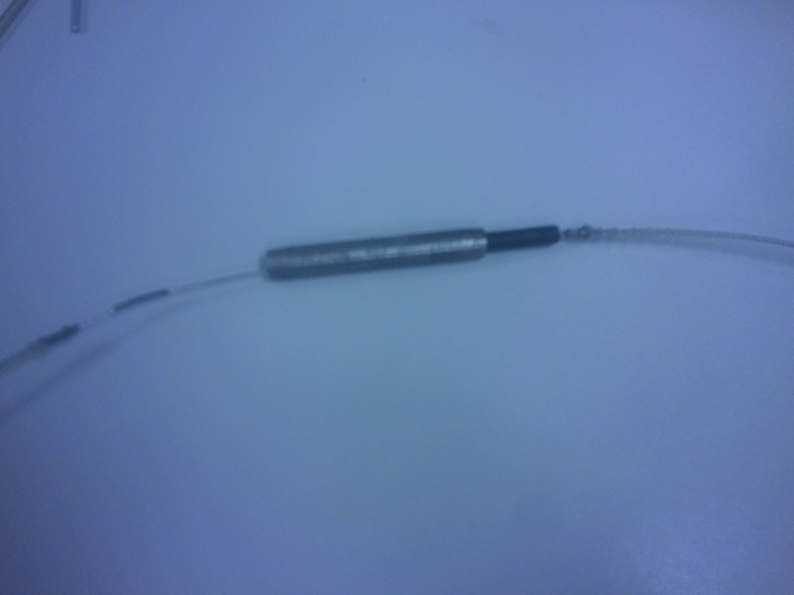
Cable and key-seating - Attach the two bolts to the thread (tighten firmly against each other using the spanners):
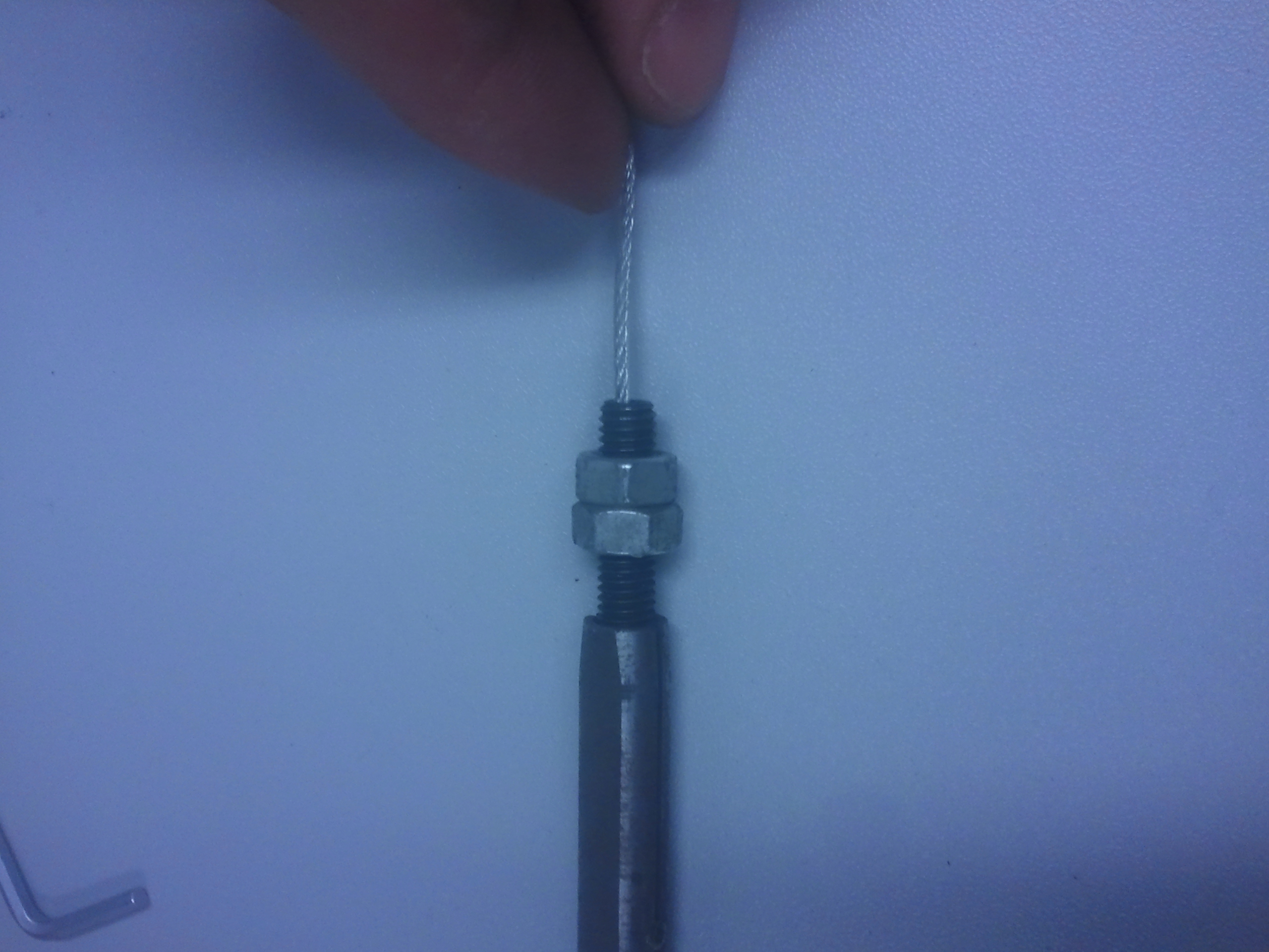
Undo the central bolt - Now use the pliers and one of the spanners and undo the thread from the key-seating:
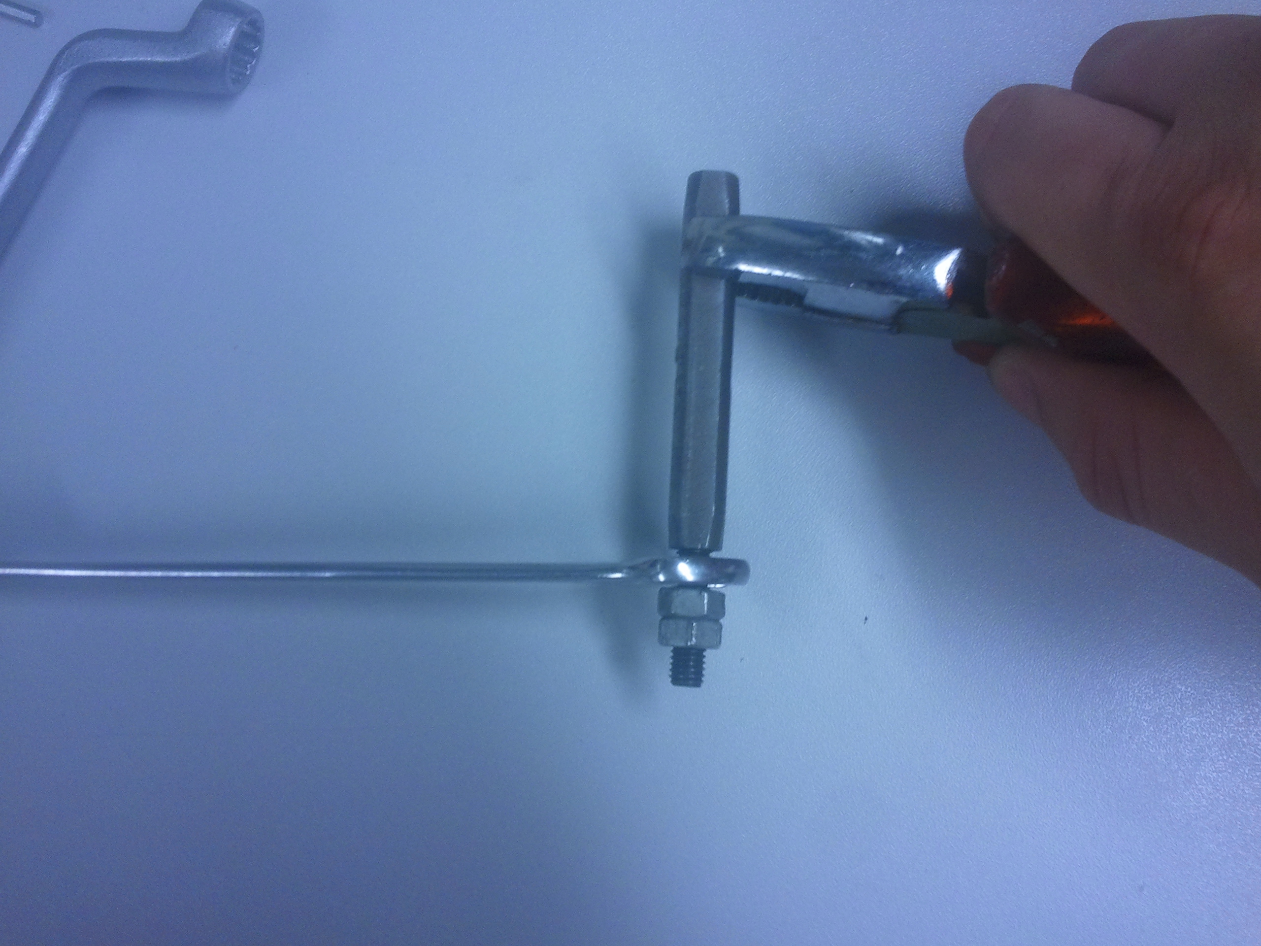
Undo the thread (normally there would still be a cable attached here) - Remove the old cable
Attaching the new cable
- Insert the new wire, locking up the metal clamped on the center of the cable:

Add the new wire to the detached key-seating - Now reattach the thread (feed the wire trough) and tighten:
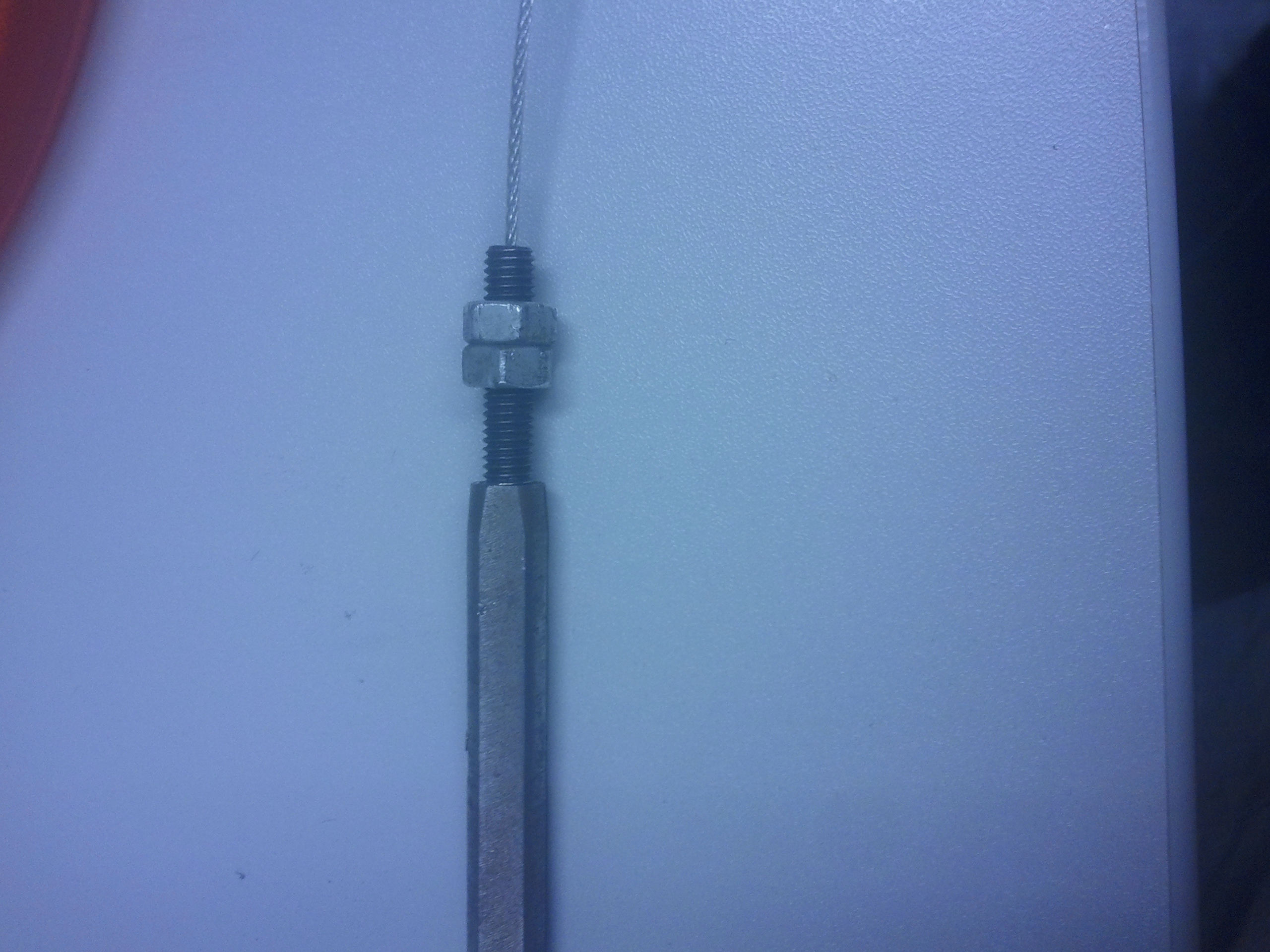
Reconnect the thread - We are now done attaching the wire, next we re-connect it to the puppets. To do this, connect the new assembly to the provided metal rod (feed the wire trough):
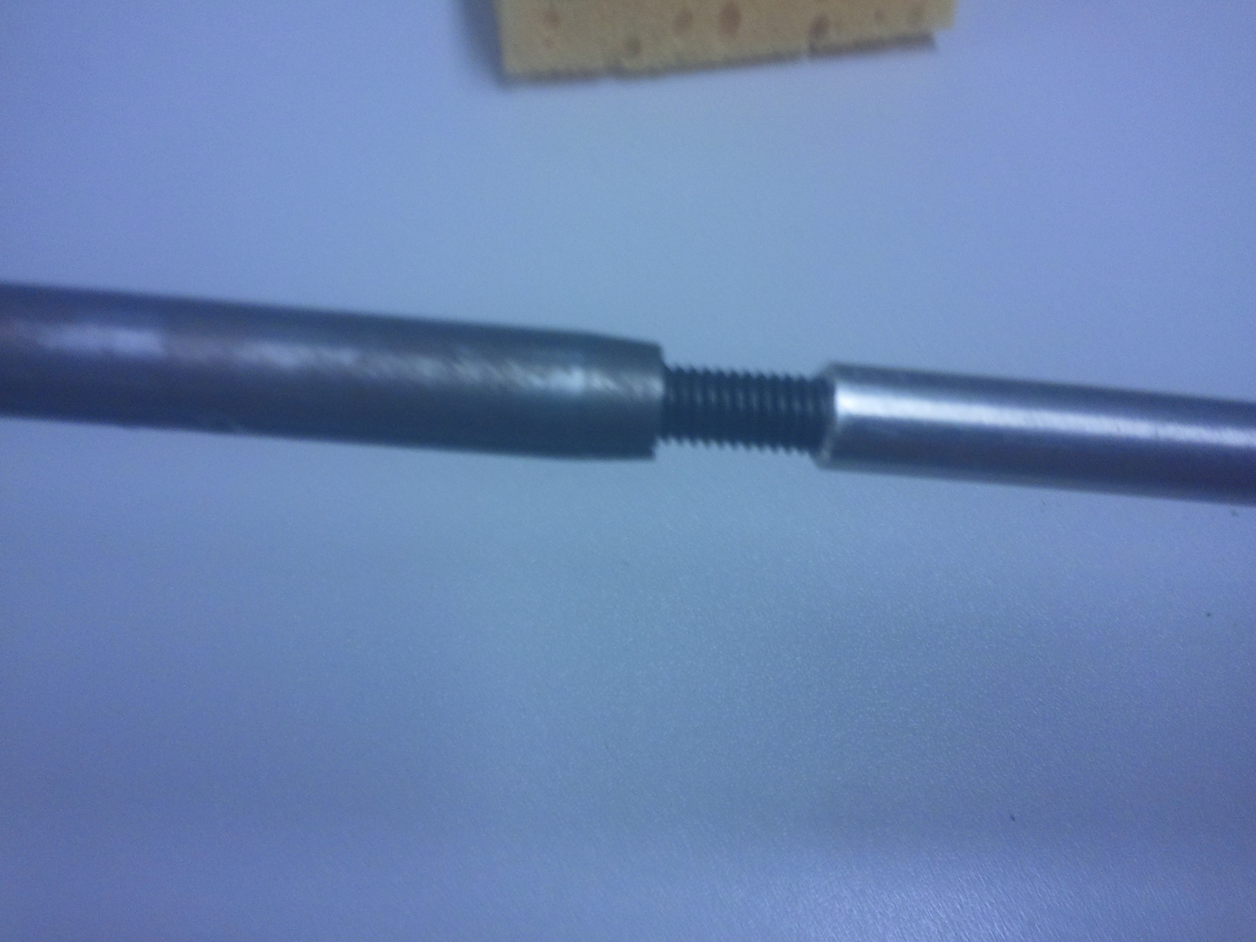
Connect the assembly to the rod - Now push in the wire using the rod and position near where cable is connected to the puppets:
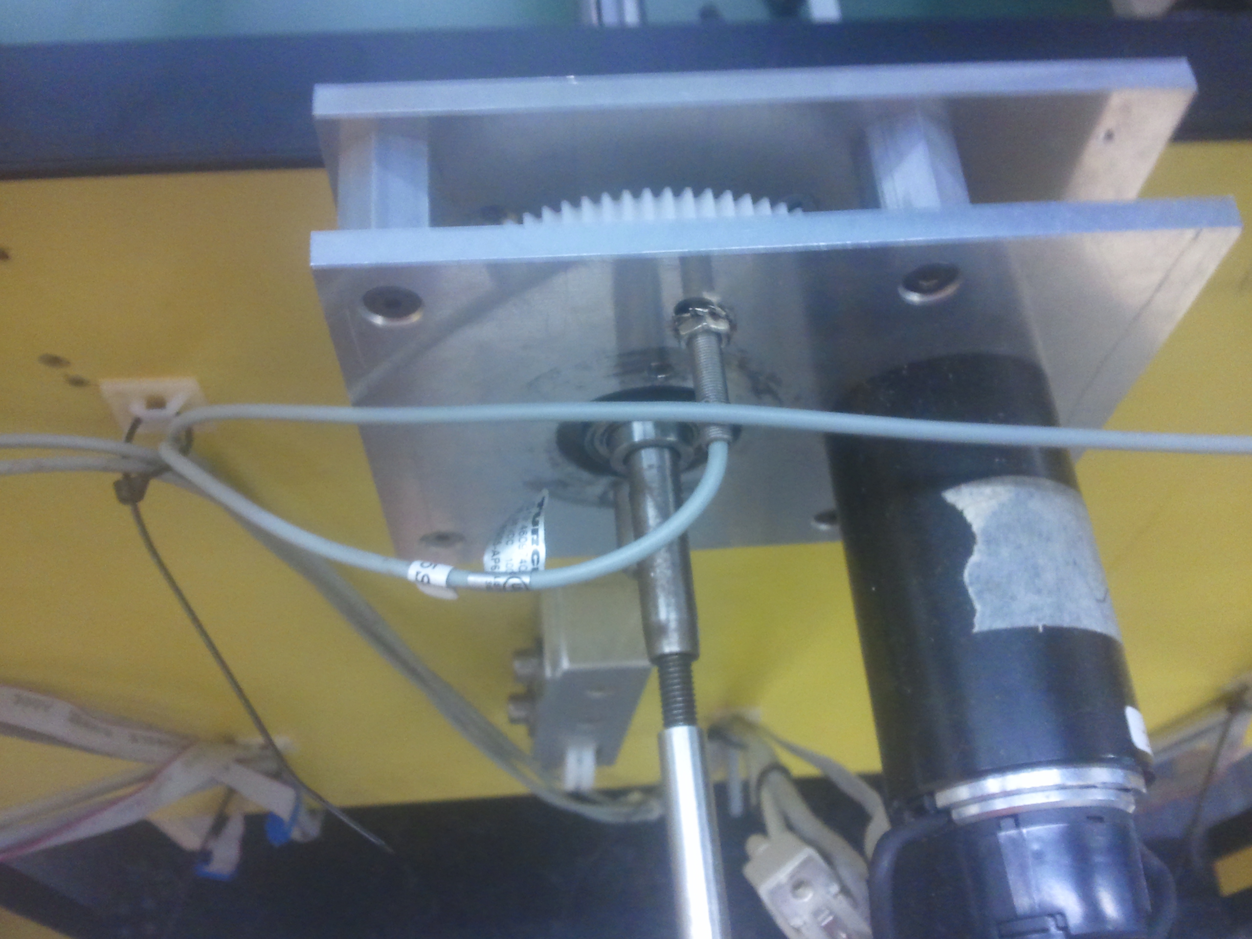
Push in the rod - Now carefully line up the slot in the key-seating with the slot in the carbon part on the puppets:
Line up key-seating - Now place on one half of the clamp/key, note there is a small cut-out on the clamp(key), this should go around the bolt in key-seating. If succesful, the clamp should sit close to the carbon tube:

Reattach the key (test by moving it back/forth) - Connect the other side carefully and tighten:
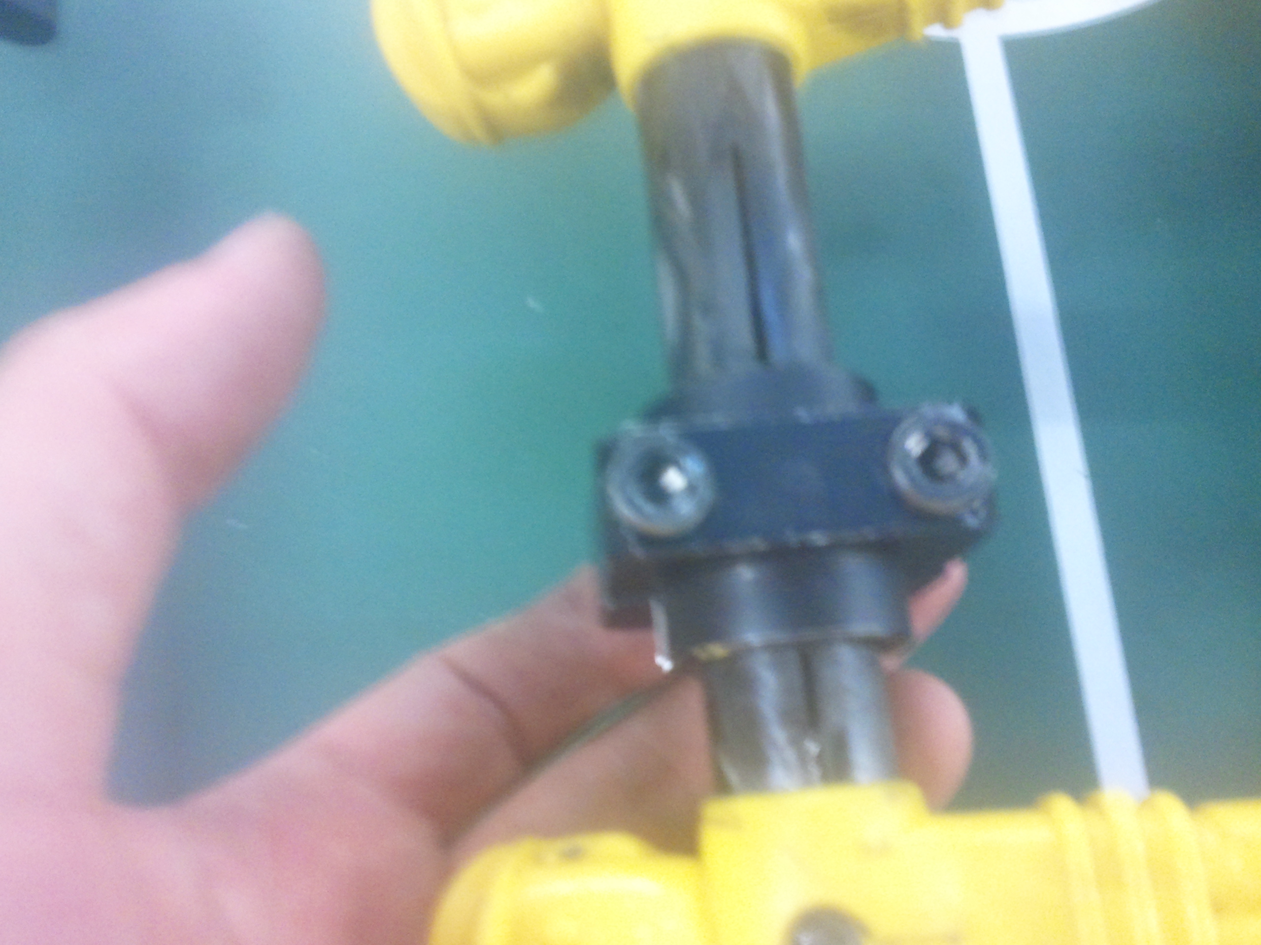
Attach the other side - Now remove the rod used for positioning the key-seating
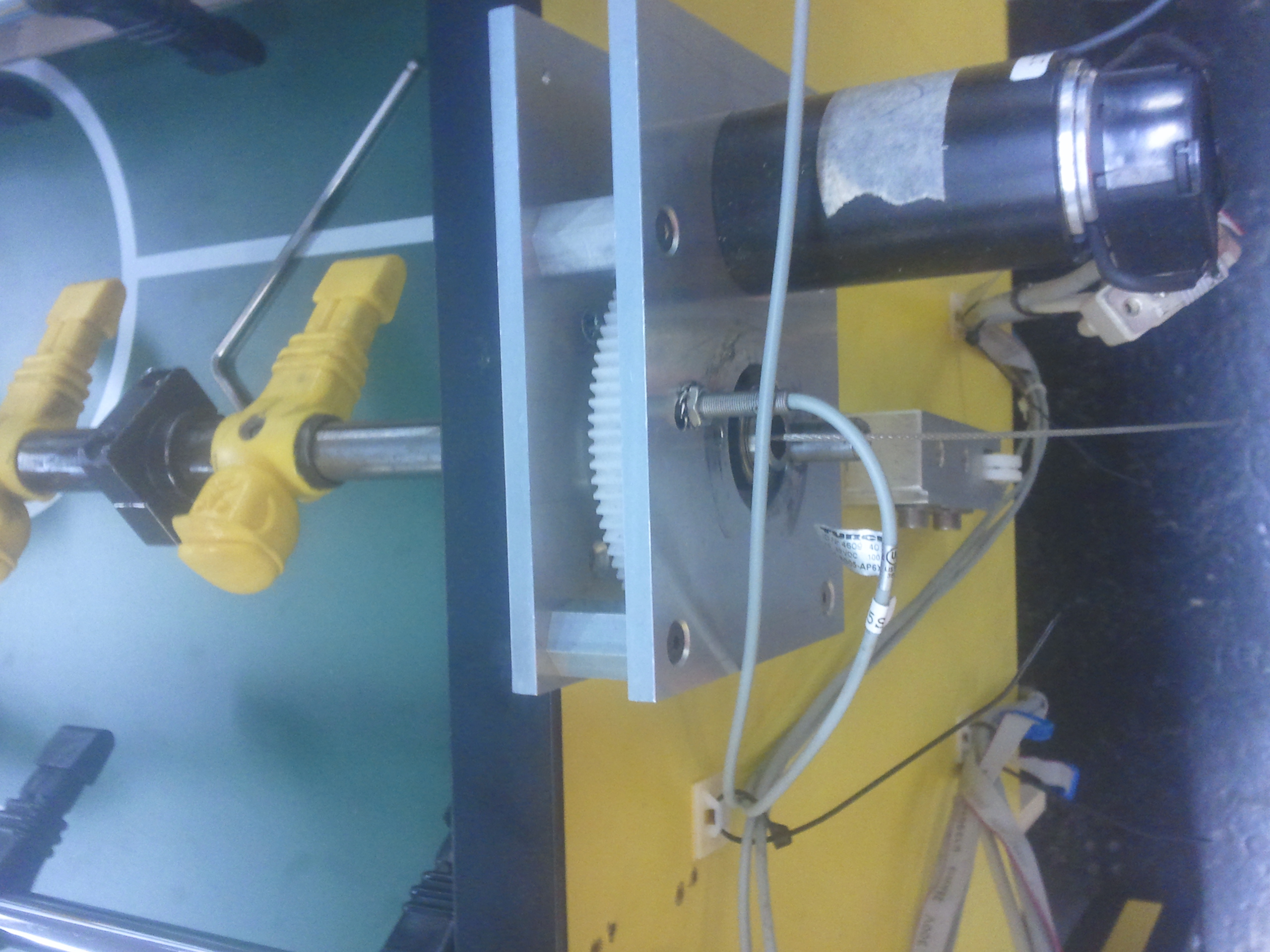
Wire is now connected - Reattach the part holding the pulley, make sure to tighten the alignment bolt (make sure the sprockets turn smoothly).
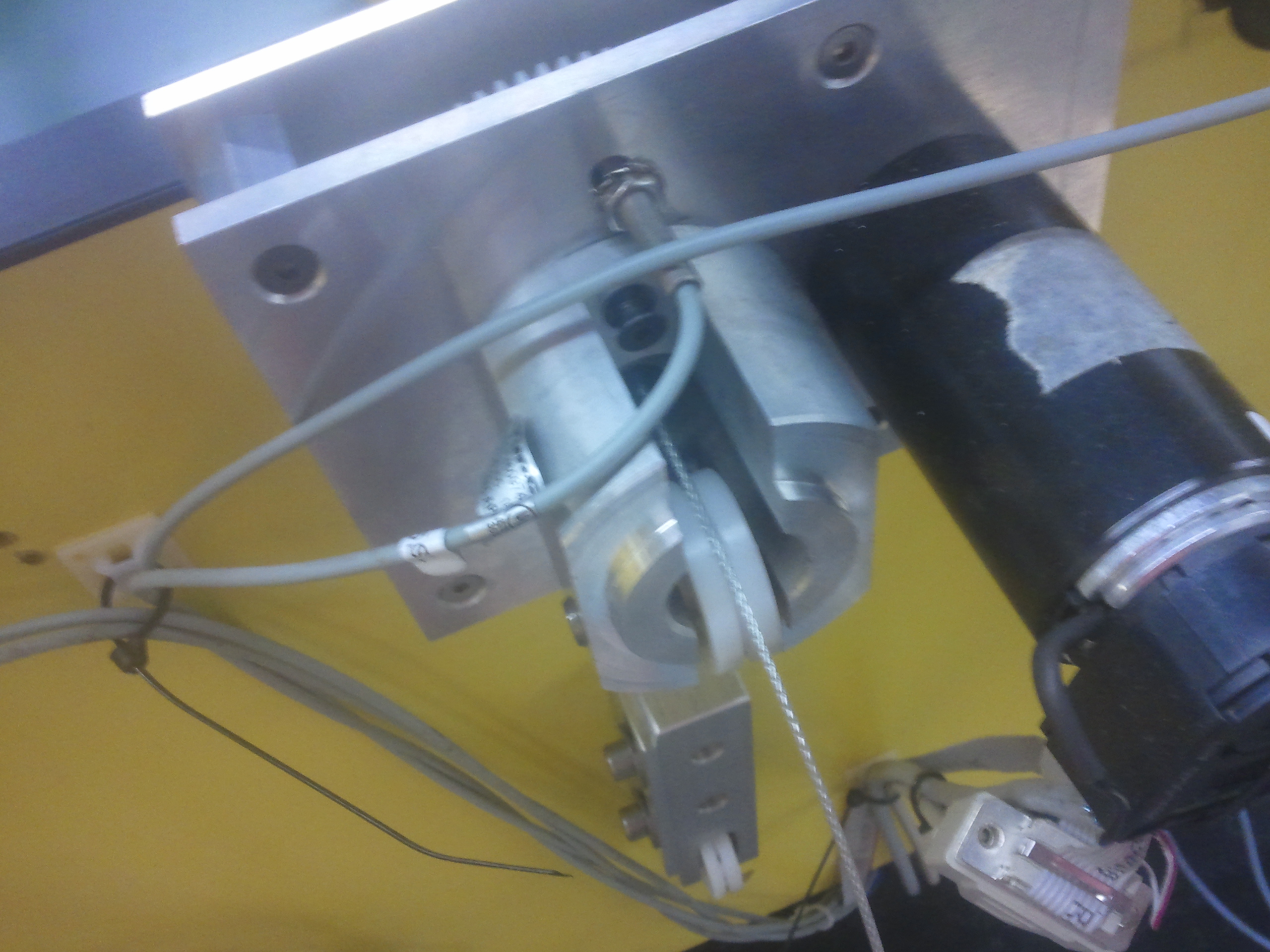
Attach pulley - Now put the cable tensioners in the highest position:

Adjust cable tensioner - Next feed the cable towards the pulley underneath the cable via the correct route, and insert into the bottom pulley:
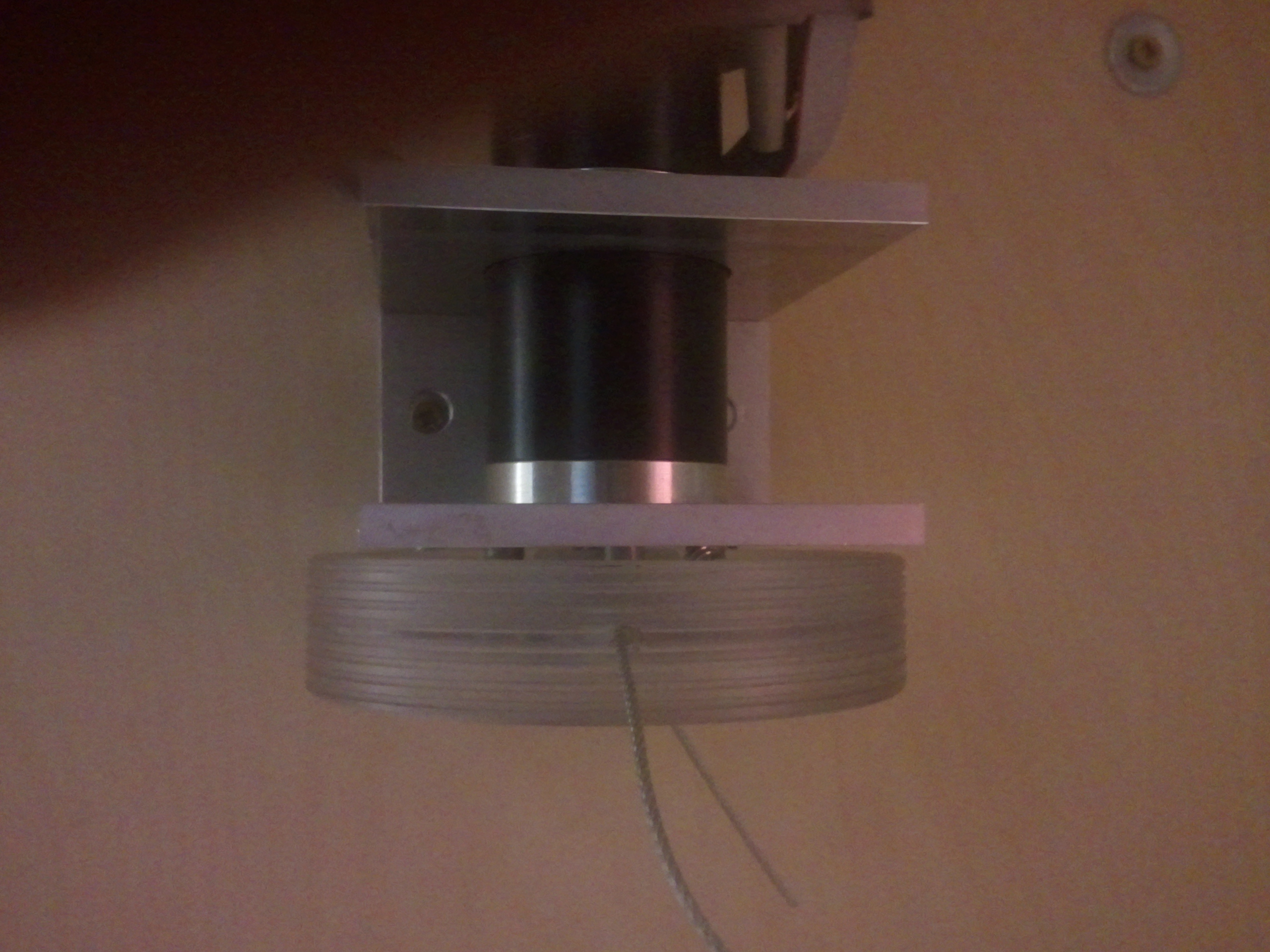
Insert the wire - I recommend inserting both cables first, as it can become quite fiddly otherwise
- Pull the puppets all the way to one side, then attach that side to the pulley leaving some room for movement
- The motor should be capable of pulling the puppets against the side
- I recommend starting this with the side removed furthest from the actuator (the actuators are not always centered underneath the table, so pick the `longest' side, which requires longest cable)
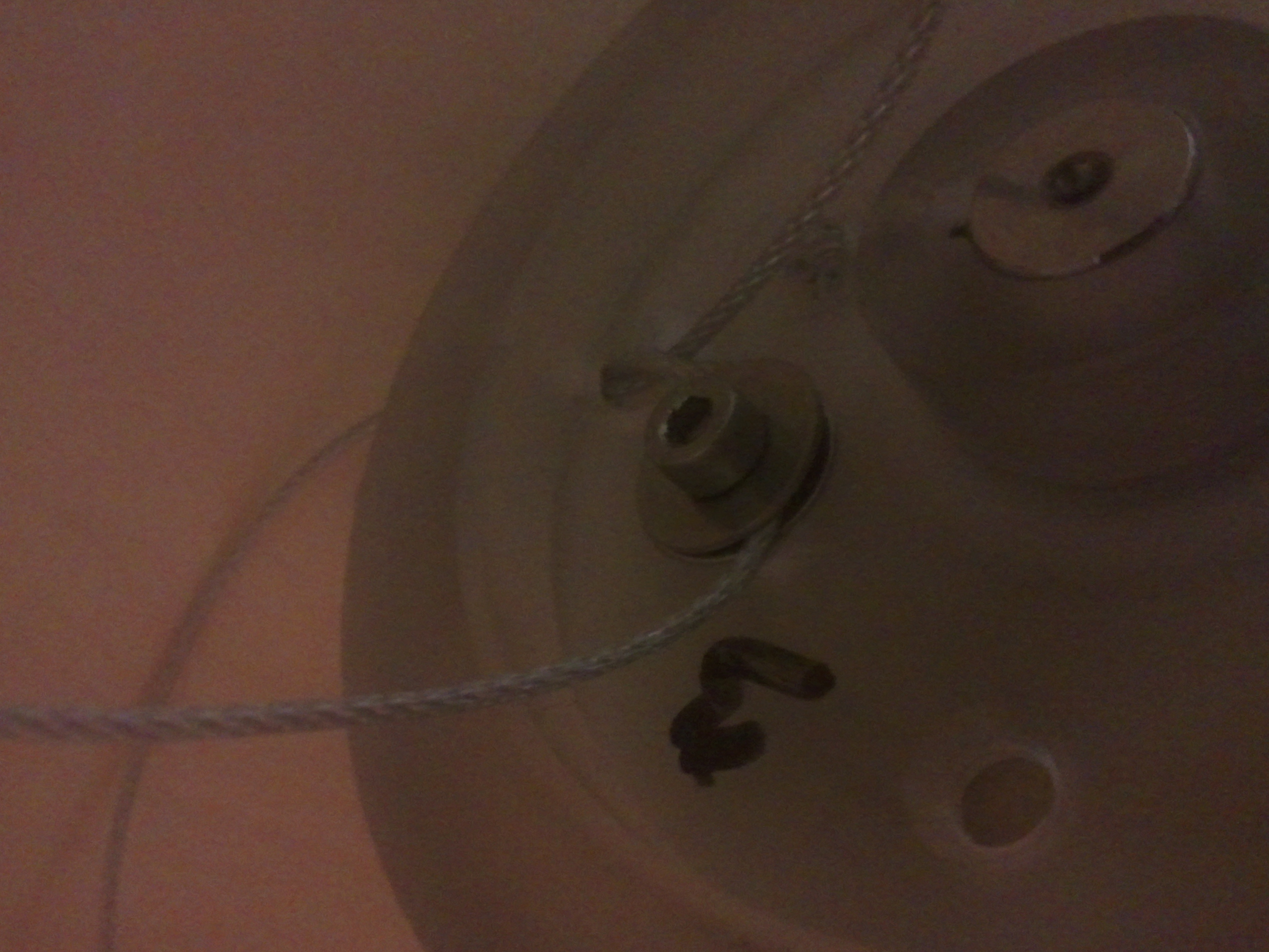
Attach the cable to the pulley - Make sure to seat the cable on the pulleys on this side of the table
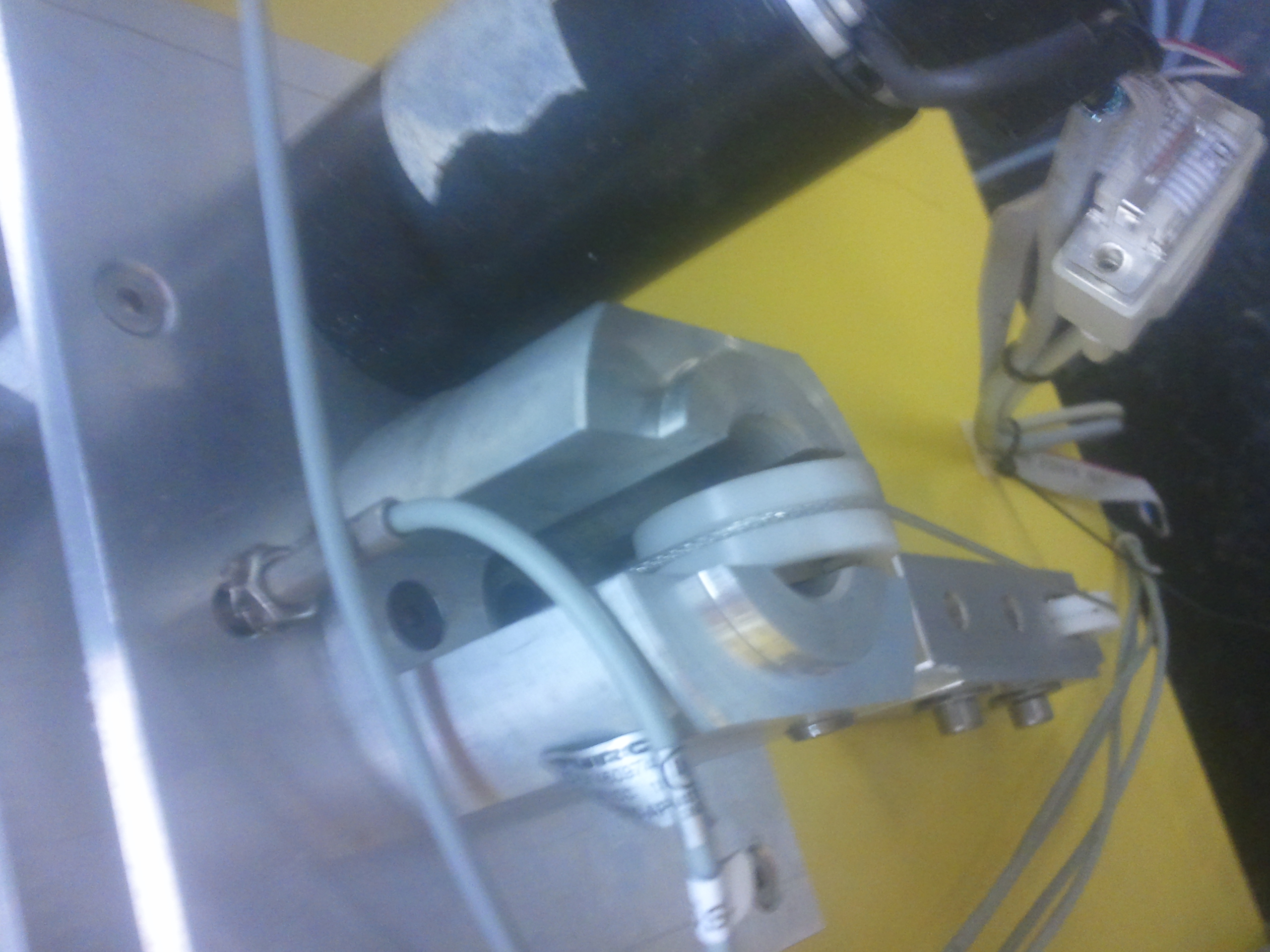
Check if the cable is seated like this - Now, slowly start rotating the pulley/motor, moving the puppets to the other side, rolling up the wire you already connected. You should provide resistances using the other side of the cable. It should now look something like this:
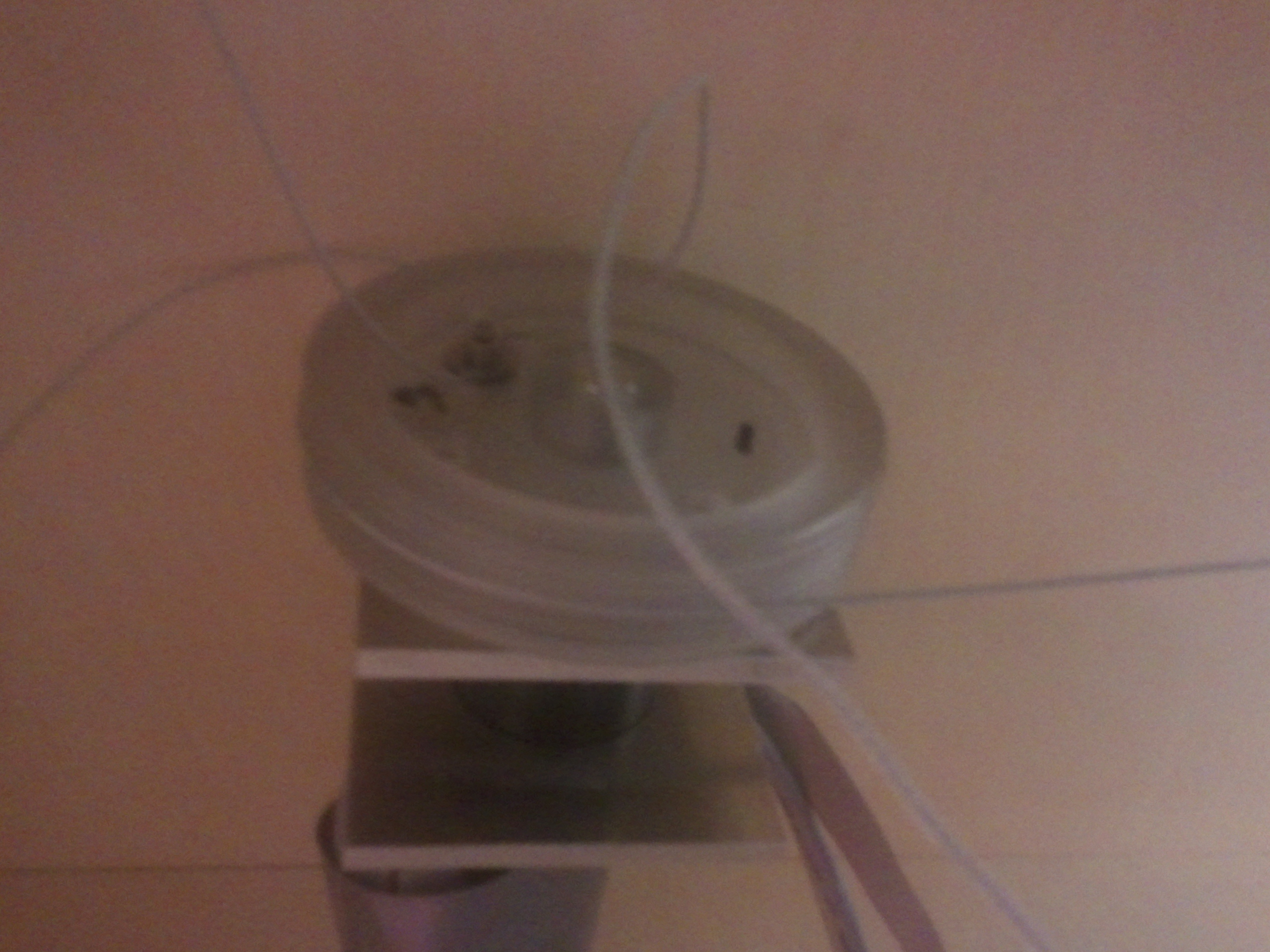
One side is rolled up - Make sure the other side of the cable is seated on the pulleys
- Now attach the second cable (make sure to keep the puppets against the other wall now), again trying leaving some room for movement.
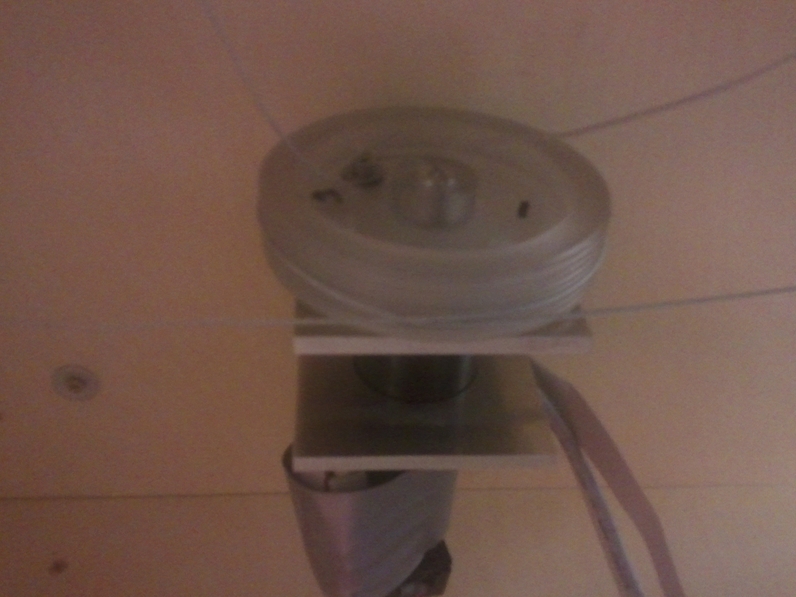
Attach the other side - Cut off any excess wire (not too much)
- Tighten the cable tensioner and you are done!
Other maintenance
For other mechanical maintenance you should request the help of Pieter in the DCT-workshop, be sure to do this well in advance as he can be quite busy/hard to reach.
For maintenance of an more electrical/mechatronics nature, it is best to approach Harry van der Loo, some work will have to be done by the GTD.
Ordering new parts
For mechanical parts (so not e.g. balls), mostly Pieter will order them himself as he also does the maintenance. If you require new cables you can should also requist him to order new ones, it always comes in handy if you bring a cable as an example (or measurements). It is important to note that the current cables are on the short side, so it is wise to order cables ~0.25 meters longer than the current ones.