Embedded Motion Control 2019 Group 9
Group members
Nicole Huizing | 0859610
Janick Janssen | 0756364
Merijn Veerbeek | 0865670
Design Documents
The Initial Design document can be found here: File:Initial Design Group9.pdf
The powerpoint presentation about the design is in this file: File:Presentation initial design.pdf
The powerpoint presentation about the final design can be found here: File:Presentation final design group9.pdf
Logbook
The composition of group 9 has changed twice. At first, George Maleas decided to quit the course at the 13th of May, two days before the escape room competition. At second, Merijn F. also quit the course on the 3rd of June. The motive for both students was that they lacked the c++ programming skills to meaningfully contribute to the project. Participating in the course would take a too large investment of their time. The code for the final challenge was written by Janick Janssen, Merijn Veerbeek and Nicole Huizing.
Initial design
Requirements and specifications
The following table outlines the requirements set by the hospital challenge, a well as the methods used to meet them.
For the escaperoom challenge these already held too, with the exceptions for the proper termination and finish time requirements. There PICO should properly stop after the finish line and the task should be completed within 5 minutes.
| Requirements | Specifications | |
|---|---|---|
| Operate autonomously | Read in prior given map
Obtain data through LRF and odometry, operate with SLAM and path finder | |
| Visit cabinets in order given at challenge | Executable takes in desired cabinet order | |
| Indicate task progress | "Speak" on arrival at cabinet
Take snapshot of cabinet | |
| Avoid deadlocks (30 seconds) or infinite executions | Have PICO recognize these situations and return to an earlier/random point before continuing to the task | |
| Obey speed limit | Ensure rotational speed is limited to 1.2 rad/s, translational velocity to 0.5 m/s | |
| Finish within 10 minutes | Limit the computational expense of the code
Ensure smooth movement | |
| Prevent collision | Keep a safe distance from walls and objects | |
| Proper termination | Stop after having performed interactions at the final cabinet | |
| Additionally, identify (moving) objects | Track unexpected points, add to map for statics temporarily for moving |
Functions
The following functions are used to complete the challenges:
- General
- Track system state
- Avoid collisions
- Plan local path
- Drive
- Hospital challenge
- Read and store given json map
- Determine cabinet order
- Identify wall segments and corners
- Localization
- Identify static objects
- Identify dynamic objects
- Update map
- Plan global path
- Take cabinet snapshot
- Audio comment on task progress
- Escaperoom
- Wall follow algorhithm
- Direct exit finder
Components
The used robot is PICO, the following components are part of, or used to interact with, it:
- Actuators:
- Holonomic base with three omni-wheels, that enables the translational and rotational movement of PICO
- Sensors:
- Laser range finder (LRF): Detects the distance and the direction of objects in the surrounding environment of PICO. It has a range of vision of roughly 230° functioning for objects at distances between 0.1 and 10 m.
- Wheel encoders: Together with the control effort they allow the determination of the robot’s position and orientation, taking into account possible inaccuracies due to error accumulation.
- Interaction
- Screen: a screen on PICO's "head" can be used as display for the running code (for instance while using opencv)
- Speaker: PICO can produce sounds of choice
- Computer
- Ubuntu 16.04
Interfaces
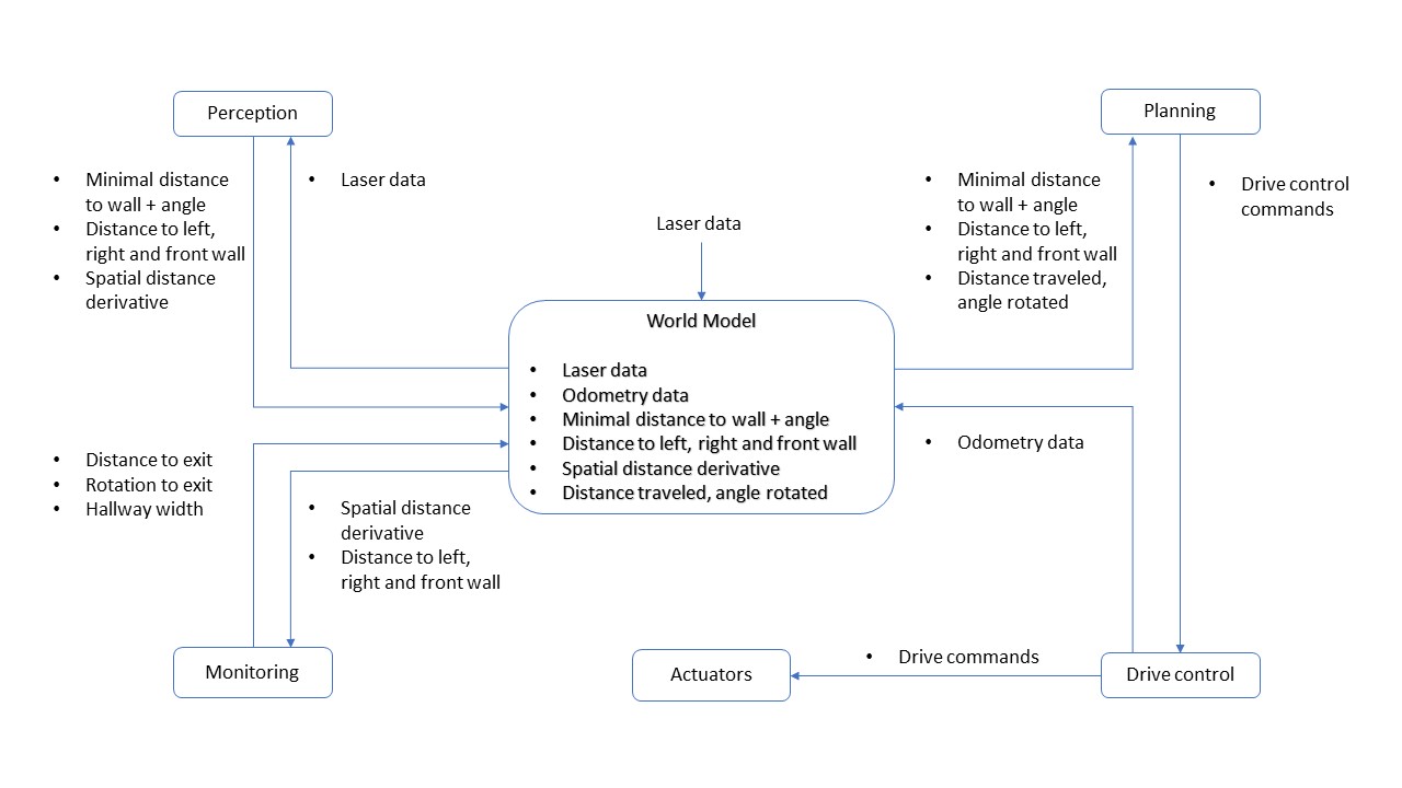
In the figure below you can find a schematic representation of the interfaces that we used. The concept is that the Worldmodel contains all the information about the world and PICO. All modules cannot communicate directly to eachother, but must communicate through the worldmodel.
Escape room challenge
For this assignment, we decided to work out two different strategies. The first one is the wall following strategy and the second one is the direct exit detection strategy. The idea was that the detection, drive control and world model code could be shared between both strategies and that only the planning module would be different. Pico should first try to use the direct exit detection strategy. If he fails to find the exit, Pico should change to wall following strategy. Since the direct exit detection code was not yet robust enough during the escape room competition, the code that was used in the challenge uses only the wall following module.
The table below presents an overview of the most important functionalities that Pico should have to compete in the Escape room competition.
| Wall following | Direct exit detection | Both |
|---|---|---|
| Rotate until aligned to right wall | Detect convex corners when seeing both walls | Walk through the hallway |
| Walk while staying aligned to right wall | Detect convex corner when seeing only one wall | Cope with wall misalignment |
| Detect exit from laser data on right side | Rotate and move to exit entrance point | Stop after reaching exit |
| Rotate to exit entrance | Prevent bumps at all times | |
| Cope with odometry deviations caused by slip |
Code architecture
For better overview and easier maintenance, the code is split up. The devision of the code resembles the interface model. The functionality of each module is coded into its own files. The modules can communicate with eachother through the worldmodel. This is made available in 2 ways. The first is that each module has its own class, which is stored in the worldmodel. Via the worldmodel, the class object can be accessed. The class has its own functions to set and get data. The second method is that important variables/objects are copied to the worldmodel. This way the objects can be access directly, instead of heaving access the class first.
There is a main file, which initializes PICO and the module classes. The finite state machine (used for planning) is also handled in the main file. The state of the FSM is stored both in this file and in the worldmodel. The drive FSM is also handled in the main file.
World Model
The class 'WorldModel' functions as main storage place for important variables that can be used by all other modules. To enhance separation of tasks among the different modules, all values stored in the World Model are private. The class also has some public functions by which other modules can obtain and process data.
The most important variables in the World Model will be explained here. The first one is the minimum distance to a wall, accompanied by the angle where it is found, relative to Pico. These values are used to allign Pico to the right wall and turn left in a corner. When the shortest distance to a wall is found on the right of Pico, he can walk straight ahead. However, if the angle is outside the margins, Pico will rotate either clockwise or anticlockwise until he is aligned to the wall again. If the shortest distance is found in front of pico, he will turn left until the closest wall is found on the right again.
The other important data structure in the World Model is a matrix, in which the spatial derivatives are saved. By spatial derivative, we mean the difference between the measured laser distance of one array and the next evaluated array. Between these two arrays, 4 arrays are skipped.
Detection
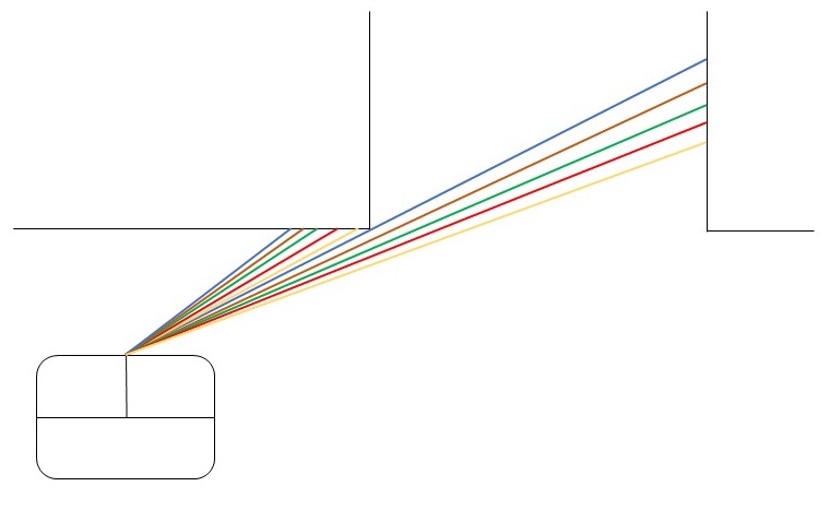
The laser data is called in the World Model and sent to the class 'Perception'. In this class, the laser data is converted to important variables as the minimal distance to a wall, the accompanying angle relative to Pico and the spatial derivative matrix. These values are then updated in the World Model.
In the class 'Monitoring', the output of the class 'Perception' is converted to useful information about the exit. There are two ways of detecting the exit. It depends on Pico's initial position which way should be used. If Pico is standing within the area extended from the two corners of the exit, Pico will see both walls of each convex corner. If Pico is located outside this area, it will only perceive one wall belonging to the closest convex corner and both walls of the furthest convex corner. For both situations, the matrix with spatial derivatives can be used.
First, there will be sought for a "gap" in the spatial derivative data. If the difference between the laser distance of one array and the array 4 steps further is above a certain threshold value, the angle of the first array is saved. This evaluation will be done for all arrays. By leaving 4 arrays in between, a real convex corner will have a higher occurrence than a small slit in the wall. A cluster of laser arrays with a high occurrence is expected to be the closest convex corner. In the figure on the right, the color combinations of laser arrays will give a high spatial difference. This cluster of arrays will be recognized as a convex corner.
Next, the spatial derivative matrix will be scanned for transitions from negative derivatives to positive derivatives. In this way, the furthest convex corner can be found (or both convex corners if Pico is between the corners).
The sideways, forward and rotational motions Pico needs to make to get to the entrance of the hallway are calculated. These values are stored in the World Model.
Planning
The global planning is defined in- and executed by the main program. To this end, a finite state machine is used. Pico starts by initializing all classes and sensors. If Pico is too close to a wall, he drives away from it. Next, it enters the 'direct exit finding' planning. It tries to localize an exit from its current position. If Pico fails to find an exit, he will turn around 180 degrees and try again. In this way, Pico should have observed every angle of the room. If Pico finds the exit, it will move toward the entrance, following the drive commands that were determined in the 'Monitoring' module. To account for slip, this procedure of localizing the exit and driving towards it will be repeated until Pico is close enough to the hallway entrance point. Now, Pico drives straight ahead and enters the state 'hallwayFollow'. In this state, Pico drives forward if it is not too close to a wall on both sides. He moves right if he is too close to a wall on the left side and moves left if he is too close to a wall on the right side. This procedure continues until Pico does not perceive a wall on the left and right side anymore. Pico stops and shuts down the program.
If still no exit is found after rotating, Pico switches to the 'Wall following' planning. Pico walks straight ahead until it finds a wall. He turns left until he is aligned to the wall and follows the walls, driving counterclockwise to the exit. If a large transition of the laser distance on the right of Pico occurs, Pico turns clockwise and moves sideways until it is standing in front of the hallway. Now Pico drives forward and enters the state 'hallwayFollow', which it only leaves when no walls on the side are detected and Pico has crossed the finish line.
Controller
The module 'driveControl' consists of a collection of functions. These functions are driveForward, driveBackwards, driveLeft, driveRight, rotateLeft, rotateRight and stop. Rotational and translational speed are fixed values that are stored in a configuration file. Each function updates the odometry data to keep track of the drive effort.
Wall follower
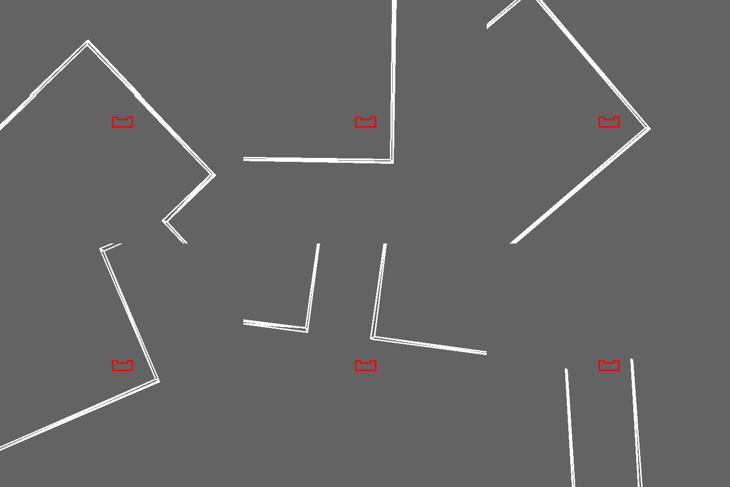
In the movie on the left, one can see a simulation where only the wall following strategy is used. As you can see in the movie, Pico walks to the wall and enters the wall-following module in which it adjusts itself when its angle with the right wall exceeds a threshold value. When he detects the gap at the right side, it turns towards the exit and enters the hallwayFollow module.
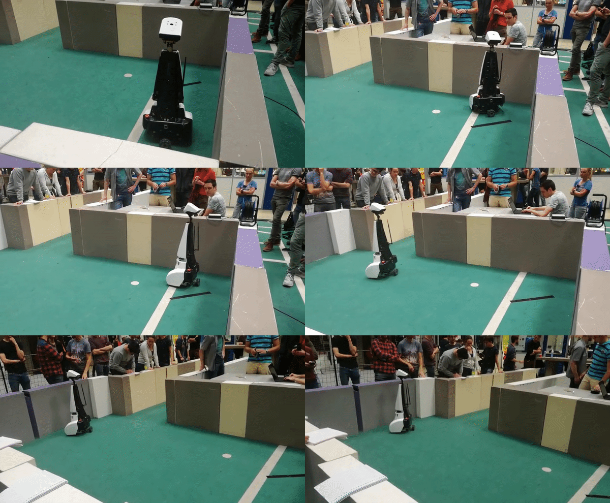
In the movie on the right, the real test-results are shown. The behavior of Pico differs from the simulated situation in two facets. At first, Pico tends to rotate too far, building up an angle with the right wall. It does not rotate to compensate for this. This lack of reaction is caused by choosing too high safety margins. At second, Pico does not turn towards the exit. Later, we found out that this was due to a missing absolute value in the calculation of the difference between laser range values on the right side of Pico. In the simulation, the gap on the right side gives very low laser range values, while in reality the gap gives relatively high laser range values with respect to the wall Pico is following. By taking the absolute value, this problem would have been addressed.
Reflection
Both previously mentioned points could have been remedied if we would have used the test sessions more efficiently. The full code was not finished yet when we had the last test session before the challenge. We could better have focused on either the wall following strategy or the direct exit finding strategy. By choosing to do both, we got our self into time problems.
The code itself features all modules that the code should have. However, in the communication between the modules, some improvements can be made. The code would have been more readable if we would have used flags to control the state of the state machine. Now we send a lot of data from the world model to the state machine to assess whether a state should be left and a new state should be entered. Also, we could have sent the state of the state machine to the world model and connect with the drive control from the world model. At last, the code for exit detection was written too much in a sense-plan-act manner. This method is prone to failure, especially when data is inaccurate.
Exitfinder
The exit finder functionality was intended to more quickly reach the exit by scanning the room, and then moving to the exit in one straight line.
For this method four scenarios are possible:
1. PICO is not in front of the exit: it can be detected by spotting a large jump in distance between neighboring LRF angles.
2. If PICO is in front of the exit: possibly some very large ranges (larger than room dimensions) can observed when looking through the hallway. Alternatively, the sign of the derivative of range to it's angle can show the exit location.
3.An exit has not been detected, PICO will move away from the closest wall and attempts the previous again.
4.If after 3 still no exit has been found PICO will initiate the wall-following method.
Points 1 and 2 are performed simultaneously while evaluating the LRF data, PICO turns around if no exit is found before continuing to point 3.
Though the method worked for simple situations problems were observed with slits in the wall, these would be incorrectly identified as exits. To overcome this instead points being a few angle steps apart were compared. For small slits only a few consecutive angles would show a large jump in range, for larger slits (exits) a large amount would show the jumps. However the presence of slits still caused problems. It is expected that this was caused by not properly taking care of the data at angles were nothing can be seen: at these points the observed range is very small (as opposed to the expected very large), causin unexpected behaviour.
Hospital challenge
World model
Similar to the worldmodel in Escape Room challenge, the worldmodel in the Hospital challenge contains the information about the world and PICO itself. The modules, which are described below in more detail, are saved in the worldmodel. This way, every function could obtain all information through the worldmodel if required. This is not needed in general, as the most important elements of the modules are stored as unique variables in the worldmodel for easier access. The worldmodel also contains various variables, such as the current location and orientation and the destination cabinet.
The worldmodel is set up in such a way that the communication between the modules goes through the worldmodel. Public functions have been added to the worldmodel, which allows the modules to change the stored variables in the worldmodel. In general, only one module is able to change a variable, but all modules can read the variables.
During initialization, a map will be created based on the provided json file. This map will contain a grid. This grid is in path planning. Each grid point has a variable to indicate it is accessible. The map and grid are used in path calculation. When a static object is observed, it is added to the map and the grid points the object is on are made unaccessible. This way the gridpoint below the object will not be considered in the new path planning. This map is stored in the worldmodel, so it can be accessed by all other functions through the worldmodel.
Perception
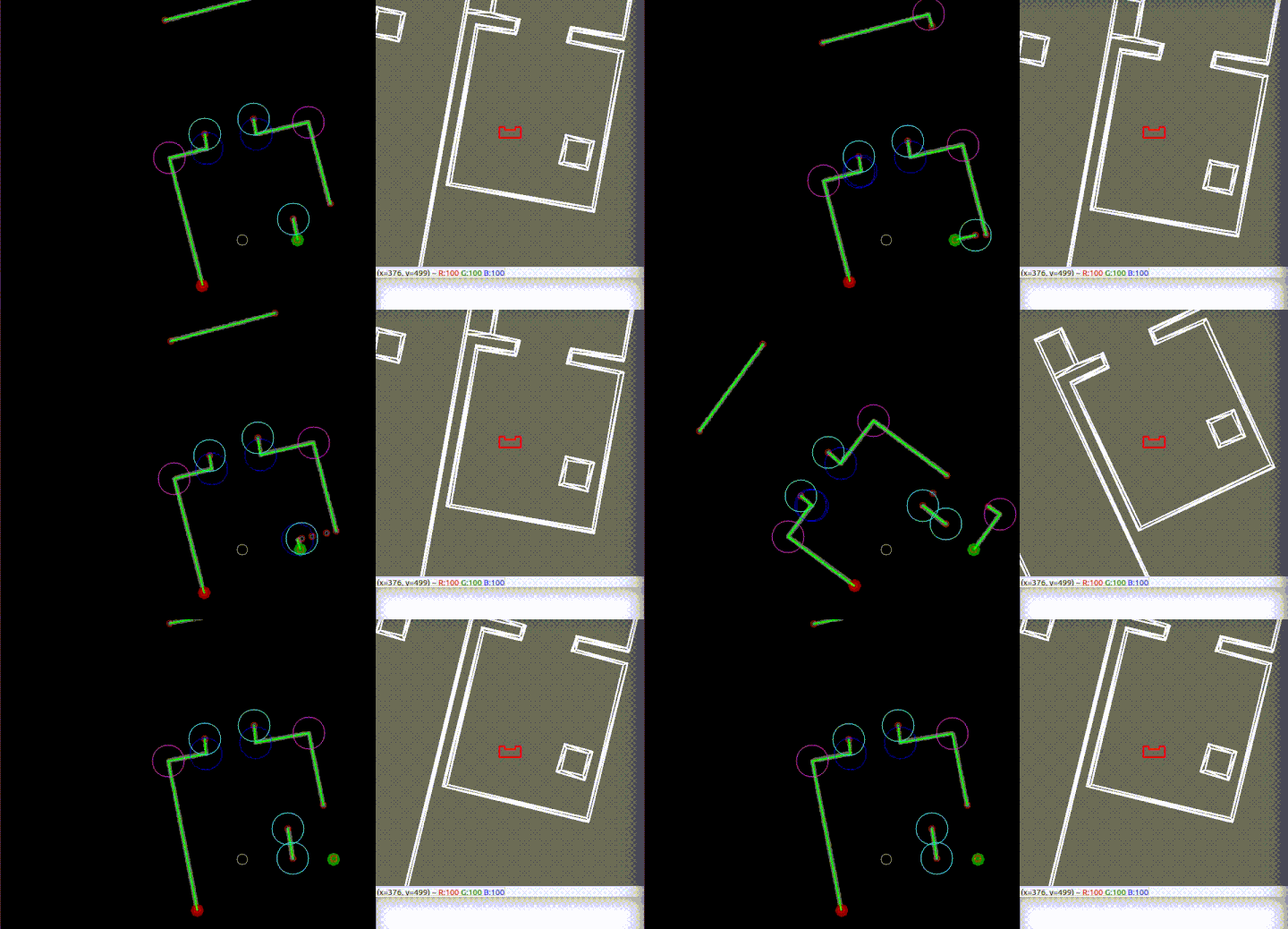
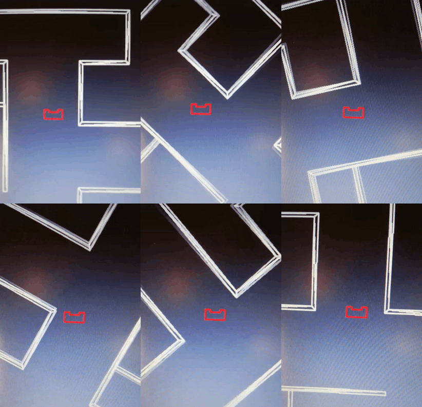
Through the LRF an array is received with the distance to observed points at increasing angles. It is analyzed so as to identify wall segments and corners. The different segments and corners are added as structs to lists that are used for localization, mapping and object detection/tracking.
It was found that data at the edges of PICO’s vision was unreliable, so a set number of datapoints there were thrown away. It was seen that these point were on a line from PICO towards the reliable data, checking which points lie on that line ensures not too much is lost. Also points with values outside of the LRF’s possible range are discarded. This way information on points very far away (>10m) is lost, but this was not considered a problem for the contained scenario of the hospital.
Next the “rupture points” are identified, these are the points which have a large distance to its neighboring points. The allowed distance for a neighbor is determined using an adaptive breakpoint detection, the used algorithm is as in this paper by Borges and Aldon. Rupture points with another on either side are observed on walls parallel to view lines. These could be used for detection of wall/objects but are deemed unreliable and could hide features, so they are not further used. If the begin and end points of the dataset were not already in, they are added to the rupture points. This is done so to properly identify the first and last segments in PICO’s field of view.
We can now check whether any rupture point is a “suspected corner”, these are corners that cannot be seen (only one wall forming the corner is observable), but are implied by the nature of the environment (only right angles). These points are neighbored on one side by another rupture which is at a distance further away from PICO. As these corners could never be concave (we’d be able to see both walls) we know them to be convex. Their angle and range as observed by PICO as well as their Cartesian coordinates in PICO’s frame are included in a new corner struct and added to the corner-list.
Also, now continuous sets of data have been found which represent objects or wall segments. Line segments are defined between subsequent even and odd rupture points. For each a struct is created with information on their begin and endpoint, which is then added to a segment-list. However, their shape still needs to be found. For this every segment is analyzed using iterative end point fitting (IEPF). In this a line is drawn between the extremes of the segment (first and last point in the set). For every of the set’s points the distance is calculated to this line. The point furthest away is identified as a corner and it is added to the corners list, as was done with the “suspected corners”. One addition is that these corners are not necessarily convex. Their type can be determined by comparing the distance of the corner to PICO to the distance of the corners neighbors to PICO; a convex corner will have the corner point nearer, a concave one may have one or both neighboring points closer to PICO.
Now the line segments are adjusted: the current segment is adjusted by setting a new endpoint as the position of the found corner and a new segment is created starting from this corner to the current endpoint. The new segment is added to the end of the list of segments. The adjusted current segment is then checked for possible additional corners before continuing to the next segment. If none are found the next segment in the list is evaluated.
The completed lists of corners and line segments can then be used by the localization and mapping functionalities. In both simulation and experiment it is observed that the features “jitter” around a few cm as could be expected from the uncertainty in the LRF data. This is taken into account by the function using this data, but the effect could possibly have been lessened by averaging/adjusting the extrema of the line segments. Also, on occasion inaccuracies in the measured ranges causes a corner to "flip" inside out, so that it temporarily changes from convex to concave or vice versa. As this is a very short lived process it is not observed to cause real trouble, but a more robust corner detection method might fix it altogether.
After localization the currently observed corners are translated to the map frame and matched with the corners that are expected to be seen. If a match is found the corner’s position is updated through averaging it’s coordinates between old and new, taking into account the number of times it has been observed (upto a maximum number). If the corner has not yet been seen it is added to a list containing points which form potential static/dynamic objects. They are not immediately trusted as they may be false positives. They are given a time since last seen, if subsequent measurements within a short timespan also find the same corner at this point it is considered to be part of a static object. The occupied points are then written to the grid map by setting the matching coordinate points to occupied.
Localization
In order to know in what direction PICO should go, it needs to know its current location. To achieve this, PICO has been given a localization module. This module makes use of Monte Carlo localization (MCL). The module tries to determine the location of PICO on a pre-known map of the surroundings. The current location is used to determine the path to the next destination and to make PICO follow that path.
The map the world isdivided into several grid points. The goal of the localization module is to determine on which gridpoint PICO is and with what orientation. It is not required to know the exact grid point, because the grid points are used for the global movement of PICO. To move PICO more precisely, for example when it needs to allign to a cabinet, PICO does not make use of the current grid point, but it alligns itself by the laser data.
The current grid point of PICO is determined in the following way. The initial starting area of the Hospital challenge is roughly known. This information is used to reduce the possible locations of PICO. The gridpoint in the middle of initial starting area is chosen to start the MCL. All grid points within a certain distance of this gridpoint is added to a list. The gridpoints in this list cover all possible starting positions in the initial staring area. Multiple particles are created for each grid point in the list, each with a different orientation. The MCL module must try to find which particle has the most likely location and orientation of PICO.
When PICO has moved, the current location can be estimated based on the old known location and the odometry data. This gives a starting grid point and orientation to create the particles. Because the rough orientation is known, the number of particles can be reduced, because the likelyness of certain grid points and orientations are very low. For example, if it is known that PICO is facing north and it has turned about 5 degrees according to the odometry, it has no use evaluating particles facing south. It is only required to check particles which have an orientation of 5 degrees of the north, but a larger range is used to make sure that the particles with the correct location and orientation is in the list of particles.
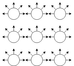
The image below is a small example of how the particles are created. In this example, there are 9 grid points. Each grid point has different 5 orientations. That means that there are 45 particles in this example. The real implementation uses a grid of 1 squared meter with grid points space 10 cm apart from eachother. The orientation of the particles have a range between 45 degrees clockwise and 45 degrees anticlockwise of the orientation of PICO, with a stepsize of 1 degree.
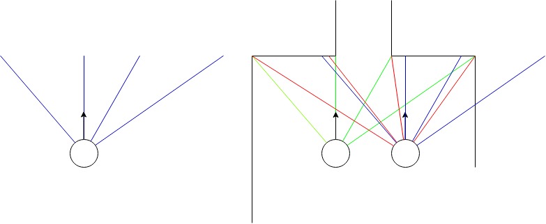
The localization module calculates the probability of the correct location and orientation for each particle. It uses corners to calculate the probability. With the worldmap, the angle between the corner and the orientation of the particle can be calculated. The same holds true for the distance to that corner. This is compared to the laserdata. In the perception module, a list of all currently visible corners is created. Each corner element in that list contains the angle of the laserbeam and the distance that beam measuresed. Each corner of the model is compared to all corners of the laserdata and the corner from the laserdata with the best match is taken. This way, a list of matching corners is created. The angles and distances of the model corner and and the ones of its matching laserdata corner are put into a Gaussian function. If the particles is close to the location and orientation of PICO, the angles and distances of the model corner and its matching corner are very similar, resulting in a high probabilty. If the particles location and orientation is a bit off, the list of matching laserdata corners will be the same. However the distances and angles have a slightly bigger difference, resulting in a lower probability. It is possible that a wrong laserdata corner matches well with a model corner and results in a high probability. However, this will make it likely that the other corners do not match well and the overall probability will be lower.
The image below shows an example of a MCL calculation. Assume that the perception modules sees corners at the and of the blue lines of the left image. From the worldmap, it can be determined that the left particle of the right image sees corners at the end of the green lines. If this is compared to the cornes from the perception module, the angles and distances of the corners match nicely, resulting in a high probability. Now consider the right particle of the right image. From the model the corners are determined to be at the end of the red lines. From the laserdata, PICO has determined that the corners should be at the end of the blue lines. It can be seen clearly that the red and blue lines have a different angles and distances. From this it can be concluded that the probability that the left particle represents the location of PICO much better than the right particle.
The implementation of the Monte Carlo Localization is based on this project by this project of Dr. Rainer Hessner.
Path planning
Global path planning
The hospital is divided in structs 'room'. This is done both to preserve the semantics and for practical purposes: it reduces computation time for local path planning and it makes it easy to call information about corners and cabinets in the proximity of Pico. A 'door' is a separate struct. The connections between all rooms and doors are stored in a graph. A vector 'globalPath' is filled by repeatedly choosing the connected door/room with the highest ID-number (if there are more possibilities). ID's that are already in the path are ignored to prevent Pico from walking in a loop. When a doorway is blocked, the connection will be removed from the graph. The route calculated in this way is not per definition the fastest route, but this is not needed to succeed in the challenge.
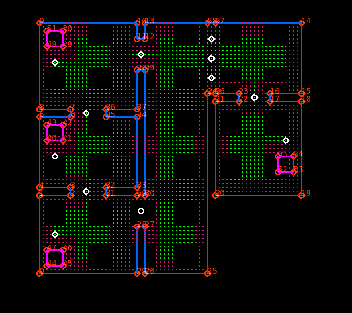
Each cabinet and each door have a unique enter-gridpoint. These points are used for local path planning. As the "large door" connecting the two parts of the hallway could be partly obstructed, three enterpoints are assigned to this door. If no obstruction is present, the middle node will be used. The enterpoints can be viewed as white circles in the image left below.
Local path planning
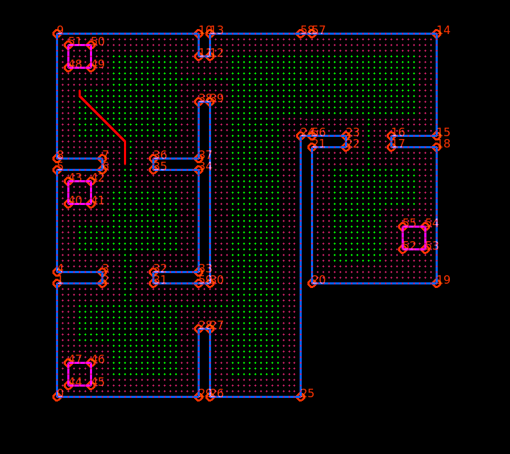
To plan Pico's path between enter-gridpoints, use is made of an A* pathplanning algorithm. This method was chosen over Dijkstra's method because it is faster. We will choose a heuristic function that is admissible, so it will be guarenteed that A* will give the shortest path from start to end.
All grid points on the map come with a boolean "accessible". Points that are close to a wall or an object receive the value 'false'. Mapping new objects is also based on this principle: whenever a new static object is detected, the gridpoints it covers will become unaccessible.
After the A* function is called with a certain start-gridpoint and end-gridpoint, it first goes through some checks. These checks assess whether the startposition and endposition are accessible and whether the startposition is the destination itself. If the startposition is unaccessible, the gridpoint itself and the points directly around it are temporarily made accessible (this is needed when Pico accidentally got too close to a wall or object).
Next, the start-node is put in the open list. At every cycle of the loop, the node in open list with the smallest f-value is evaluated. The f-value of node n is the sum of the cost of the path from start to node n and the heuristic cost of that node. This current node is put in the closed list. Next, the eight nodes around it are evaluated. If one of the nodes is the destination, the path from start-node to destination-node is reconstructed. If not, the cost-functions of these nodes are updated and if they are not yet in the closed list, they will be added to the open list from which the node with the lowest f-value will be evaluated in the next loop.
Finite state machine
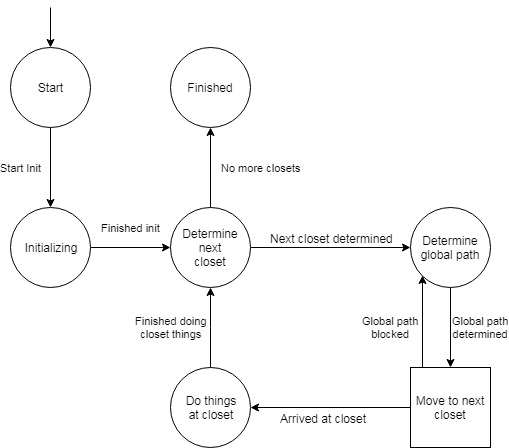
To determine which actions PICO should execute, a finite state machine (FSM) is implemented. The finite state machine is divided into 2 part: the main FSM and the drive FSM. The drive FSM is actually a sub-part of the main FSM, but it is split for a better overview and easier maintenance of the code.
The main FSM controls the global planning of PICO. The initial state of the main FSM is the initialization state. In this state, the world model and all other modules, like the perception module, are initiated. The json file is read and from this data a map of the world is constructed. The localization module determines the initial position and orientation. Once everything is initialized, the FSM switches to the next state. In this state the next cabinet that has to be visited will be determined. This cabinet object will be stored in the worldmodel. Once the next cabinet is determined and set, the FSM switches to the path planning module. In this state, it will determine which rooms PICO has to visit and in what order. This global path is saved to the worldmodel. When the global path is determined, the FSM will switch to the driving state, which is described in more detail below. Once PICO arrives at the cabinet, it switches to the next state. In this state PICO will take a snapshot of the laser data and saves the snapshot. Then it will switch back to the state in which it determined the next cabinet and the loop starts again. If PICO has handled all cabinets, it will switch to the finish state and can be shut down.
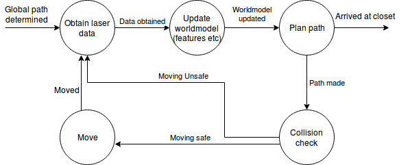
When PICO has determined the next destination, the main FSM switches to the driving state. In the driving state, the states of the drive FSM are "activated". (The main FSM actually switches to the "initial" state of the drive FSM) The drive FSM is a continuous loop of different processes. The first process in the loop is obtaining laser data. After the data is obtained, the worldmodel is updated. The perception module takes the laser data and updates the map and various other variables and saves them to the worldmodel. Once the worldmodel is updated, PICO switches to a new state. In this state, PICO first determines if the destination is reached, based on the updated worldmodel. If this is the case, the drive FSM will be "disabled" by the main FSM switching to the next state. If the destination is not reached yet PICO will determine the local path to the next destination of the global path. First PICO evaluates if the old planned path is still viable. If this is the case, it will continue following that path. This will save compuation time. If the old path is not vialbe anymore PICO will calculate a new path. With a viable path is available, PICO first does an additional check to check if the next move action is safe. The additional check is added because an object could have moved on the new path during the path calculation since the last time PICO obtained laser data, although this situation is very unlikely because time between obtaining the laser data and finishing the recalculation of the path is small) If the path is safe, PICO will move a step and then it will start the loop again. If the path is not safe, PICO will not move and will start the loop again.
The drive FSM will first try to find a path to the next destination of the global path. If it is not possible to create a path, because the path is blocked by a closed door for example, the main FSM will switch back to the global path planning state. Then it will create a new global path while not using the blocked points.
Results
The video below shows the performance of Pico in the final challenge. We have to say that this is not exactly the result we hoped for. As can be seen, Pico has difficulties finding the entrance of the first room. This problem is due to an unfixed bug in Pico's localization. Pico manages to determine it's global route to cabinet 0. He starts it's local route to it's first destination: the doorway of the first room. However, he turns a bit too far and heads to the corner of the doorway. Pico is programmed to step back when he is too close to a wall. After reaching a certain backward distance, Pico relocalizes itself and recalculates a path to it's destination. However, due to the problem in localization, he thinks he is outside the zone where he expects himself to be. He now re-takes the old route until he gets too close to the wall again and stays in this loop forever.

Discussion
A solution to the SLAM problem using Monte Carlo particle filter in combination with A* path-finding has been created as a method to complete the hospital challenge. Although the group feels that the final product was close to being able to handle the hospital challenge, the set requirements could not be met. The decreasing group size during the project caused problems not only due to the increased workload on individual group members. Two side effects were difficulty due to not being able to focus much on particular parts of work and secondly dependent code not being delivered as expected causing development backlogs. It seems that these may have been prevented (at least partly) with a more rigorous planning at the start of the course. This may also have helped in getting more out of the testing moments. Additional time could have been saved by investing more time at the start to get familiar with tools such as git. In particular it seemed that the development of the localization code has been left out too long. Although in the end it seemed close to work properly (only angle offsets, and only after movement) in hindsight it might have been a good idea to, when time became pressing, develop a more simple solution (for instance based on the wallfollow method). Further development would have to first solve this problem. Next the functioning of the object detection should be checked, and a computationally cheaper alternative to the grid based A* algorithm may be developed.
Code
The main pieces of work are in the path planning, feature detection and particle filter. The main parts of the code can be found in the following snippets:
Link to code for aStar path planning: https://gitlab.tue.nl/EMC2019/group9/snippets/132
Link to code for feature detection: https://gitlab.tue.nl/EMC2019/group9/snippets/161
Link to code for Monte Carlo particle filter: https://gitlab.tue.nl/EMC2019/group9/snippets/154