Embedded Motion Control 2015 Group 1 - Week 5
Maze mapping initial approach
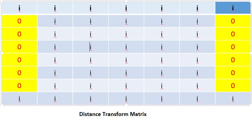
Mapping the maze was an initial problem where the team decided to use different approach for mapping. After a long research and analysis using journals and websites that focuses on the LFR Mapping strategy, one of the team representative came up with the idea using SLAM (Simultaneous Localization and Mapping). It is a very popular method used to map the path of the LFR without using other sensor that has an high error rte. Its very robust and the signal to noise ratio is very high. So the error obtained can be minimized using filters. This method is very accurate compared to the odometer data. The LFR scans the area in a 2D plne. The local swept area is converted into a grid map that is represented by a DT (Distance Transform) Matrix. This is done using the LFR that considers the point where it meets the wall or an object as a value equivalent to '0'and, the other parts are considered as infinity and the values are stored in a matrix.

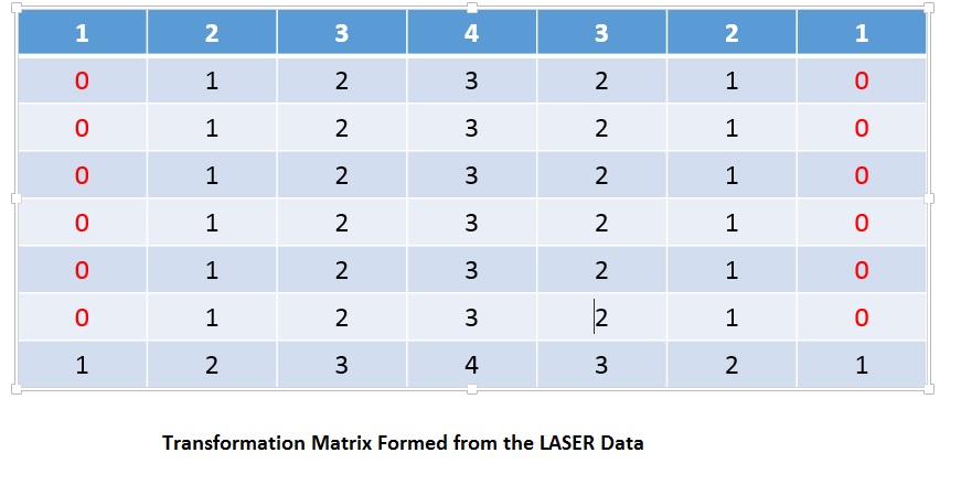
At the higher level the laser assigns distances from the wall to the LFR source with numbers to each position corresponding in a matrix using the function DT Matrix into T(X,Y,Φ) by linear simplex method.The DT matrix provides the information of each grid of a matrix with the Euclidean Distance to the nearest obstacle using the function DT(x,y)= min[(x-i)^2+(y-j)^2 => i=1, ……,M, J=1,…….,N]. M,N are the size of the matrix ( depends on the size of the path).

The Dt is transformed to x,y form of transformed matrix. Using the transfer function coding in C++ it is possible to convert the matrix in to coordinates.With the coordinates obtained it is easy to set the target in the half the range from it using the distance formula. then the PICO moves to that coordinate and the same process is done from that coordinate. The process is continuously repeated where the area scanned is mapped and stored in a stacked array. The turnings which is addressed by NODE in a junction is used to store the coordinate value using a seperate variable. This storage will enable the PICO to know the location of the turn and in case of loops it will enable it to know the coordinate where it was already there.
A simpler approach was also designed to make the decisions and keep the travk of the nodes named as the node approach was used, This is discussed in the section called as #Maze Mapping