Embedded Motion Control/Libraries
In this chapter the libraries processing of the vision information are described and needed for communication. The startup procedure of the earth computer is also included in this chapter.
Video processing on the earth station
To navigate through the unknown mars landscape, vision information plays an important role. By using vision information, the positions of the lakes are determined which are in the field of view. This information can be used as input to determine the trajectory of the mars-lander. Due to the limited onboard computational power of the Mars-lander, the main part of localizing the lakes is done by video processing on the earth-computer. The video processing is based on both color and dimensions of the lakes in the captured images. The centers of the lakes is determined in terms of pixels and linked to the sender which communicates with the Mars-rover. Fig. 5.1 roughly represents the structure of the image processing. Especially if unexpected output is given by the vision system, it can be useful to roughly understand the main steps of the vision module.

The main steps will be described shortly in the remainder of this section.
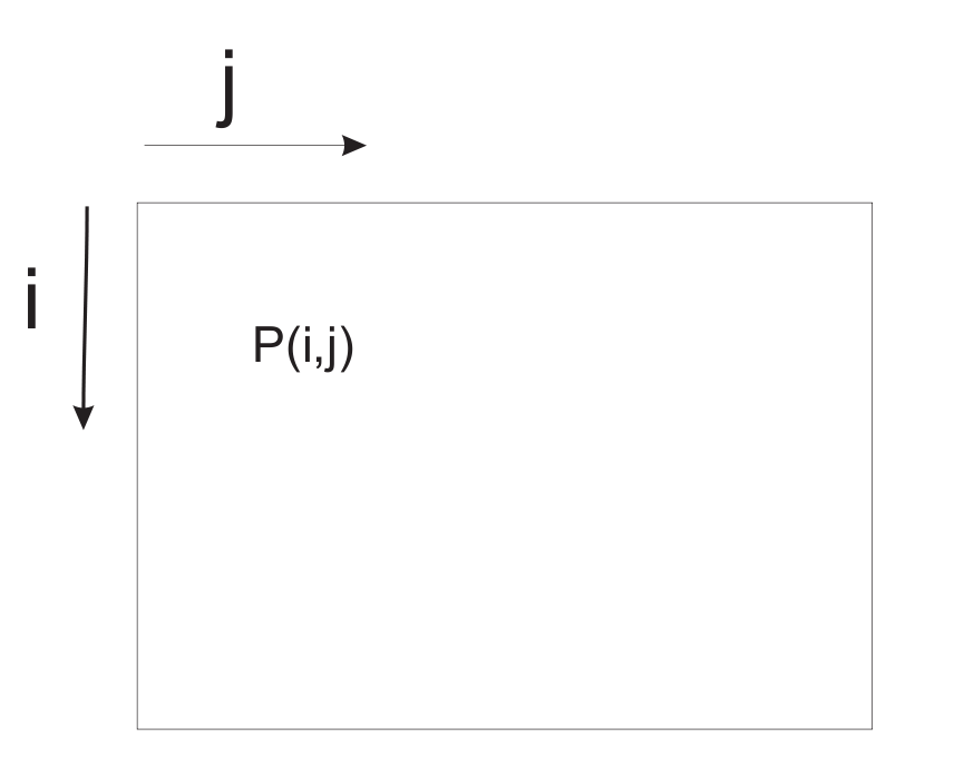
- Acquisition: The image is acquired by the standard acquisition block of Matlab which can run at several sample frequencies. The output of the camera is given as three matrices: Red, Green and Blue, where each matrix exists of 240 × 320 pixels. It has to be emphasized that the pixels are numbered starting in the left-upper corner as indicated in Fig. 5.2.
- Color segmentation: Due to the distinct colors of the mars landscape, the objects in the mars environment can be separated based on color information. Every pixel has three [R,G,B] color values between 0 and 255 (short int). This could be interpreted as a location in the 3-D RGB color space. By defining bounds in the color-space, one is able to test for a certain color. To be robust for lightning conditions, these bound are chosen rather loosely. One should keep in mind that all objects in the background which appear more or less blue could disturb the image processing as they may appear as possible lakes.

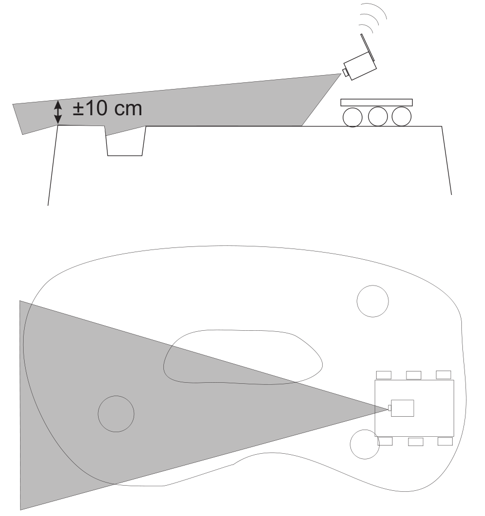
Figure 5.2: Definition of pixel numbering - Blob-analysis and selection: Blob-analysis is used to search for regions of dense blue pixels. The outer bounding box of the blobs and its center are given as output. Since a high number of candidate blobs can be given as output, also a geometric check is performed based on the relation between the height and the length of the blob in relation to the distance. This check is based on geometric relations where the dimensions of the lakes are transformed into a height and width in the image of the camera. The angle of the camera with respect to the ground is one of the key parameters in this relation. In order to perform well, the angle of the camera with respect to the ground should be set properly. Fig. 5.3 depicts how the angle of the camera should be set. The candidate blobs that fulfil the conditions are given as output for the positions of the lakes and are given to the infrared sender. The structure is as follows: [math]\displaystyle{ \begin{bmatrix} \text{row } i \text{ of first lake}, & \text{row } i \text{ of second lake}, & \text{row } i \text{ of third lake} \\ \text{column } j \text{ of first lake}, & \text{column } j \text{ of second lake}, & \text{column } j \text{ of third lake} \end{bmatrix}. }[/math]
- Most of the time only one lake is found, or two in rare cases. If the corresponding lake is not found, zero is given as output for the second and for the third lake respectively.
Starting the earth computer
The earth computer can be started in the following steps.
- Convince yourself from the fact that the camera is powered on and the camera receiver is connected to the pc.
- Start the program GrandTec Walkguard from the start menu. If the camera is connected properly, the camera image appears. Since the color segmentation proces depends heavily on the settings of the camera, these parameters have to be set. In the program GrandTec Walkguard, go to the Tab:
Video. Set the following values:- Brightness: 149
- Contrast: 174
- Saturation: 191
- Hue: 143
- Note that these values are a guideline. Since the values depend on lighting conditions some can deviate from these values. It is possible that the setting of the camera parameters has to be repeated if the camera has been disconnected from the power-plug.

Figure 5.3: Setting the angle of the camera
- In order to properly check the geometry of the lakes, the camera should have the right angle with respect to the underground (see Fig. 5.3). Adjust the angle of the camera according to this figure. Exit the program GrandTec Walkguard.
- Color calibration (not needed, or done by tutors).
- Start Matlab and go to the directory
D:\MC\vision. Open the Simulink model filecommunication_and_vision_with_viewers.mdl. In order to guarantee best performance, the priority of Matlab can be increased. Press:Ctrl+Alt+Del, go toTask Manager,processes, right-click matlab.exe. Go toSet Priorityand setReal-time. Note that several Simulink schemes are available. If problems occur which could be due to the vision processing: one could chose to run the program:vision_with_viewerto get
more info about the color-classification. Start the Simulink scheme.
Communication
LegOS Network Protocol (LNP), which is included in the BrickOS Kernel, allows for communication between BrickOS powered robots and host computers. The communication is realized by the infrared ports. Therefore, first of all make sure that there are no obstacles between two communicating RCX bricks to prevent communication errors. For the purpose of this course there have been made adjustments and modifications in order to make the communication between RCX bricks and between RCX bricks and the host computer a lot easier.

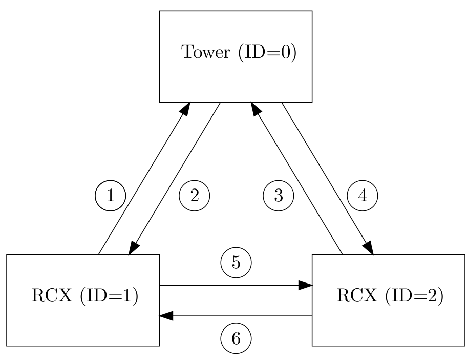
A possible configuration of a communication setup is depicted in Fig. 5.4. It contains two RCX bricks and one host computer equipped with the Lego USB Tower. Each client has its own iden- tification number. The host computer is identified by ID = 0. The two RCX bricks are identified by ID = 1 and ID = 2. In the main C-file this ID should be defined, for example
#define ID 1
for RCX brick one. Next, the C-file com.c should be included using
#include "com.c".
Make sure that you first define the ID before you include com.c. The C-file com.c is makes it possible to send and receive integers or arrays of integers. The main functions in this file are called com_send and read_from_ir. The source code of the C-file com.c can be found here by choosing Lets Talk. The corresponding lecture can be found under the subsection Lecture Slides
com_send
The main function to send integers is com_send.
Syntax
int com_send(int IDs, int IDr, int message_type, int *message)
Arguments
IDs:The ID of the sender IDr:The ID of the receiver message_type:The message type message:Pointer to an integer or an array of integers
Description
Call com_send to send an integer from the sender with ID = IDs to the receiver with ID = IDr. The message that has been send has a message type. There are seven message types: 1 to 7. Each message type is coupled to a global variable:
- Message type 1:
TRIGGER1(integer) - Message type 2:
TRIGGER2(integer) - Message type 3:
TRIGGER3(integer) - Message type 4:
TRIGGER4(integer) - Message type 5:
TRIGGER5(integer) - Message type 6:
TEMPERATURE(integer) - Message type 7:
COORDINATES(array of 6 integers)
These global variables can be read in all your functions, for example by calling TRIGGER1. Sending an integer with message type 1 will result in the adjustment of the global variable TRIGGER1 at the receiver side.
Examples
/* declare and initalize a */
int a = 1;
/* examples of sending messages */
com_send(1,0,7,&a);
com_send(2,0,7,&a);
com_send(1,2,1,&a);
com_send(2,1,1,&a);
The communication in the example correspond with line 1,3, 5 and 6 respectively. A description of the communication lines is shown in Fig. 5.4. At communication line 1, the RCX with ID = 1 asks the coordinates from ”earth”. The coordinates are returned at communication line 2 and are stored in the variable COORDINATES. At communication line 3 RCX with ID = 2 asks the coordinates from ”earth”. The coordinates are returned at communication line 4 and are stored in the variable COORDINATES. The coordinates correspond to the pixel numbering of Fig. 5.2. To read the coordinates simple call COORDINATES[0] for the first coordinate, which is the i-coordinate of the lake that is most nearby. An i-coordinates of 0 means that the center of this lake is seen at the top of screen of the camera. An i-coordinate of 240 means that the center of this lake is seen at the bottom of the screen of the camera. COORDINATES[1] is the j-coordinate of the lake that is most nearby. An j-coordinate of 0 means that the center of this lake is seen at outer left side of the screen of the camera. An j-coordinate of 320 means that the lake is seen at the outer right side of the screen of camera. So the screen can be compared with a matrix with a size of 240 × 320. The element (0,0) is the upper left element of the screen / matrix. The element (240,320) is the bottom right element. A lake is found when the following relations are satisfies 0 < i-coordinate < 240 and 0 < j-coordinate < 320. COORDINATES[2] and COORDINATES[3] represent the i- and j-coordinates of the second lake. Finally COORDINATES[4] and COORDINATES[5] represent the i- and j-coordinates of the lake that is located most far away. At communication line 5, the RCX with ID = 1 sends TRIGGER1=1 to RCX with ID = 2. The opposite is the case at communication line 6.
read_from_ir
To use the function read_from_ir, a thread (see [1], page 169) should be started. The task of this
thread is to constantly detect whether or not a message is received at the infrared port. If a message
is received, the variables TRIGGER1, TRIGGER2, TRIGGER3, TRIGGER4, TRIGGER5, TEMPERATURE
and COORDINATES are adjusted depending on the message type. To start the thread, first define
the thread identification like
/* declare thread id for read_from_ir_thread */
tid_t read_from_ir_thread;
To start the thread your main file should look like:
/* begin main */
int main(int argc, char *argv[]) {
	/* initialize communication port */
	lnp_integrity_set_handler(port_handler);
	/* set ir range to "far" */
	lnp_logical_range(1);
	/* initialize semaphore for communication */
	sem_init(sem_com, 0, 1);
	/* start read_from_ir thread */
	read_from_ir_thread = execi(&read_from_ir,0,0,PRIO_NORMAL,DEFAULT_STACK_SIZE);
	/* return 0 */
	return 0;
/* end main */
}
In the function lnp_integrity_set_handler the porthandler is defined. If a message is received, the porthandler defines what to do with this message. The function lnp_logical_range is used to set the infrared range of the RCX brick to ”far” in order to communicate over a long range (± 5 m). To prevent that two or more threads are writing the variables TRIGGER1, TRIGGER2, TRIGGER3, TRIGGER4, TRIGGER5, TEMPERATURE, COORDINATES at the same time, semaphores are used (see [2], chapter 6). For example, if another RCX brick is sending a message to adjust the variable TRIGGER1 and a thread running on this RCX brick is adjusting the variable TRIGGER1 at the same time. The function sem_init(sem_com) initializes the semaphore sem_com to one. So if you want to change one of the variables TRIGGER1, TRIGGER2, TRIGGER3, TRIGGER4, TRIGGER5, TEMPERATURE, COORDINATES, semaphores should used. Therefore you cannot simply write
TRIGGER=0;
but instead it should be
sem_wait(sem_com);
TRIGGER=0;
sem_post(sem_com);