AutoRef Honors2019 Software Architecture
AutoRef Honors 2019
Software Architecture
Since hardware testing is not an option anymore during times like these we had to adapt how we execute the project. Since we still want to be able to use the work done, the system was chosen to be built in a modular fashion. This way many system components can be kept unchanged when we go back and implement it with real hardware. Only the part that models the quadcopter and the video stream of the camera have to be swapped for the real drone and camera. This is one of the reasons we choose to use implement the communication of our system using the ROS (Robot Operating System). ROS helps to make a system modular in the sense that each (sub)component of the system can be kept and run and its own 'node'. Then when two nodes want to communicate with each other i.e. a sensor and an actuator, the actuates subscribes to a 'topic' to get the data that the sensor will publish to that topic. Using this approach, when one component or rather, one node, must be updated, the rest of the system will be left unchanged. Additionally, ROS offers huge open-source libraries that can be used to quickly prototype for your implementation so you don't have to spend a lot of time reinventing the wheel.
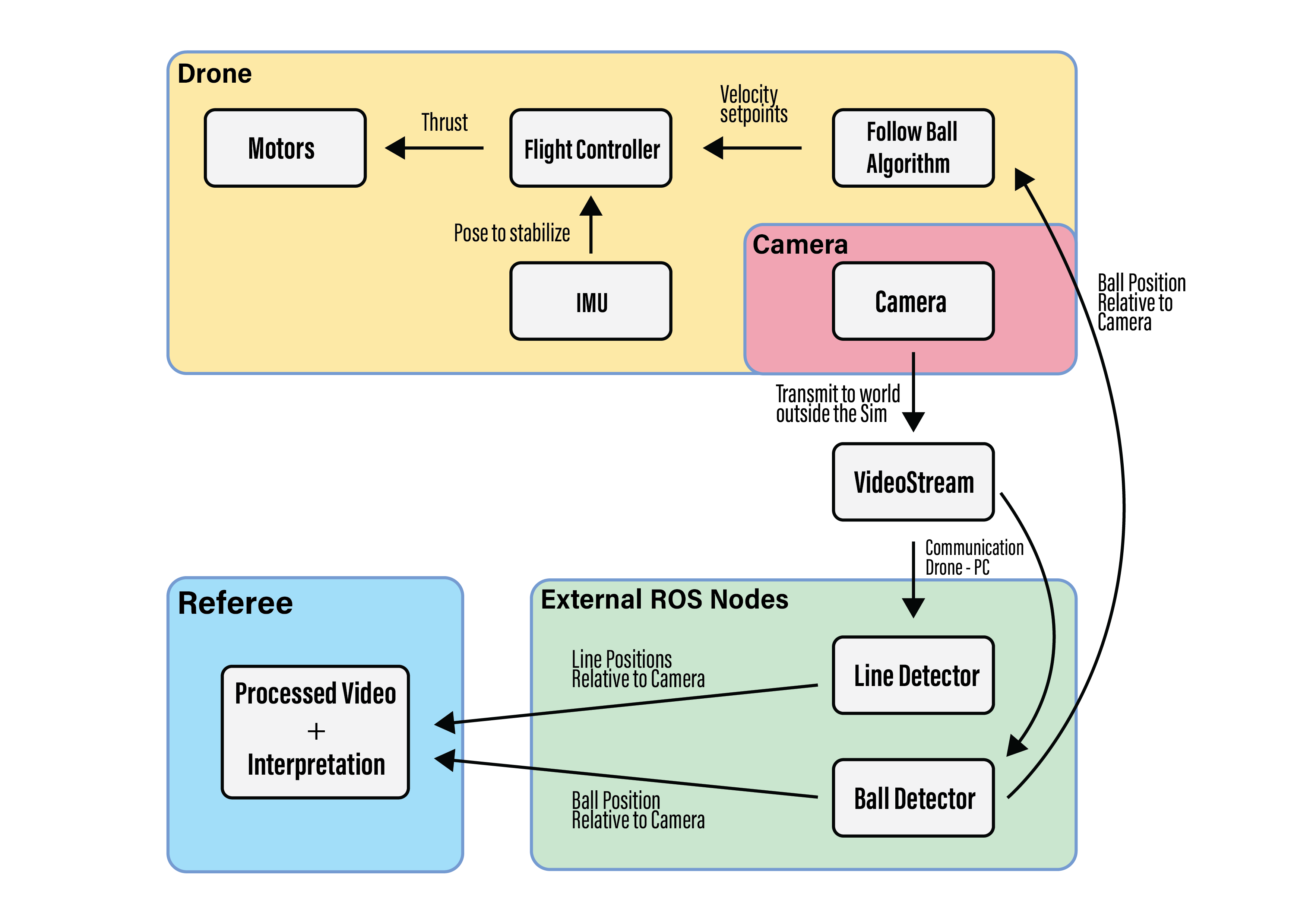
The software architecture of the designed system can be seen in the below figure.

As can be seen in the figure above, the system consists of four main subsystems; The drone itself, the camera on the drone, the external ROS nodes running on a separate PC, and a referee monitoring system.
The drone will start by hovering in the air, it will do this using its inertial measurement unit (IMU) and some additional sensors (for the implementation in real-life these will include an optical flow sensor and a barometer, more about this implementation can be found on the section about the hardware implementation). This unit along with the sensor will continuously send information about the drone's pose to the flight controller. Initially, the flight controller only makes sure that the given information will be used to stabilize the drone into hovering mode by sending trust commands to the four independent motors of the drone.
The camera that is attached to the drone transmits a video stream. This video stream will be picked up by the nodes that are running on the external PC.
On the PC the video stream will be processed so ball and line positions can be extracted. The position and radius of the ball within the video stream (that is relative to the drone) will be sent together with the detected lines to the referee's system.
On the referee's system, the earlier information found will be presented in a processed video stream accompanied by an interpretation of what this stream displays e.g. the ball is at a specific location, and is crossing a line.
The ball position and radius with respect to the camera will also be sent to the drone. Here it is received by the node that will determine based on the ball position how to orientate the drone. It will do this interpreting the information and deciding how to move the drone to get a better perspective of what is happening. This algorithm will then give velocity setpoints (to start rolling, pitching, yawing, or a combination thereof) to the flight controller that will take care of those.