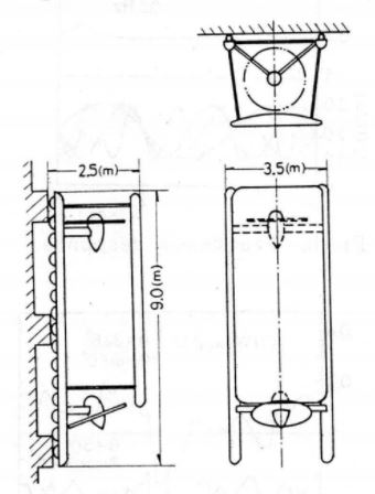
A wall climbing robot for inspection use
An example of conceptual model is shown in figure 1. It has a long body and many wheels to get over the irregularities on a wall surface. A part of wheels can touch to the top of convex part on the wall, and the whole weight is supported by the vertical component of thrust force. The movement will be done by the use of a conventional thruster. A conventional thruster is a combination of engine and propeller. A small jet engine and rocket motor can be available as the thrusters, but they are expensive and noisy compared with a conventional one. Same goes with propeller choice, trade-off in the design are necessary.
When cleaning a high rise building the robot will face strong winds. If such strong winds are predicted on a wall where the robot is cleaning, then a control system against the wind force is very important. Winds are examined by computer simulations and the actual wind data are given to the controller, and the responses are obtained and required characteristics are determined. Since the control system has a time delay it is very hard to compensate for the winds in response. The thrust force controller is not enough to support the wind force acting on the robot as mentioned above.
A frictional force augmenter is considered for this purpose, which is an airfoil and can produce the lift force to the wall side to increase the frictional force of wheels. Its lift force is proportional to wind speed and doesn’t have any time lag for the velocity changes of the wind, so it is a sensible controller and actuator.
The basic investigation of a wall climbing robot is carried out, and the followings are concluded.
(1) At first the mechanism of robot is discussed. To compensate the wind force acting on the robot, the thrust force is controlled, and both a frictional force augmenter and a damper are used to give an additional supporting force.
(2) The characteristic of augmenter was examined by the wind tunnel testing and it is proved that it can support nearly a half of wind force for high speed wind of U = 30-40 (m/s) (with U being the velocity change of the wind).
(3) A transient response of the robot controller is examined by a step and ramp functions, and the supporting force Fs < 0 appears for the abrupt change of wind speed. These situations mean the slipping of the robot.
(4) A frequency response is also examined and it is shown that the frequency around 1Hz is important for the model.
(5) The response to an actual turbulent wind is also obtained, and it is shown that the robot can be supported in a turbulent and high speed wind of U = 5-40 (m/s) by controlling the thrust force.
(6) A robot model was constructed and tested on the wall to inspect the wall surface. It was proved that the robot model could be controlled easily by a radio controller through an on-board computer.
