0LAUK0 PRE2018 3 Group 13 Braille mechanisms
Braille mechanism
The idea of a mechanism that dynamically creates Braille output has been worked out in all kinds of ways by existing patents over the years. We will be discussing some of the more common mechanisms and eventually decide on the one that fits our scenario the most by looking at the trade-offs.
Piezo-electric actuators
Piezo-electric actuators for the use of Braille displays were introduced in 1979 and still mostly constitute the operating principle of commercially available Braille displays [1]. In order to get a complete view on the implementation of this actuating mechanism, we take the TactoBook [2] system which presents the use of piezo-electric ultrasonic actuation. The dimensions they have taken for their Braille configuration is 2.54 mm spacing between pins and 0.7 mm vertical strokes.

By using a relay-lever mechanism with the piezo-electric benders, we can move the pin up when voltage is supplied and move it down back to its original position when the power is off due to the self-weight of the lever mechanism. However, there is a design drawback with this mechanism as this implementation requires much space and may therefore make the entire product less portable.
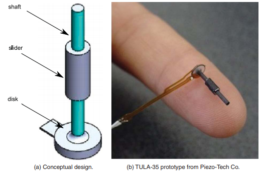
In order to overcome the compactness problem, the paper discusses the use of piezo-electric linear actuators instead. Here the actuator consists of a shaft, a moving slider and a piezo-electric ceramic disk. Its entirety is very small and lightweight as it is 2.4 mm diameter, 11.6 mm in length and 370 mg in mass. There are no burdensome relay levers that require the use of more space.

So the ceramic disk has a rigid case surrounding the transducer, which vibrates when voltage is applied. This creates vertical movement, allowing the slider and shaft to move up and downwards. The motion is based on the principle of inertia displacement by square wave electric potential [3]. Both the slider and shaft move upwards when the power is on, if it’s turned off then the shaft will be moving downwards while the slider remains at its global position due to its inertia. The power will be turned back on to move both the shaft and slider upwards and the power will be turned off again, which only moves the shaft downwards. Through this cycle we can move the slider and consequently move the pin up and down as the slider is attached to the plastic pin. The reverse motion can be achieved by simply inverting the cycle’s electric potential.
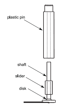
Here the assumption is made that the plastic pin is bi-stable. This means that we only require energy to changing one position from another. In order to acquire this, we assume that the friction between the slider and shaft is such that the slider retains its position without the use of power. To create an actual compact device with this mechanism, you would need the following design goals:
Each pin is independently addressed and their motion should not limit the motion of neighbouring pins
Each pin must be placed within a Braille cell and have convenient access to electricity without influencing other pins
Pins should be easily removable when necessary
The proposed design concept is to use multiple layers, where the first layer acts as the contact surface where pins will poke through and the second acts as a guiding structure for the pins. The consequent layers will have two pins each, while the bottom layer acts as a base of the cell.
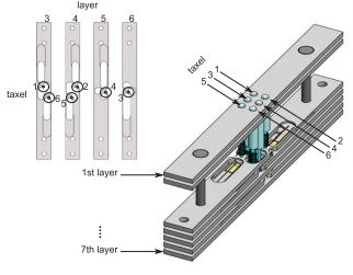
As a result, a prototype of this concept would have the following performance:
108 mN pull force
5 Hz refreshable bandwidth
0.7 mm strokes
The product is available through manufacturer quotes and not to the general consumer, so there is a wide price range and model variety. As of now, the rough estimate is around $50 per actuator which is quite expensive.
Electro-magnet actuators
To discuss the viability of electro-magnet actuators, we have looked at various existing patents from the literature study that utilize this mechanism in order to consider understand the core workings.
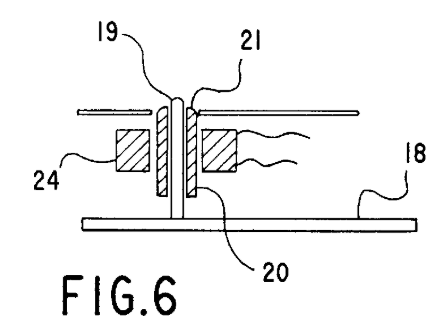
We see that the general use of electro-magnets is simple and take the portable reading device for the blind patent [4] as an example.

In the figure we see an expanded view of the housing concept for the Braille pins (19). These non-metallic pins (19) are attached to the plate (18) to keep them interdependent. The tips of the pins are always sticking through the holes (21) and form small dots. Large dots will be representing the actual Braille letters are moving cores (20) of micro-electromagnets (7) and its tip will be rounded. These moving cores (20) are hollow and crossed by the non-metallic pin (19), in order to allow the dots to remain protruding from the holes (21) when the mechanism is not actuated. When the micro-electromagnets are energized, the large dot made by the moving core (20) will protrude which causes the small dot to disappear. To reset the moving core back to the resting position when the micro-electromagnet is no longer energized, we can use a leaf spring that acts on a groove made in the moving core (20)
This actuator construction can be generalized as follows. The moving part is an axially magnetized cylindrical permanent magnet and there are two coils connected in series in such a way that they create magnetic flux of opposite directions in the region of the permanent magnet. Consequently, the permanent magnet will move either up or down depending on the polarity of the power supply. In order to move up, the coils should create flux in the air gap and to move down the polarity is simply reversed. This motion is transferred to the Braille dot using a non-metallic shaft to prevent magnetic interference.
Cam follower actuator
The mechanical linear actuator is the simplest actuator that would fit as a Braille mechanism, as it creates motion in a straight line. These typically operate by converting rotational motion into linear motion by using screws or gears. We consider the cam and follower assembly which consists of five basic parts; the groove, cam, follower, spring and pin. Here we create a toggled system that only has two states, where the pin is either protruding or not. As shown in the figure [5], the groove holds all parts, while the cam pushes the follower to the state it is not in. The spring is used to ensure that the follower can transition states every time the cam is active.
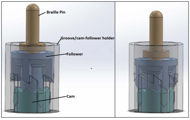
With the mechanism, we can disregard concerns of keeping active protruding Braille dots in place when the user is pressing on them while reading. Since the follower is resting on the cam’s grooves, it is locked in place until it is pushed by the cam.
Comparison
Linear piezo-electric actuators are the most compact and lightweight, but their high costs make it unreasonably expensive for a full display Braille product so we will not opt for this actuator.
Micro-electromagnets and cam followers are more accessible to general consumers than linear piezo-electric actuators and they are also significantly cheaper as the prices are around $10 per actuator. They do however take relatively more space, but this varies per actual product.
The main advantage of the cam follower actuator is that the protruding Braille dot state is very robust, as the user cannot force the dot down due to the locked grooves of the cam part. However, this can also be negated in the use of micro-electromagnets by having sufficient magnetic force keeping the dot protruding.
We can assume that the mechanism will be used very often, so by keeping the degradation of the performance in mind we can make the decision. The cam follower actuator uses mechanical parts that can degrade after many uses and are more prone to hardware failure. Meanwhile, the micro-electromagnets mechanism’s moving part is only dependent of the permanent magnet and the coils. Magnets generally remain magnetic for hundreds of years and its most prominent performance degradation factor is due to the reduction of its volume, which is not of a concern if we have working design. Here we don’t have many risks of hardware failures even after long extended uses and from the user’s perspective it would be preferable to have a longer-lasting product that highly unlikely requires repair in the future. Hence, we shall opt for the micro-electromagnet actuators for our Braille robot mechanism.
Actuator specification
As mentioned above, we will be making use of electromagnetic linear actuators but there are many different possible implementations with this mechanism. We will be considering the voice coil actuators and solenoids as they are both highly similar to the patent on micro-electromagnetic actuators for the braille display.
Voice coil actuators
Voice coil actuators or also known as non-commutated DC linear actuators consist of two assemblies. A permanent magnetic assembly, which contains the permanent magnets and ferrous steel and there is a coil assembly. As current flows through the coil assembly it will interact with the permanent magnetic field since it produces magnetic flux from the coil windings, which consequently generates a force vector perpendicular to the direction of the current based on the Lorentz force principle. This force vector can be reversed simply by changing the polarity of the current that flows through the coil. Either one of the assemblies can be used as the moving part in the voice coil actuator.
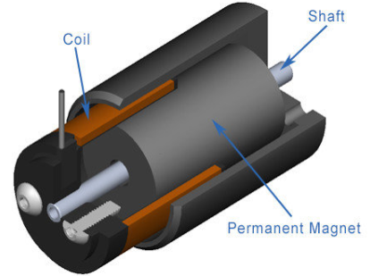
The amount of force generated can be expressed as F = k*B*L*I*N where
F = force (Newton)
k = force constant
B = magnetic flux density (tesla)
L = wire length (meter)
I = current (Ampere)
N = number of conductors
With a given voice coil, all the parameters are fixed except the current. Therefore, we can see that the generated force is directly proportional to the input current. This actuator is typical for fixed-stroke applications with maximum strokes of approximately 15 cm. The generated force is constant throughout the stroke, with exceptions of the beginning and the end of the stroke.
Solenoid
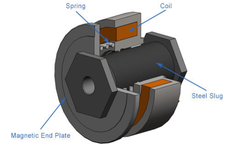
Solenoids consist of a coil contained in a ferrous steel housing and a movable steel slug. Here magnetic fields are generated by applying current to the coil, the magnetic field intensity is determined by the amount of force that can be generated by the solenoid. They can create high forces at much shorter strokes than voice coil actuators, however this operation is unidirectional and when the power is turned off the force drops to zero. In order to return to the opposite direction a spring is needed. Solenoids also have a rapidly declining force output throughout the total displacement and are therefore only typically used for strokes less than 1.5 cm.
Comparison
When we compare the attributes of both actuators, we see that voice coil actuators have a constant force, the force is bidirectional and the stroke lengths can be considerably longer than solenoids. Meanwhile, solenoids can have higher force and operate with very short strokes that are within our range for the use of braille dots.
Our application only requires a compact linear actuator that is capable of accurately moving a shaft within the range of a millimeter and to be able to keep the shaft position fixed while there is a small downwards force applied on it (due to the blind person reading it). We cannot meet both requirements with the sole use of the actuator itself as the braille dot, therefore we would need these actuators to push a cam follower mechanism that puts the dot in a protruding state.
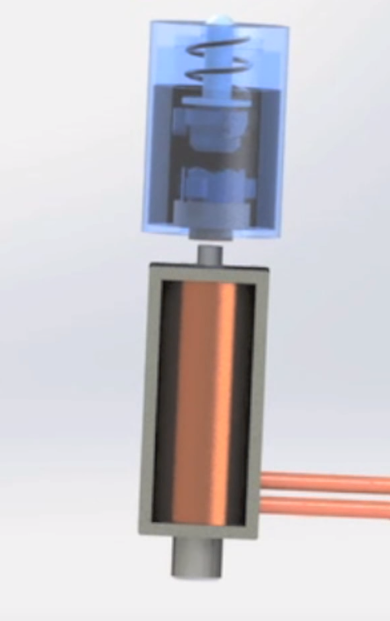
Knowing the fact that voice coil actuators usually cost more than solenoids and that solenoids are an appropriate solution to our problem, we have decided to make use of solenoids to change the states in the cam follower braille dot.
Technical specification for braille dot
1x Solenoid
- Model: ROB-11015 [6]
- Voltage: 5V DC
- Current: 1.1 A
- Power: 5.5 W
- DC Resistance: 4.5 Ohm
- Dimension: 20.00mm L x 11.00m W x 12.00mm H
- Stroke length: 4.5 mm
- Shaft diameter: 4.0 mm
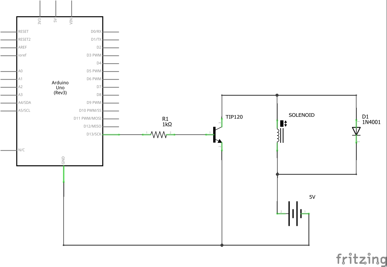
Despite the 5V, it cannot be powered from the Arduino as it draws too much current and when it’s turned off it produces destructive voltages. Therefore we will use an external 5V power supply.
1x 1k Ohm Resistor
Arduino Uno can pass a maximum of 40 mA from a pin.
1x 1N4001 Diode
Only allows current to flow in one direction in order to prevent frying the Arduino when the current is turned off.
1x NPN Transistor
- Model: TIP120 [7]
- Collector-Emitter Voltage Max: 60 V
- Emitter-Base Voltage: 5 V
- DC Current Max: 0.12 A
References
1. Tetzlaff, J.F.: Patent US 4283 178 A (1981)
2. Veláquez R., Hernández H., Preza E. (2012), A portable piezoelectric tactile terminal for Braille readers, Applied Bionics and Biomechanics 9, pp 45-60. Available at: http://downloads.hindawi.com/journals/abb/2012/637851.pdf
3. H. Ko, S. Kim, S. Borodinas, P. Vasiljev, C. Kang and S. Yoon, A novel tiny ultrasonic linear motor using the radial mode of a bimorph, Sensors and Actuators A 125 (2006), 477–481.
4. Parienti R. (1999). U.S. Patent No. US6159013A. Available at: https://patents.google.com/patent/US6159013
5. Mubvuma T.H., Molter L., Alternative Actuators for Braille Devices. Available at: https://scholarship.tricolib.brynmawr.edu/bitstream/handle/10066/14255/Mubvuma_thesis_2014.pdf?sequence=1&isAllowed=y
6. Solenoid ROB-11015 datasheet from sparkfun https://cdn.sparkfun.com/datasheets/Robotics/ZHO-0420S-05A4.5%20SPECIFICATION.pdf
7. NPN transistor TIP120 from adafruit https://cdn-shop.adafruit.com/datasheets/TIP120.pdf
