0LAUK0 2018Q1 Group 2 - Prototype
Introduction
This page explains the design-process behind the prototype made during this project. Suggestions for the final design are also given.
Important components that need to be kept in mind when making the prototype are:
- Degrees of Freedom
- Dynamic domain
- Forces
- Manufacturability
- Compatibility
- Simplicity
- Movement
- Kinematics
- Arduino
- Sensors
Degrees of Freedom
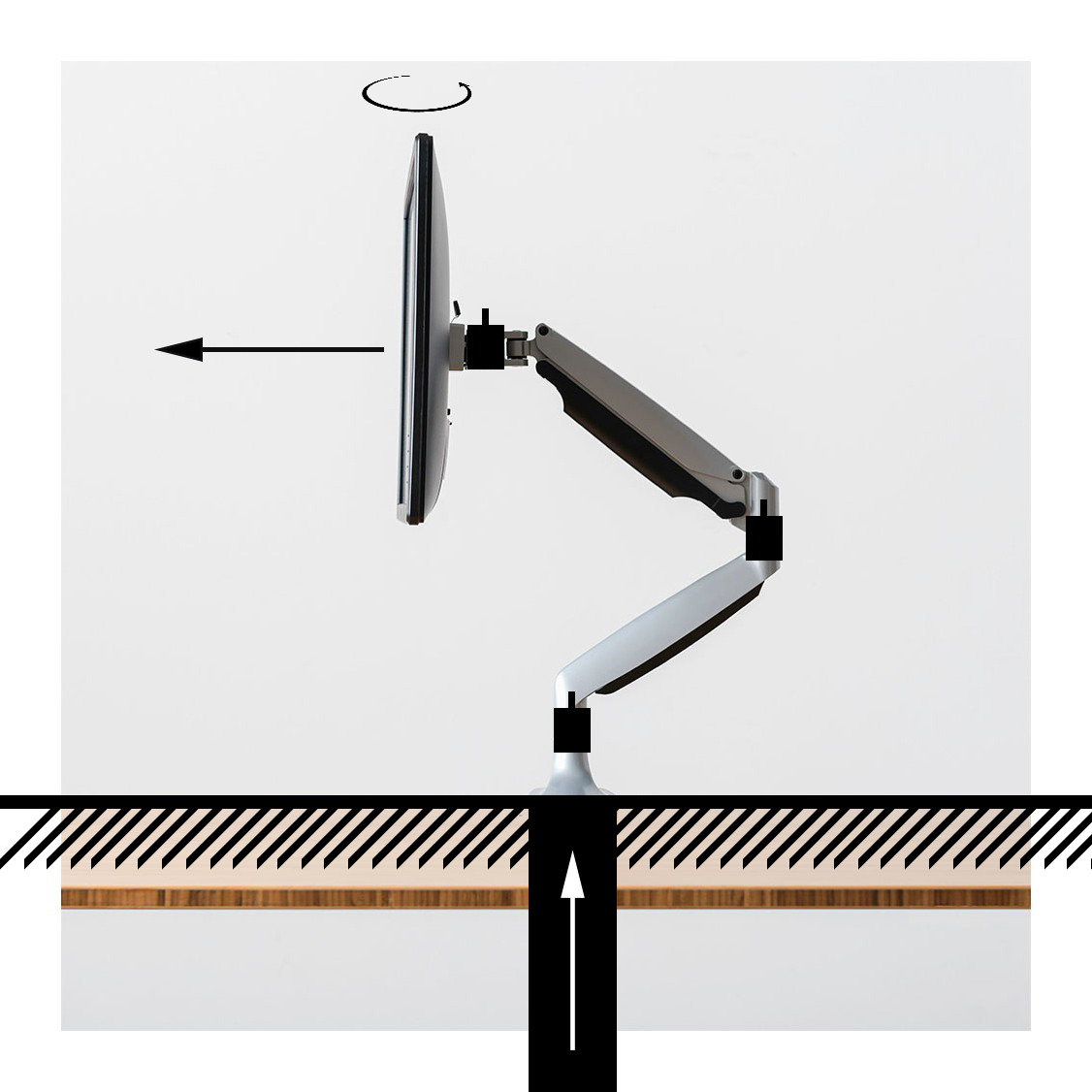
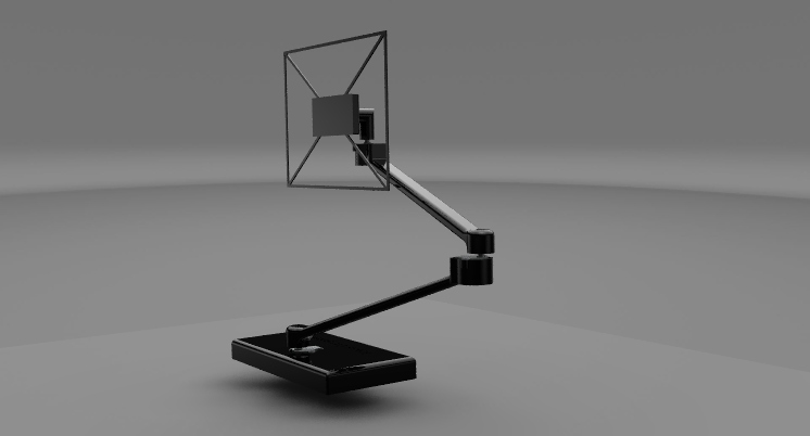
First of all the Degrees of Freedom (DOF) need to be considered. In total there are six DOF that can be included (3 linear x,y,z; 3 rotational), but each DOF makes the manufacturability of the prototype more difficult. Also, not every DOF is important to achieve the end result, which is a monitor arm that reduces neck and back complaints. Looking at the Ideal monitor guidelines, it was decided that the prototype will receive 3 DOF. The first one is a linear movement in the z-direction, to adjust to the body length of a person. The second one is a rotational movement in the xy-plane, to adjust to the angle at which the user is behind his or her desk. The final DOF is a linear radial movement perpendicular to the rotation in the xy-plane. This adjusts the distance at which the monitor is from the user. We have thought of adding a rotational movement in the yz-plane, but this did not seem necessary whereas the linear z-direction already sufficiently comprehends the height adjustment. The DOF are visualized in Mark I prototype.
Dynamic Domain
As with the DOF, the dynamic domain of the prototype is depending on the Ideal monitor guidelines. Taking these guidelines in account, the ideal operational domain (seen from the top view) of the prototype is a semicylinder with a radial distance of approximately 40 cm. This can easily be accomplished by using a 2-link arm with 3 rotational joints that can fully move in the linear y-direction. To move in the linear y-direction we have decided to assume that this can be actuated by the systems that is already implemented in the Gispen TM duo desk.
Forces
To function properly, the prototype should be able to lift the monitor easily from each position without damaging the actuation system. Forces can differ a lot due to change of arm length, and thus higher moments. To make sure this happens, the correct actuation type should be chosen. After also considering hydraulic actuation and servo motors, we have decided to use stepper motors for the prototype. Stepper motors are easy to use and can deliver high torque without gearing. A stepper motor also has a holding torque, which means that the torque will be kept even when no input is given to the motor.
Even though stepper motors are conventional, it is still possible that the full system needs more power to operate. An integrated spring system could be used to subtract the major part of forces needed to move the arm. These spring systems are already implemented in normal monitor arms. It was not possible for us to acquire such an monitor arm, so we decided to build our own. Because of manufacturability we have decided to not make an integrated spring system, but to assume this is implemented in the final design. Because of this, the prototype will be lightweight and carry a dummy monitor instead of a real one.
Manufacturability
We have decided to make the prototype using additive manufacturing because this option was available and this would later on result in easy assembly of all components. First all components were designed using the Computer Aided Design (CAD) software Siemens NX.10. During this process different electronic components were already chosen in order to design the monitor arm around it. The parts were printed from black PLA using an Ultimaker 3 in the TU/e innovation space. For the final design it is advised to use machined aluminium to increase the stiffness of the parts and decrease the tolerance.
Compatibility & Simplicity
The compatibility of the monitor arm and it's components is very important. As stated earlier, the monitor arm will be implemented in the Gispen desks and will also be operated from one control center and should cooperate with different types of software. The system should be compatible with CtrlWORK and Chairgonomics This cooperation is assumed to work for the final design. For the prototype the monitor arm will run on a small computer with it's own software. The prototype is also kept as simple as possible, in orde to reduce the chance of failure, tolerances and the time limit in which a working prototype had to be made.
Movement
When the total design is finished and the prototype is ready to be assembled, the movement can be thought out. The movement is based on three main subjects: the kinematics, electronics and sensors. All subjects are made in parallel and should be combined when they are working separately.
Kinematics
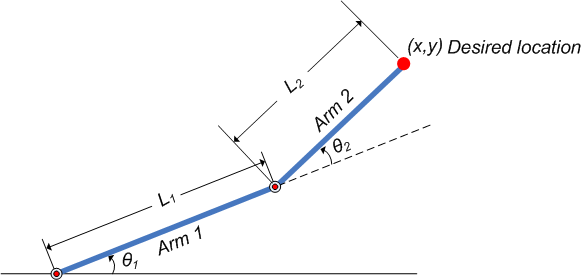
The kinematics describe the coordinatesystem in which the robot arm is able to move. The kinematics are calculated using MATLAB R2017a. This is done with forward and inverse kinematics. The forward kinematics calculates all possible coordinates based on the domain and stepsize in which the stepper motors can move. When an input coordinate is given, the script finds the angles which are closest to this coordinates. The downside of this is that an exact stepsize is needed and that literally all possible combinations are calculated before even using an input. This resulted in matrices with over 8 million arrays, which is not optimal for a small computer.
The inversed kinematics are made the other way around, as it's name implies. The script uses x and y coordinates as input which it converses with trigonometry. A problem with this script is that some the used functions have asymptotes. This results in bad calculations close to certain inputs. To solve this the script is written for different coordinate domains.
Electronics
For the microcontroller we decided to use the Arduino Uno, due to its availability, our prior programming experience with Arduino and cross platform possibilities. Every motor needed a total of 4 digital pins for proper control via Arduino, meaning that a total of 12 digital pins were needed for the 3 stepper motors used in our monitor arm. Exactly the amount of usable digital pins the Arduino Uno has. If more than 12 digital pins were needed, an Arduino Mega would have been necessary, due to the Arduino Uno only having 12 usable digital pins when using Serial Communication as well. More information on the Arduino Uno can be found on this webpage: https://store.arduino.cc/arduino-uno-rev3.
For the motors we decided to use the 28BYJ-48 5V Stepper Motors, mainly due to its availability from the Engineering Design course (4WBB0). What often is a big bottleneck in time is the delivery time needed for various components of a prototype. Also, the delivery time often varies a lot depending on the component that is ordered. To bypass this, the option that is able to be acquired without the bottleneck of delivery time cuts down on the uncertainty of when all the parts have been delivered and allows for earlier experimentation to familiarise oneself with the component in question. Which allows for smoother progress in programming the component. Other reasons why this stepper motor was chosen for our prototype included the small size and sufficient power the motor has for the small prototype of a monitor arm. Specification on the stepper motor, can be found on the webpage: http://robocraft.ru/files/datasheet/28BYJ-48.pdf.
For the drivers we decided to use the ULN2003 Stepper Motor Driver, due to its compatibility with the 28BYJ-48 5V Stepper Motors and its availability from the Engineering Design course (4WBB0). The specification can be found here: https://www.electronicoscaldas.com/datasheet/ULN2003A-PCB.pdf.
For the power supply we used an 5V adapter, due to its inexpensive pricing and immediate availability in the web shop TinyTronics. Since mobility is not really an issue, the adapter simply has to be plugged in, uses power from the net and converts it to power that is usable for the 5V stepper motors.
To increase the performance of the electronics, control solutions from Trinamic could be used. Certain types of motor drivers from Trinamic make use of StealthChop ™, SpreadCycle ™ and StallGuard ™. StealthChop ™ is an solution that reduces the noise made by stepper motors. This is very important since the final design should not distract the user from his/her work. SpreadCycle ™ cahnges the input signal in such a way that transitions from certain commands with new coordinates always go smoothly. In this way the movement of the arm always comes over as calm and will not surprise the user. StallGuard ™ implements an option to use a certain treshhold for as friction force for the monitor arm. This means that we are able to make sure the arm will not break itself or other obstacles in it's path.
Sensors
We measure the distance to the user using a Sharp GP2Y0A02YK0F Distance Measuring Sensor Unit, which can detect distances from 20 to 150 cm. Since it is connected to an Arduino Uno using a analog port we had to write a transformation function to derive the measured distance in meters using the analog signal that the Arduino received. Our programming overview page describes the transformation functions and details about this sensor in more detail. You can also find a link to the spec sheet of this sensor on the programming overview page.


