Integration Project Systems and Control 2013 Group 4
Group Members
| Name: | Student id: | Email: |
| Koen Gruntjens | 0760934 | k.g.j.gruntjens@student.tue.nl |
| Erik van Broekhoven | 0637413 | e.c.v.broekhoven@student.tue.nl |
| Wouter Geelen | 0744855 | w.geelen@student.tue.nl |
| Leroy Hazeleger | 0651762 | l.hazeleger@student.tue.nl |
Planning
February 18 - February 24
- Qualitative analysis of robot
- Derivation of kinematics and dynamics
- Preparation of first experiment session
- Investigate different control-design
- Group meeting
February 25 - March 3
- FRF-measurement and analyse
- Coupled/decoupled experiment
- Non-linearity experiment
- Static friction experiment
- Group meeting
March 4 - March 10
- Continue making FRF-measurements
- Design PID controllers for all joints
- Trajectory planning for all joints
- Group meeting
March 11 - March 17
- Verify trajectory planning (minimum time trajectory)
- Optimization of PID controller
- Group meeting
March 18 - March 24
- Design feedforward controller
- Implementing feedforward controller
- Discuss and design ILC
- Group meeting
Progress
Week 1
- The first step in this project was to identify the pizza-robot by creating a list of all the design requirements of the pizza-robot (to design experiments) such as:
- The pizza is not allowed to fall during transport, therefore the maximum acceleration in directions is limited.
- The robot is not allowed to touch the pizza holding brackets, therefore the trajectory must be designed in such a manner that the pizza-robot does not collide with the brackets.
- 3 pizza's must be transported and the pizzas must be transported as fast as possible (approx. 10-15 [s]). To achieve this a good controller and trajectory for axis have to be designed.
- The controller must be stable.
- The output of the controller is limited for each axis i.e. we are dealing with saturation.
- The accuracy of the pizza-robot end-effector when obtaining a pizza from the brackets should be approximate 5 [mm].
- Identifying limitations of the pizza-robot such as:
- Degrees of freedom to specify the work space of the end-effector.
- Possibly non-linear coulomb and viscous friction.
- The maximum input signals [V] of the motors of the pizza-robot and consequently the maximum velocity/acceleration of each joint.
- To identify the pizza-robot in a more specific way:
- The kinematics of the pizza-robot are derived which are helpful for the trajectory design and determining the dynamics of the pizza-robot using the DH convention.
- A simple model of the pizza-robot is determined to possibly use model-based control design (dynamics of the pizza-robot in terms of the generalized coordinates is difficult, consider a simple model for each joint separately)
- FRF-measurement experiments are prepared (designing a reference trajectory, a stabilizing controller)
- Different types of feedback-control are considered which are usable (and possible with the knowledge of the groupmembers)
Week 2
- As already mentioned in week 1, a simple model is proposed to (possibly) use for model-based control design instead of the dynamics of the pizza-robot in terms of its generalized coordinates since this is too complex and not usable as model-based control design. (for every joint a model, with disturbances from other joints)
- FRF-measurements are performed of each joint with a stabilizing controller and a specific reference trajectory, however large friction is encountered which seems to be not constant along the trajectory of each joint. This influence the FRF-measurements at low frequency. (improve FRF-measurements)
- The deadzone of each axis have been determined.
- It has been determined that the pizza-robot can be treated as a system that is decoupled.
Week 3
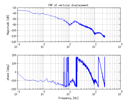
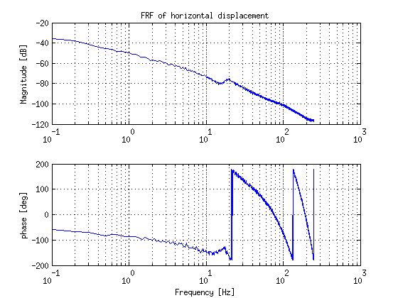
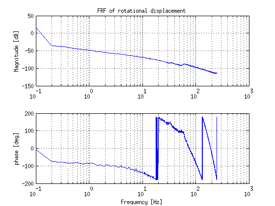
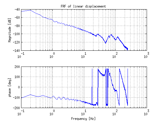
- It took a bit more time for doing the FRF-measurements. Finally we have all FRF's of the joints and all group members designed a stable controller for two joints e.g. such that every joint had at least two controllers made by 2 different members of the group.
| Vertical displacement | Horizontal displacement |

|

|
| Rotational displacement | Linear displacement |

|

|