PRE2022 3 Group5
Group members
| Name | Student id | Role |
|---|---|---|
| Vincent van Haaren | 1 | Human Interaction Specialist |
| Jelmer Lap | 1569570 | LIDAR & Environment mapping Specialist |
| Wouter Litjens | 1751808 | Chassis & Drivetrain Specialist |
| Boril Minkov | 1564889 | Data Processing Specialist |
| Jelmer Schuttert | 1480731 | Robotic Motion Tracking Specialist |
| Joaquim Zweers | 1734504 | Actuation and Locomotive Systems Specialist |
Project Idea
The project idea we settled on is designing a crawler robot to autonomously create 3d maps of difficult to traverse environments so humans can plan routes through small unknown spaces
Our project concept is a guiding robot capable of helping users find rooms/locations. Our concept will be designed with the environment of the university and students in mind. The points we will try to improve on when compared to existing concepts is including stair climbing capabilities and increasing speed as much as possible to not slow down the users.
Project planning
| Week | Description |
|---|---|
| 1 | Group formation |
| 2 | Tasks:
Goals at the end of the week:
|
| break | Carnaval Break |
| 3 | Monday: Split into sub-teams
work started on prototypes for LIDAR, Locomotion and Navigation |
| 4 | Thursday: Start of integration of all prototypes into robot demonstrator |
| 5 | Thursday: First iteration of robot prototype done [MILESTONE] |
| 6 | Buffer week - expected troubles with integration |
| 7 | Environment & User testing started [MILESTONE] |
| 8 | Iteration upon design based upon test results |
| 9 | Monday: Final prototype done [MILESTONE] & presentation |
| 10 | Examination |
User scenario's
Physical contact through crowded spaces
Jack is partially sighted and can see only a small part of what is in front of him. He has recently been helping out fellow students with their field tests which tests a robot guide. Last month he worked with a robot called Visior which helps steer him through his surroundings. Visior is a robot which is inspired and shares its physical features with CaBot.
When Jack used Visior to get to the library to pick up a print request he had to pass through a mediumly-crowded Atlas building since there was an event going on. This went mostly as expected; not too fast and having to stop semi-periodically because of people walking or stopping in front of Visior. The robot was strictly disallowed to purposely make physical contact with other humans. Jack knows this so he learned to step up in these situations and try to kindly ask for the people in front to make way. This used to happen less when he uses his white cane since people would easily identify him and his needs. After Jack arrived at printing room in MetaForum he picked up his print request. He handily put his batch of paper on top of his guiding robot so he didn’t have to carry it himself.
On his way back he almost fell over his guiding robot when it suddenly stopped when a hurried student ran by. Luckily he did not get hurt. When Jack came home after this errand he crashed on his couch after an exhausting trip of anticipating the robot’s quirky behavior.
The next day the researchers and developers of Visior came to ask about his experiences. Jack told them about his experience with Visior and their trip to the library. The developers thanked him for his feedback and started working on improving Visior.
This week they came back with the now new and improved Visior-robot. This version has been installed with a softer exterior and now rides in front of Jack instead of by his side. The developers have made it capable of safely bumping into people without causing harm. They also made it capable of communicating with Jack if it thinks it might have to stop suddenly to make Jack a bit more at ease when traveling together.
The next day Jack used it to again make a trip to the printing space in MetaForum to compare the experience. When passing through the crowded Atlas again (there somehow always seems to be an event there) he was pleasantly surprised. He found it easier to trust Visior now that it was able to communicate the points in the trip where Visior thought they might have to stop or bump into other pedestrians. For example when they came across a slightly more crowded space Visior had guided Jack to walk alongside a flow of other pedestrians. Jack was made aware of the slightly unknown nature of their surroundings by Visior. Then when student suddenly tried to cross their path without looking Visior had unfortunately bumped into their side. Visior gradually slowed their pace down to a halt. Jack obviously felt the bump but was easily able to stay stable due to the prior warning and the less drastic decrease in speed. The student who was now naturally aware of the something moving in their blind spot immediately stepped out of the way and looked at Jack and Visior; seeing the sticker stating that Jack was visually impaired. Jack asked them if they were alright, to which they responded with saying they were fine after which they both went on their way. After picking up his print he went back home. On his way back he had to pass through the small bridge between MetaForum and Atlas in which a group of people were now talking; blocking a large part of the walking space. Visior guided Jack to a small traversable path open besides the group; taking the risk that the person there would slightly move and come onto their path. Visior and Jack could luckily squeeze by without any trouble and their way back home was further uneventful.
When the Developers of Visior came back the next day to check up on him Jack told them the experience was leagues better then before. He told them he found walking with Visior less exhausting then it had been before and found the behavior of it more human-like making it easier to work with.
Familiar guidance advantage
Meet Mark from Croatia He is a Minor Student following Mathematics courses, and lives on (or near) campus Mark is severely near-sighted, being born with the condition he has never seen very well. Mark is optimistic but chaotic. Mark likes his study, and likes playing piano.
Notable details: Mark makes use of a white cain and audio-visual aids to assist with his near-sightedness. He just transferred to TU/e for a minor, and doesn't know many people yet. Mark will only be here a short time for his minor. He has a service dog at home, but does not have the resources, time or connections to provide for it here, and so he left it at home.
Indoors, mark finds it hard to use his cane because of crowded hallways and he dislikes apologizing when hitting someone with his stick, or being an inconvenience to his fellow students. Mark can read and write English fine, but still feels the language barrier.
In a world without our robot mark might have to navigate like this: Mark has just arrived for his 2nd day of lectures. And will be going to the wide lecture hall at Atlas -0.820. Mark again managed to walk to Atlas (as we will not be tackling exterior navigation), and uses his cane and experience to navigate the stairs and rotary door of Atlas, using it to determine the speed and size of the revolving element to get in, and using the cane to determine the position of the doors and opening (https://youtu.be/mh5L3l_7FqE).
Once inside, he is greeted by a fellow student who has noticed him navigating the door. Mark had already started concealing the use of his cane, as he doesn't like the attention and so the university staff didn't notice him. Luckly, his fellow student is more than willing to help him get to his lecture hall. Unfortunately, the student is not well versed in guiding visually impaired around, and it has gotten busy with students changing rooms.
Mark is dragged along to the lecture hall by his fellow student, bumping into other students who don't notice he cannot see them, as his guider is hastily pulling him past the students. Mark almost loses his balance when his guide slips past some other students, narrowly avoiding the trashcan while dragging mark by his arm. Mark didn't see the trashcan, which is not at eye level, and collides with the metal frame while trying to copy the movement of his guider to dodge the other students. He is luckily unharmed, and manages to follow his guide again, untill he is finally able to sit in the lecture hall, ready to listen for another day.
With our robot however: Mark arrives inside Atlas, and is greeted by a fellow student, who noticed him struggling with the door. The student knows there are guidance robots at this building, and helps Mark to a guidance robot clearly waiting by the entrance. He helps mark enter his destination in the interface, and leaves him to go to his own lecture.
The robot greets mark, and tells him instructions in order to follow him. The robot tells him to extend his arm slowly at belly level, until he can feel the robot. The textured design alongside the specifically shaped exterior naturally guide Mark's hand to the specially designated handhold. The robot tells him to grab the hold, using touch technology to confirm this action, the robot proceeds by demonstrating the different haptic and kinetic indicators mark could pay attention to, in order to know the situation around him, as sensed by the robot.
Then, the robot starts the task of getting mark to the lecture hall. It starts moving, its next intended speed and direction through the feedback in the handle. As a result, Mark can anticipate the route the robot will take, similar as to how a guide would apply force to Mark's hand to change direction (find that video again).
The robot has reached the crowd of students moving through the busy part of Atlas. It's primary objective is to get Mark through this, and even though many students notice the robot going through, it still uses clear audio indications to warn students it will be moving through, and notifies mark it goes into some alternate mode through the handle. Mark notices, and thus becomes alert as he also feels that the robot reduces the number of turns it makes, Navigating through the crowd in the most straightforward route it can take. Mark likes this, it is making it easy for him to follow it, and also for others to avoid them.
Still, a sleepy student bumps into the robot as it is crossing. Luckily the robot is designed to contact other students, and it's rounded shape, enclosed wheels (or other moving parts) and softened bumpers prevent harm. The robot does however slightly reduce its pace, and makes an audible noise to let the sleepy student know it touched the robot too hard. Mark also notices the collision, partially because the bump makes the robot shake a little and loose a bit of pace, but mainly because his handle clearly and alarmingly notifies him, Mark also knows the robot will still continue, as the feedback of the handle indicates to him that it is not stopping.
After the robot made a straight line through the crowd, it makes it to the lecture hall. It parks just in front of the door, and tells mark to extend his free hand slightly above hip level, telling him they arrived at a closed door that opens towards them swinging to his right, similarly to how a guide would, so mark can grab the door handle, and with support of the robot open the door. The robot preceeds mark slowly into the space, it goes a bit too fast though, and mark applies force to the handle, pulling it slightly in his direction. The robot notices this, and waits for mark.
After they enter the lecture hall, the robot asks the lecturer to guide mark to an empty seat (and may provide instructions on how to do so). When mark is seated, the robot returns to its spot near the entrance, waiting for the next person.
Users
Guide dog research
This text is based on multiple papers with the communication between robot and handler being central. The most sought after results were: Selecting method of steering guided: (how to indicate sharpness of turns/what kind of obstacles/indicate confidence of free path)
For this research I mainly looked at the function of guide dogs. This being that other options such as humans can communicate clearer with the person with impaired vision. The tasks of a guide dog are[1][2][3]:
- Walk centrally along the pavement whilst avoiding (dynamic) obstacles on the route
- Maintain a steady pace
- Not turn corners unless told so
- Stop at kerbs and steps
- Find doors, crossings and places which are visited regularly
- Bring the handler to elevator buttons
- Judge height and width so you do not bump your head or shoulder
- Help keep you straight when crossing a road - but it is up to you to decide where and when to cross safely
- Move on command, but obediently ignore when dangerous
Dogs obey commands using hand and vocal signals. On our importance of communication for sharpness of turns, what kind of obstacles, and confidence of free path the following answers are provided.
Indicating sharp corners
Nothing really useful has been found on turning sharp corners. Basically dogs guide their handlers by going through first and staying close to the handlers side. That is how the handler goes to go a little bit left or right. An important note is that guide dogs should not turn unless the handler says so. This is important for a guide robot because the handler does not know how to turn. Therefore this should be neglected but communication can be the other way round. Such as the robot saying or using vibrations to show it is about to turn left or right. However it is to be researched if this communication is necessary or the robot simply turning before the blind is enough.
Indicating (dynamic) obstacles
Guide dogs already are told to stop at different static obstacles such as: kerbs, stairs, and lifts. Therefore are protocols and they can be copied. Dynamic obstacles, dogs probably can avoid just like humans. So, it is hard to really say how dogs do it or how they communicate it apart from simply steering.
Indicate confidence of free path
Guide dogs do not really indicate its confidence that the path is free, they simply make sure as well as possible that dynamic objects do not hit their handler. So it is not clear if the robot guide should indicate this. It may have an adverse effect.
Basically, when indicating corners and static obstacles. There is no free wiggle room because some things are already in place with guide dogs. They however can be replaced with other ways but keep this in mind. An important thing for corners is that guide dogs are trained not to take corners unless told so. In the CaBot the robot uses vibration interval to show the sharpness of the turn. With dynamic obstacles and indicating confidence free path (which is kind of the same as dynamic obstacles), there is a lot to play with indicating this to the handler. The guide dog would simply walk around this.
However information on how guide dogs exactly guide is sparse on the internet. It mostly shows a list of what guide dogs are trained to do. So therefore it is not yet clear of what visually impaired people find important when guided. Therefore I would reach out to Visio. There is also some literature I (Wouter) found, but did not had time to reach about guide robots.
State of the Art
Literature Research
| Paper Title | Reference | Reader |
|---|---|---|
| Modelling an accelerometer for robot position estimation | [4] | Jelmer S |
| An introduction to inertial navigation | [5] | Jelmer S |
| Position estimation for mobile robot using in-plane 3-axis IMU and active beacon | [6] | Jelmer S |
| Stepper motors: fundamentals, applications and design | [7] | Joaquim |
| Incremental Visual-Inertial 3D Mesh Generation with Structural Regularities | [8] | Jelmer L |
| Keyframe-Based Visual-Inertial SLAM Using Nonlinear Optimization | [9] | Jelmer L |
| Balancing the Budget: Feature Selection and Tracking for Multi-Camera Visual-Inertial Odometry | [10] | Jelmer L |
| Optical 3D laser measurement system for navigation of autonomous mobile robot | [11] | Boril |
| A mobile robot based system for fully automated thermal 3D mapping | [12] | Boril |
| A review of 3D reconstruction techniques in civil engineering and their applications | [13] | Boril |
| 2D LiDAR and Camera Fusion in 3D Modeling of Indoor Environment | [14] | Boril |
| A Review of Multi-Sensor Fusion SLAM Systems Based on 3D LIDAR | [15] | Jelmer L |
| An information-based exploration strategy for environment mapping with mobile robots | [16] | Jelmer S |
| Mobile robot localization using landmarks | [17] | Jelmer S |
| The Fuzzy Control Approach for a Quadruped Robot Guide Dog | [18] | Wouter |
| Design of a Portable Indoor Guide Robot for Blind People | [19] | Wouter |
| Guiding visually impaired people in the exhibition | [20] | Joaquim |
| CaBot: Designing and Evaluating an Autonomous Navigation Robot for Blind People | [21] | Boril |
| Tour-Guide Robot | [22] | Boril |
| Review of Autonomous Campus and Tour Guiding Robots with Navigation Techniques | [23] | Boril |
Modelling an accelerometer for robot position estimation
The paper discusses the need for high-precision models of location and rotation sensors in specific robot and imaging use-cases, specifically highlighting SLAM systems (Simultaneous Localization and Mapping systems).
It highlight sensors that we may also need: " In this system the orientation data rely on inertial sensors. Magnetometer, accelerometer and gyroscope placed on a single board are used to determine the actual rotation of an object. "
It mentions that, in order to derive position data from acceleration, it needs to be doubly integrated, which tents to yield great inaccuracy.
drawback: the robot needs to stop after a short time (to re-calibrate) when using double-integration to minimize error-accumulation: “Double integration of an acceleration error of 0.1g would mean a position error of more than 350 m at the end of the test”.
An issue in modelling the sensors is that rotation is measured by gravity, which is not influenced by for example yaw, and gets more complicated under linear acceleration. The paper modelled acceleration, and rotation according to various lengthy math equations and matrices, and applied noise and other real-word modifiers to the generated data.
It notably uses cartesian and homogeneous coordinates in order to seperate and combine different components of their final model, such as rotation and translation. These components are shown in matrix form and are derived from specification of real-world sensors, known and common effects, and mathematical derivations of the latter two.
The proposed model can be used to test code for our robot's position computations.
This paper (as report) is meant to be a guide towards determining positional and other navigation data from interia based sensors like gyroscopes, accelerometers and IMU's in general.
It starts by explaining the inner workings of a general IMU, and gives an overview of an algorithm used to determine position from said sensors' readings using integration, showing what intermitted values represent using pictograms.
It then proceeds to discuss various types of gyroscopes, their ways of measuring rotation (such as light inference), and resulting effects on measurements, which are neatly summarized in equations and tables. It takes a similar for Linear acceleration measurement devices.
In the latter half the paper, concepts and methods relevant to processing the introduced signals are explained, and most importantly it is discussed how to partially account for some of the errors of such sensors. It starts by explaining how to account for noise using allan variance, and shows how this effects the values from a gyroscope.
Next, the paper introduces the theory behind tracking orientation, velocity and position. It talks about how errors in previous steps propagate through the process, resulting in the infamously dangerous accumulation of inaccuracy that plagues such systems.
Lastly, it shows how to simulate data from the earlier discussed sensors. Notably though the previous paper already discussed a more accurate and recent algorithm (building on this paper).
Position estimation for mobile robot using in-plane 3-axis IMU and active beacon
The paper highlights 2 types of positioning determination: Absolute (does not depend on previous location) and Relative (does depend on previous location). It goes on to highlight advantages and disadvantages of several location determination systems. It then proposes a navigation system that mitigates as much of the flaws as possible.
The paper continues by describing the sensors used to construct the in plane 3 axis IMU: - x/y accelerometer, - z-axis gyroscope
Then, the ABS is described. It consists of 4 beacons mounted to the ceiling, and 2 ultrasonic sensors attached to the robot. The technique essentially uses radio frequency triangulation to determine the absolute position of the robot. The last sensor described is an odometer, which needs no further explanation.
Then, the paper discusses the model used to represent the system in code. Most notably the system is somewhat easier to understand, as the in-plane measurements mean that much of the robot position's complexity is restricted to 2 dimensions. The paper also discusses the used filtering and processing techniques such as a karman filter to combat noise and drift. The final processing pipeline discussed is immensely complex due to the inclusion of bounce, collision and beacon-failure handling.
Lastly, the paper discusses the result of their tests on the accuracy of the system, which shown a very accurate system, even when the beacon is lost.
Stepper motors: fundamentals, applications and design
This book goes over what stepper motors are, variations of stepper motors as well as their make-up. Furthermore it goes in-depth about how they are controlled.
Incremental Visual-Inertial 3D Mesh Generation with Structural Regularities
According to the authors advances in Visual-Inertial odometry (VIO), which is the process of determining pose and velocity (state) of an agent using the input of cameras has opened up a range of applications like AR drone navigation. Most of VIO systems use point clouds and to provide real-time estimates of the agent’s state they create sparse maps of the surroundings using power heavy GPU operations. In the paper the authors propose a method to incrementally create 3D mesh of the VIO optimization while bounding memory and computational power.
The authors approach is by creating a 2d Delaunay triangulation from tracked keypoints, and then projecting this into 3d, this projection can have some issues where points are close in 2d but not in 3d, this is solved by geometric filters. Some algorithms update a mesh for every frame but the authors try to maintain a mesh over multiple frames to reduce computational complexity, capture more of the scene and capture structural regularities. Using the triangular faces of the mesh they are able to extract geometry non-iteratively.
In the next part of the paper they talk about optimizing the optimization problem derived from the previously mentioned specifications.
Finally the authors share some benchmarking results on the EuRoC dataset which are promising as in environments with regularities like walls and floors it performs optimally. The pipeline proposed in this paper provides increased accuracy at the cost of some calculation time.
Keyframe-Based Visual-Inertial SLAM Using Nonlinear Optimization
In the robotics community visual and inertial cues have long been used together with filtering however this requires linearity while non-linear optimization for visual SLAM increases quality, performance and reduces computational complexity.
The contributions the authors claim to bring are constructing a pose graph without expressing global pose uncertainty, provide a fully probabilistic derivation of IMU error terms and develop both hardware and software for accurate real-time slam.
The paper describes in high detail how the optimization objectives were reached and how the non-linear SLAM can be integrated with the IMU using a chi-square test instead of a ransac computation.
Finally they show results of a test with their developed prototype which shows that tightly integrating the IMU with a visual SLAM system really improves performance and decreases the deviation from the ground truth to close to zero percent after 90m distance travelled.
Balancing the Budget: Feature Selection and Tracking for Multi-Camera Visual-Inertial Odometry
The authors from this paper propose an algorithm that fuses feature tracks from any amount of cameras along with IMU measurements into a single optimization process, handles feature tracking on cameras with overlapping fovs, a subroutine to select the best landmarks for optimization reducing computational time and results from extensive testing.
First the authors give the optimization objective after which they give the factor graph formulation with residuals and covariances of the IMU and visual factors. Then they explain how they approach cross camera feature tracking. This is done by projecting the location from 1 camera to the other using either stereo camera depth or IMU estimation, then the it is refined by matching it with to the closest image feature in the camera projected to using Euclidian distance. After this it is explained how feature selection is done, this is done by computing a jacobian matrix and then finding a submatrix that preserves the spectral distribution best.
Finally experimental results show that with their system is closer to the ground truth than other similar systems.
This paper presents an autonomous mobile robot, which using a 3D laser navigation system can detect and avoid obstacles in its path to a goal. The paper starts by describing in high detail the navigation system- TVS. The system uses a rotatable laser and scanning aperture to form laser light triangles, which are formed due to the reflected light of the obstacle. Using this method the authors were able to obtain the information necessary to calculate the 3D coordinates. For the robot base, the authors used Pioneer 3-AT, four-wheel, four-motor ski-steer robotics platform.
After this the authors go in-depth on how the robot avoids obstacles. Via the usage of optical encoders on the wheels and a 3-axis accelerometer, the robot keeps track of its travelled distance and orientation. Via IR sensors the robot can detect obstacles that are a certain distance in front of it, after which it performs a TVS scan to avoid the obstacle. The trajectory the robot follows to avoid the obstacle is calculated using 50 points in the space in front of it, which are used to form a curve, which the robot then follows. Thus after the robot starts-up, it calculates an initial trajectory to the goal location, after which it recalculates the trajectory, whenever it encounters an obstacle. Finally the authors go over their results from simulating this robot in Mathlab as well as analyse its performance.
A mobile robot based system for fully automated thermal 3D mapping
This paper showcases a fully autonomous robot, which can create 3D thermal models of rooms. The authors begin by describing what components the robot uses, as well as how the 3d sensor (a Riegl VZ-400 laser scanner from terrestrial laser scanning) and the thermal camera (optris PI160) are mutually calibrated. Both cameras are mounted on top of the robot, together with a Logitech QuickCam Pro 9000 webcam. After acquiring the 3D data, it is merged with the thermal and digital image via geometric camera calibration. After that the authors explain the sensor placement. The approach of the paper to the memory-intensive issue of 3 planning is to combine 2D and 3D planning- the robot would start off by only using 2D measurements, once it detects an enclosed space however it would switch to 3D NBV (next best view) planning. The 2d NBV algorithm starts off with a blank map, and explores based on the initial scan, where all inputs are range values parallel to the floor, distributed on the 360 degree field of view. A grid map is used to store the static and dynamic obstacle information. A polygonal representation of the environment stores the environment edges (walls, obstacles). This NBV process is composed of three consecutive steps- vectorization (obtaining line segments from input range data), creation of exploration polygon, selection of the NBV sensor position- choosing the next goal. The room detection is grounded in the detection of closed spaces in the 2D map of the environment. Finally the authors showcase their results from their experiments with the robot, showcasing 2D and 3D thermal maps of building floors. The 3D reconstruction of which is done using Marching Cubes algorithm.
A review of 3D reconstruction techniques in civil engineering and their applications
This paper presents and reviews techniques to create 3D reconstructions of objects from the outputs of data collection equipment. First the authors researched the currently most used equipment for getting the 3D data- laser scanners (LiDAR), monocular and binocular cameras, video cameras, which is also the equipment that the paper focuses on. From this they classify two categories for 3D reconstruction based on cameras- point-based and line-based. Furthermore 3D reconstruction techniques are divided into two steps in the paper - generating point clouds and processing those point clouds. For generating the point clouds: For monocular images - feature extraction, feature matching, camera motion estimation, sparse 3D reconstruction, model parameters correction, absolute scale recovery and dense 3D reconstruction feature extraction- gaining feature points, which reflect the initial structure of the scene. Algorithms used for this are Feature point detectors and feature point descriptors. Feature matching- matching feature points of each image pair. Camera motion estimation is used to find out the camera parameters of each image. The Sparse 3D reconstruction step is to compute the 3D location of points using the feature points and camera parameters, generating a point cloud. This is done via the triangulation algorithm. Then the model parameters correction step is to correct the camera parameters of each image. This step leads to precise 3D locations of points in the point cloud. Absolute scale recovery aims to determine the absolute scale of the sparse point cloud by using the dimensions/points of absolute scale in the sparse point cloud. Finally using all of the above is used to generate a dense point cloud. For stereo images, the camera motion estimation and absolute scale recovery steps are skipped, and instead we need to calibrate the camera before feature extraction. After this the authors explain how to generate point clouds from video images. in Techniques for processing data, the authors showcase a couple of algorithms for data data processing. For point cloud processing they use ICP. For Mesh reconstruction- PSR, for point cloud segmentation- they divide the algorithms into two categories- feature-based segmentation (region growth and clustering, K-means clustering) and model-based segmentation (Hough transform and RANSAC). After this the authors go in depth on applications of 3D reconstruction in civil engineering such as reconstructing construction sites and reconstructing pipelines of MEP systems. Finally the authors go over the issues and challenges of 3D reconstruction.
2D LiDAR and Camera Fusion in 3D Modelling of Indoor Environment
This paper goes over how to effectively fuse data from multiple sensors in order to create a 3D model. An entry level camera is used for color and texture information, while a 2D LiDAR is used as the range sensor. To calibrate the correspondences between the camera and LiDAR, a planar checkerboard pattern is used to extract corners from the camera image and intensity image of the 2D LiDAR. Thus the authors rely of 2D-2D correspondences. A pinhole camera model is applied to project 3D point clouds to 2D planes. RANSAC is used to estimate the point-to-point correspondence. Using transformation matrices the authors match the color images of the digital camera to with the intensity images. B aligning a 3D color point cloud in different location, the authors generate the 3D model of the environment. Via a turret widow X servo, the 2D LiDAR is moved in vertical direction for a 180 degree horizontal field of view. The digital camera rotates in both vertical and horizontal directions, to generate panoramas by stitching series of images. In the third paragraph the authors go over how they calibrated the two image sources. To determine the rigid transformation between camera images and 3D points cloud a fidual target is used, RANSAC is used to estimate outliers during calibration process and a checkerboard with 7x9 squares is employed to find correspondences between LiDAR and camera. Finally the authors go over their results.
A Review of Multi-Sensor Fusion SLAM Systems Based on 3D LIDAR
This paper is a review of multiple SLAM systems from which their main vision component is a 3D LiDAR which is integrated with other sensors. LiDAR, camera and IMU are the 3 most used components and all have their advantages and disadvantages. The paper discusses LiDAR-IMU coupled systems and Visual-LiDAR-IMU coupled system, both tightly and loosely coupled.
Most loosely coupled systems are based on the original LOAM algorithm by J. Zhang et all, these systems are new in terms of that the paper by Zhang is from 2014, but there have been many advancements in this technology. The LiDAR-IMU systems often use the IMU to increase the accuracy of the LiDAR measurements and new developments involve speeding up to ICP algorithm to combine point clouds with clever tricks and/or GPU acceleration. The LiDAR-Visual-IMU systems use the complementary properties of LiDAR and camera’s, LiDAR needs textured environments while visions sensors lack the ability to perceive depth, thus the cameras are used for feature tracking and together with LiDAR data allow for more accurate pose estimation.
In contrast to the speed and low computational complexity of loosely coupled systems, tightly coupled systems sacrifice some of this for greater accuracy. One of the main points of these systems is a derivation of the error term and pre-integration formula for the IMU, this can be used to increase accuracy of the IMU measurements by estimating the IMU bias and noise. For LiDAR-IMU systems this derivation is used for removing distortion in LiDAR scans, optimizing both measurements and many different approached to couple the 2 devices to obtain greater accuracy and computation speed. The LiDAR-Visual-IMU use strong correlation between images and point clouds to produce more accurate pose detection.
The authors then do performance comparisons on SLAM datasets where most recent SLAM systems appear to estimate pose really close to the ground truth even over distances of several 100 meters.
An information-based exploration strategy for environment mapping with mobile robots
This paper proposes a mathematically oriented way of mapping environments. Based on relative entropy, the authors evaluate a mathematical way to produce a planar map of an environment, using a laser range finder to generate local point-based maps that are compiled to a global map of the environment. Notably the paper also discusses how to localize the robot in the produced global map.
The generated map is a continuous curve that represents the boundary between navigable spaces and obstacles. The curve is defined by a large set of control points which are obtained from the range finder. The proposed method involves the robot generating and moving to a set of observation points, at which it takes a 360 degree snapshot of the environment using the range finder, finding a set of points several specified degrees apart, with some distance from the sensor. The measured points form a local map, which is also characterised by the given uncertainty of the measurements. Each local map is then integrated into the global map (a combination of all local maps), which is then used to determine the next observation point and position of the robot in global space.
The researches go on to describe how the quality of the proposal is measured, namely in the distance traveled and uncertainty of the map. The uncertainty is a function of the uncertainty in the robot's current position, and the accuracy of the range finder. The robot has a pre-computed expected position of each point, and a post-measurement position of each point, which is then evaluated through relative entropy to compute the increment of the point-information. This and similar equations for the robot's position data are used to select the optimal points for observing the environment. Lastly, the points of each observation point are combined into one map, by using the robot's position data.
Mobile Robot Localization Using Landmarks
The paper discusses a method to determine a robot's position using landmarks as reference points. This is a more absolute system than just inertia based localization. The paper assumes that the robot can identify landmarks and measure their position relative to each other. Like other papers, it highlights its importance due to error accumulation on relative methods.
It highlights the robot's capability to: - Find landmarks - Associate landmarks with points on a map - Use this data to compute its position.
It uses triangulation between 3 landmarks to find its position, with low error. The paper also discusses how to re-identify landmarks that were misjudged with new data. The robot takes 2 images (using a reflective ball to create a 360 image), and solves the correspondence problem (identifying an object from 2 angles) to find its location. In the paper, the technique is tested in an office environment.
The paper discusses how to perform triangulation using an external coordinate system and the localisation of the robot. The vectors to the landmark are compared and using their angle and magnitude the position can be computed. Next, the paper discusses the same technique, adjusted for noisy data. The paper uses Least-Squares to derive an estimation that can be used, evaluating the robot's rotation relative to at least 2 landmarks. The paper then evaluates the expected distribution in angle-error and position on each axis, to correct for the noise, using the method described above.
The Fuzzy Control Approach for a Quadruped Robot Guide Dog
This basically makes a robot guide dog. Think of Spot from Boston Dynamics with a leash that is trained to guide blind people. A good thing for this is that spot has proven to be able to walk stairs so it should be fast. Problem is that it is hard to guide blind people. This is their design:
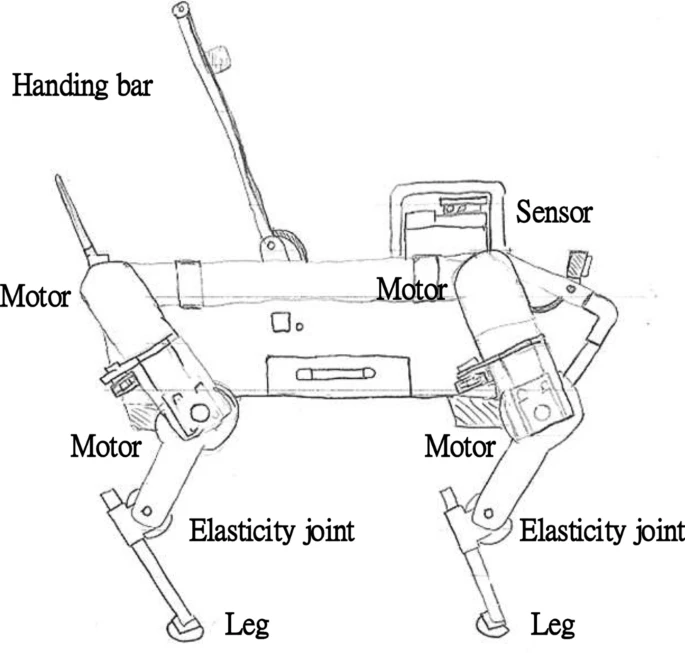
The paper also gives a ‘fuzzy’ control process which makes sure that variation in road surfaces would not affect the dog. The rest of the paper shows how this controller can be designed, it does not show how to guide a blind person.
Their conclusion on what they did shows that their fuzzy algorithm improved how smooth the dog walked.
Design of a Portable Indoor Guide Robot for Blind People
This design takes the guide dog replacement differently. By not replacing it with a dog quadruped robot. This design is mainly aimed at indoors. This paper also did some research on what blind people need. A survey conducted for example says that 90% of people worry about obstacles in the air while travelling. This is the design they came up with:
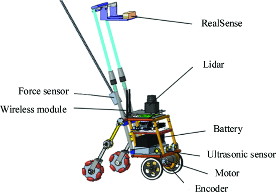
This robot is foldable and has an unfolded height of 700 mm. Further the mechanical design is well explained. This design has no real stair walking capabilities.

This image shows how the robot should be controlled. And they give a whole framework on path planning with cost functions and testing on the traction.
The conclusion stated that the robot did well and it was a low cost, convenient-to-carry, and strong perception blind guide robot.
Guiding visually impaired people in the exhibition
This paper talks about a robotic guide used to help (partially) blind people navigate an exhibition (a noisy, crowded (4 square meters/person), unfamiliar environment). These people are often faced with the challenge of maintaining spatial orientation; ‘the ability to establish awareness of space position relative to landmarks in the surrounding environment’. The paper proposes that supporting functional independence of these people can thus be achieved by ‘providing references and sorts of landmarks to enhance awareness of the surroundings’.
The technology used by this paper to achieve this is a handheld device capable of radio-frequency localization. To prepare the environment a RFID sensor was placed for each 300 square meters (~17x17 m area) at points of interest, services and major areas. The paper does not go into the details of how the localization is done but an educated guess would be that the guiding devices carried by the guided persons are scanned by these fixed sensors which then communicate to calculate the position of the guided. Keep in mind this exhibition took place in 2006, but they found a resolution of 5 meters (minimal distance between distinguishable tags).
The interface of the device makes use of hardware buttons, which they find a solution suited for visually impaired people. Apart from standard navigation and audio control buttons, the device was also equipped with a button which gives quick access to an emergency number.
In this particular use-case the device guided people using an event-system which would ask the user if they wanted to hear a description of their environment. This event would trigger when the handheld device would recognize signals from local sensors. This description would include:
- an extended title
- the description of the point of interest
- one or more extended descriptions
- descriptions to invite and spatially guide the user near the featured flowers and plants.
The device would also describe near points of interest such as crossroads, entrances, exits, restaurants, toilets etc. such that the user can create their own mental map of their surroundings allowing them to build and follow their own path; being unconstrained by the predefined path.
To overcome noise the user was provided with headphones. Another problem was that some users were frustrated with the silence of the device when they were not at a point of interest. This was solved by providing a message stating this.
The device was recognized by the visually impaired users to allow them a large degree of freedom which traditional (fixed) guides do not.
The authors end with saying the experience would probably be significantly improved with a better localization technology.
This paper goes over the design of an autonomous navigation robot for blind people in unfamiliar environments. The paper also includes the results of a user study done for this product. The robot uses a floorplan with relevant Points-of-Interest, a LiDAR and a stereo camera with convolutional neural networks for localisation, path planning and obstacle avoidance.
Design
Moves as a differential steered system. Motors controlled by a RoboClaw controller. Allows users to manually push/pull the robot. Uses a LiDAR and stereo camera (ZED). Implemented with ROS (Robot Operating System). It is shaped like a suitcase, so that it ca blend-in with the environment, as well as like this it can simulate a guide dog, being held on the left side, standing slightly in-front of the user. This allows the robot to protect the user from collisions. For Mapping the robot relies on a floorplan map with the location of points of interest. Via the LiDAR, that is placed on the frontal edge of the robot, the map environment is mapped beforehand. Localisation- using wheel odometry and LiDAR scanning it estimates the current location. Compares the real-time scannings and map to previously generated using Monte Carlo localisation (AMCL) package of ROS. In addition odometry information can be computed using the LiDAR and stereo camera. Path Planning- path on the LiDAR map is planned based on the user's starting point and destination. To avoid obstacles, and to navigate a dynamic environment local, low-level pathing is implemented using the navigation packages of ROS. The robot also considers the space that is occupied both by it and the user in its path-finding. This is done via a custom algorithm. The robot also provides haptic feedback. The authors use vibro-tactile feedback(different vibration locations and patterns) on the handle to convey the intent of the robot to the user. Via buttons on the handle one can change the speed of the robot. After this explanation, the paper goes over the conducted user study and its results.
Tour-Guide Robot
This paper introduces a tour-guide robot using Kinect technology. The robot follows tourists wherever they go, avoiding obstacles and providing information. The paper begins by naming some previous implementations of such tour guide robots. Such robots are Rhino, Minerva, Asimo, Tawabo, Toyota tour guide robot, Skycall. Using Kinsect to determine gestures and spoken commands as well as facial recognition. Main parts- RGB camera, 3D depth sensing system, multi array microphone. The platform of the robot has ultrasonic sensors to detect obstacles. RFID is used to detect the RFID cards around the museum to correctly identify item and play the corresponding audio file. Base robot platform- Eddie.
This paper reviews of existing autonomous campus and tour guiding robots. SLAM as the most-often used technique, building a map of the environment and guiding the robot to the goal position. Common techniques for robot navigation- human-machine interface, speech synthesis, obstacle avoidance, 3D mapping. ROS- open-source, popular framework to operate autonomous robots. It provides services designed for a heterogeneus computer cluster. SLAM is achieved via laser scanners (LiDAR) or RGBD cameras. The paper names some popular such robots: TurtleBot2- low cost, ROS-enabled autonomous robot, using a Microsoft Kinect camera (RGBD camera). TurtleBot 3 is the upgraded version, which uses LiDAR instead. Pepper robot- service robot used for assisting people in public places like malls, museums, hotels. Uses wheels to move REEM-C- ROS-enabled autonomous humanoid robot, using RGBD camera for 3D mapping. The paper contains useful tables containing information about these robots, as well as popular ROS computing platforms and mapping sensors. The authors propose the use of lidar measurements on a road's surface to detect road boundaries. based on multiple model method the existence of cubs is determined. The authors propose the usage of a Kinect v2 sensor, rather than range finders such as 2-D LiDAR, as using it dense and robust maps of the environment can be created. It is based on time-of-flight measurement principle and can be used outdoors. The paper also introduces noise models for the Kinect v2 sensor for calibration in both axial and lateral directions. The models take the measurement distance, angle and sunlight incidence into account. As an example of a tour guide robot, the paper presents Nao, which provides tours of a laboratory. This robot is more focused on the human interaction and thus can perform and detect gestures. NTU-1- autonomous tour guide robot that guides o the campus of the National University of Taiwan. It is a big robot, weighting around 80 kg, with a two-wheel differential actuated by a DC brushless motor. It uses multiple sensing technologies such DGPS, dead reckoning and a digital compass, which are all fused by the way of Extended Kalman Filtering. For obstacle avoidance and shortest path planning, 12 ultra-sonic sensors are used, allowing the robot to detect objects withing a range of 3 meters. Another robot that is explored in the paper is an intelligent robot for guiding the visually impaired in urban environments. It uses two Laser Range Finders, GPS, camera, and a compass. Other touring robots explored in the ppaper are ASKA, Urbano, Indigo, LeBlanc, Konard and Suse
After feedback in week 1, we decided to explore additional options. One of these options was an on-campus navigation robot, that would guide you to your room. For this, we decided to determine if there is enough precedence to develop such an idea further by interviewing students of the campus as well as consulting Real Estate.
For the student interview, the following enquete was created: Unfortunately, spreading such an enquete to sufficient students is not easy. As such we send an email to the board of GEWIS, asking them for assistance, however so far (Week 2, 26th of February), there is no response.
Additionally, the Real Estate department of TU/e has also been send an email asking about there findings. The email thread is available below. The response yielded many items to consider, which can be discussed during the next meeting.
Lastly, a draft email is ready to optionally send to companies, to ask them about their experiences in this field as well, the goal being to find which challenges large public spaces have to solve when it comes to navigation, and where our robot could fit in.
| file | |
|---|---|
| to board of GEWIS | |
| to/from Real Estate | |
| [draft] to companies |
EMAILS HAVE BEEN PASTED BELOW AS A TEMPORARY SOLLUTION INSTEAD:
Hello Board of GEWIS,
Currently we are taking the Project Robots Everywhere course, for which we need to do a bit of user study to validate our idea of building a robot for assistance in guiding student to locations in campus buildings.
Of course, GEWIS students are the best users for this, so we want to ask students what they think through a small survey.
Can you help us? We would love to send the following message to some of the GEWIS group chats to spread the survey:
“”
Hello, as part of the Robot’s Everywhere project we are designing a robot for on campus navigation. As part of our research we would like to know how confusing (or organised) you believe the campus to be. So we’ve created a short survey that will help us understand what you think. It takes about a minute or 2, and we’d of course be very grateful!
https://willthiswork.limesurvey.net/367636?lang=en
“”
We could use your help!
Have a nice day,
Jelmer Schuttert
[[1]]
Hello Mr. Verheijen,
First of all thank you for your response to our mail, its nice to hear that there is interest in this direction!
I’ve shared our correspondence with the rest of the group, and our quick discussion online was very enthusiastic.
I can’t answer for the group just yet, as we still need to discuss yours and other’s feedback in more detail.
We’ll be discussing everything Monday, so I’ll be able to tell you more about our decisions by then!
Thank you again for your responses.
Kindly,
Jelmer Schuttert
on behalf of Group 5 Project Robot’s Everywhere
[[2]]
From: [Bert]
Sent: 21 February 2023 09:46
To: [Jelmer]
Cc: [de Boer]
Subject: RE: campus navigation Project Robot's Everywhere
Hello Jelmer,
This morning I spoke to Mrs. Frouck de Boer of the company Visio www.visio.org. For you may be interesting they are developing indoor navigation systems for people with visual impairments. They find the idea of a robot that shows the way very interesting and would like to get in touch with you. The e-mail address is indicated in the attachment.
Question: For TU/e we want to do an inspection in the Flux building on 4 or 5 October with regard to accessibility. And prior to this, in the morning, a meeting for colleagues from universities and colleges involved in the accessibility component, hold a symposium in Eindhoven. The main theme here is visual impairment, in which indoor navigation certainly comes up. It would be nice if you could show what you are doing in terms of research. If you are interested in this, please let me know.
Kind regards,
Bert Verheijen.
Van: Verheijen, Bert
Verzonden: Monday, 20 February 2023 09:48
Aan: Schuttert, Jelmer <j.schuttert@student.tue.nl>
CC: RE Secretariat <REsecretariat@tue.nl>
Onderwerp: FW: campus navigation Project Robot's Everywhere
Hello Jelmer,
The development of a robot that supports interior navigation is very welcome for people with disabilities, both students and employees/visitors. Especially people with a visual impairment can then report to a secretariat, where the robot will guide them to the desired location.
In the past we have made attempts with interior navigation, but the tu/e had to install relays for this, which made the system too expensive. Currently there are other systems, where the navigation can also be designed internally based on "google street view" with 360-degree photos.
A robot as guidance has not yet been considered, that is new. The indoor navigation system as I mentioned above does.
We (TU/e) strive to make all areas accessible on the Campus, so that the accessibility of areas for the robot should not pose any problems. As indicated, I see the support of a robot in particular as an aid for people with a visual impairment.
At the Faculty of BE, Mrs. Masi Mohammadi holds the chair of empathic living environment and she may also be interested in this development.
Kind regards,
Bert Verheijen
From: Schuttert, Jelmer <[[3]]>
Sent: Friday, 17 February 2023 13:03
To: RE Secretariat <[[4]]>
Subject: campus navigation Project Robot's Everywhere
Dear Real Estate department of TU/e,
As part of the Robot's Everywhere Course, we are looking into developing a robot oriented solution to interior navigation.
We are focussing our efforts on creating a prototype robot for navigation of the TU/e campus.
Our current idea can be summarized as “a robot that will guide students and visitors to their destination. “ Users would follow the robot while it would navigate to the correct room.
Via our lecturer, we were pointed to this department for further information and decisions about such campus-related matters as navigation.
We were wondering if such an robot or system was ever considered before as a system for the campus, and if there are any resources and insights that you could provide us with in regards to such a system.
Furthermore we are wondering if you could think of any obstacles that the robot would need to overcome, or requirements that such a robot would need to match, in order for it to be viable.
Lastly, we are wonder if there are any previous projects that were implemented on campus, in order to improve navigation. We'd love to know which aspects have previously been the focus of attention.
We'd love to hear from you,
Sincerely,
Jelmer Schuttert
on behalf of Group 5 Project Robot’s Everywhere
[[5]]
Dear {company name}/{department name}, I'm writing to you on behalf of a student robotics project group of the TU Eindhoven. This quartile our group is tasked with developing a robotics project for navigation in public spaces, and thus we are currently researching the requirements and challenges of such systems. To this end, I was hoping to get your opinion and experience on public navigation. In your market, making your buildings navigable for clients and visitors is obviously a concern, and we were wondering how public flow is managed? We are looking into developing a solution for guiding small groups and individuals through complex to navigate environments, and thus are wondering about what makes a space easier to navigate. Having been inside your establishments, we are wondering what considerations had to be made to make your available space so easy to navigate. First of we are curious to your experience with the intuition of your environment. Do you believe that it is easy to navigate to a desired location in your building without needing many indicators such as signs, directions or arrows? We are also interested in how effective you perceive signs to be. Do you believe that adding signs to a space makes it easier to navigate? Though we do believe this to be the case, we are specifically interested in how effective the sings are in guiding users to a space. So despite there being visual instructions on how to get to a location, do you feel like users still require directions to easily reach that location? Then, as we are developing a robotics oriented solution to spatial navigation, we are wonder how users experience being guided to a location. We are wondering if users of your environment would rather spend more time to figure out the route themselves, or if they would rather be guided to a location. To close up, we are also curious if your company ever considered using robots to guide users to a specific location. We are specifically interested in which problems and/or advantages you believe an autonomous guidance robot would need to overcome/have to be a viable addition to the navigability of your establishments. We would appreciate any and all feedback and insights you could give us. Sincerely Jelmer Schuttert, Student Eindhoven University of Technology j.schuttert@student.tue.nl
Old stuff
===Problem statement===
Crawl spaces are home to a number of possible dangers and problems for home inspectors. These include animals, toxins, debris, mold, live wiring or even simply height. [27] The use robots to help inspect crawl spaces, is already something that is being done. However, there are still some reasons why they are not fully being used. Robots might get stuck due to wires, pipes or ledges, or it might be difficult to control the robot remotely. Lastly, there is the argument that a human is still better equiped to do the inspection, as feel mind tell more than a camera view. [28]
To elimante the problem of control, the robot should be an autonomous one, capapble of traversing the crawlspace by itself, without getting stuck or trapped. The overall goal of the robot is to reduce possible harm the a human, which it will dor by creating a 3Dmap of the environment. Because a human inspector needs to enter a crawlspace themselves eventually, they know what they can expect from the crawlspace and beforehand prepare for any dangers or problems.
Requirements
There are a few function that the robot must able to do, in order to work as a general crawlspace robot. Additionally, since we are improving current models that rely on cameras and human control, there are some other requirements too.
Firstly, it should be able to enter the crawlspaces based on its size. In the US, crawlspace typically range from between 18in to 6ft (around 45cm to 180m) [29], in the BENELUX (Belgium, Netherlands, Luxembourg), the average lies between 40cm and 80cm [30], but sometimes even being smaller than 35cm. Entrances are of course even smaller.
The robot must also be protected from the dangers of the environment. Protective casing, protection against live wires, reasonably waterproof (the robot is not designed to work under water, but humidity or leaks should not shut it down) and a way to be save from animals.
Next, it must also be able to traverse the space, regardless of pipes, or small sets of debris.
Following from that, it must also be able to travel autonomously, while keeping track of its position, to make sure it has been through the entire crawlspace.
Lastly, the most important added feature, it must be able to complete a 3D mapping of the environment.
To be able to perform these tasks, there are some technical requirements.
The robot must have enough data storage or a way to transmit it quickly, to handle the 3D modelling.
Next, it must have enough processing power to navigate through the environment at a reasonable speed.
It must have a power supply strong enough to make sure it can complete the mapping of a full crawlspace.
Lastly, it must have
Current crawlers
As mentioned before, there are some robots already in use to help inspectors with their job.
First, we have inspectioncrawlers, where different crawler robots can be bought. All of their robots have basic specifications, consisting of at least hours of runtime, high quality cameras, protective covers, wireless (distant) control, waterproof electronics and good lighting. The main advantage of these robots are that they are capable of providing an almost 360 camera view of their surroundings which allows an inspector to see most of the environment. However, control is still necessary by the a human operator.

Next there is the GPK-32 Tracked Inspection Robot from SupderDroid Robots. With dimensions of only 32cm by 24cm and height of 19cm (12.5" X 9.5" X 7.25"), it can easily fit in most crawlspaces. Included are several different protective items such as a Wheelie Bar to protect from flipping, a Roll Cage to protect the camera and a Debris Deflector. Their biggest disadvantage is the fact that they require line of sight or proximity in order to wirelessly control the robot.
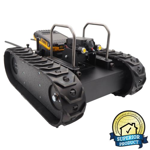
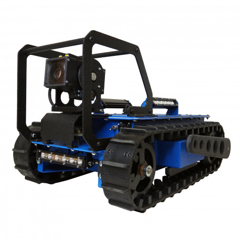
Lastly, there is a tethered inspection robot from SupderDroid Robots. The entire system is waterproof, has a longer runtime and the camer allows for a 360° pan with a -10°/+90° tilt, which allows for a clear visioni. There are two main disadvantages, one being its size and the other the fact that it requires tethering to be able to be controlled. With dimensions of 48cm by 80cm and a height of 40cm (18.9" X 31.2" X 15.7"), it is a bit big to be used in some crawl spaces, which might cause it to get stuck easier. Lastly, the fact that it is tethered means that the cable can also easily be stuck and that the robot requires more precise control.
Old literature
| Paper Title | Reference | Reader |
|---|---|---|
| Mapping and localization module in a mobile robot for insulating building crawl spaces | [34] | Jelmer L |
| A review of locomotion mechanisms of urban search and rescue robot | [35] | Joaquim |
| Variable Geometry Tracked Vehicle, description, model and behavior | [36] | Joaquim |
| Design and basic experiments of a transformable wheel-track robot with self-adaptive mobile mechanism | [37] | Wouter |
| Rough terrain motion planning for actuated, Tracked robots | [38] | Wouter |
| Realization of a Modular Reconfigurable Robot for Rough Terrain | [39] | Wouter |
| Analysis and optimization of geometry of 3D printer part cooling fan duct | [40] | Wouter |
| A Staircase and Slope Accessing Reconfigurable Cleaning Robot and its Validation | [41] | Wouter |
| Dynamics and stability analysis on stairs climbing of wheel–track mobile robot | [42] | Joaquim |
| Research on Dynamics and Stability in the Stairs-climbing of a Tracked Mobile Robot | [43] | Joaquim |
====Mapping and localization module in a mobile robot for insulating building crawl spaces====
This paper describes a possible use case of the system we are trying to develop. According to studies referenced by the authors the crawl spaces in many european buildings can be a key factor in heat loss in houses. Therefore a good solution would be to insulate below floor to increase the energy efficiency of these buildings. However this is a daunting task since it requires to open up the entire floor and applying rolls of insulation. The authors then propose the creation of a robotic vehicle that can autonomously drive around the voids between floors and spray on foam insulation. There already exist human operated forms of this product, however the authors suggest an autonomous vehicle can save time and costs. A big problem with the Simultanious localization and mapping (SLAM) problem in underfloor environments according to the authors is the presence of dust, sand, poor illumination and shadows, this makes the mapping very complex according to the authors.
A proposed way to solve the complex mapping problem is by using both camera and laser vision combined to create accurate maps of the environment. The authors also describe the 3 reference frames of the robot, they consist of the robot frame, the laser frame and the camera frame. The laser provides a distance and with known angles 3d points can be created which can then be transformed into the robot frame. The paper also describes a way of mapping the color data of the camera onto the points
The authors continue to explain how the point clouds generated from different locations can be fit together into a single point cloud with an iterative closest point (ICP) algorithm. The point clouds generated by the laser are too dense for good performance on the ICP algorithm. Therefore the algorithm is divided in 3 steps, point selection, registration and calidation. During point selection the amount of points is drastically reduced, by downsampling and removing floor and ceiling. Registration is done by running an existing ICP algorithm on different rotations of the environment. This ICP algorithm returns a transformation matrix that forms the relation between two poses and one that maximizes an optimization function is considered to be the best. The validation step checks if the proposed solution for alignment of the clouds is considered good enough. Finally the calculation of the pose is made depending on the results of the previous 3 steps.
Lastly, the paper discusses the results of some expirements which show very promising results in building a map of the environment
A review of locomotion mechanisms of urban search and rescue robot
This paper investigates/compiles different locomotion methods for urban search and resque robots. These include:
Tracks
A subgroup of track-based robots are variable geometry tracked (VGT) vehicles. These robots are able to change the shape of the tracks to anything from flat to triangle-shaped, to bend tracks. This is useful to traverse irregular terrain. Some VGT-vehicles which use a single pair of tracks are able to loosen the tension on the track to allow it to adjust its morphology to the terrain (e.g. allow the track to completely cover a half-sphere surface). An example of such a can be seen below.
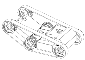
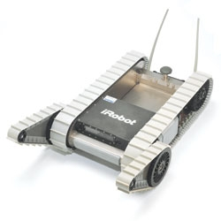
There also exist track based robots which make use of multiple tracks on each side such as the one illustrated below. It is a very robust system making use of its smaller ‘flipper’ to get over higher obstacles. Such an example is seen in the figure below.
Wheels
The paper also describes multiple wheel based systems. One of which is a hybrid of wheel and legs working like some sort of human-pulled rickshaw. This system however is complicated since it will need to continuously map its environment and adjust its actions accordingly.
Furthermore the paper details a wheel-based robot capable of directly grasping a human arm and carrying it to safety.
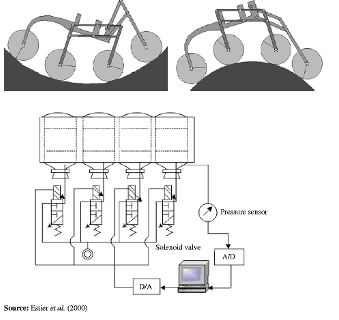
A vehicle using a rover-like configuration as shown below is also discussed. The front wheel makes use of a spring to ensure contact and the middle wheels are mounted on bogies to allow it to passively adhere to the surface. This kind of setup could traverse obstacles as large as 2 times its wheel diameter.
Gap creeping robots
I took the liberty of skipping this since it was mainly focussed on robots purely able to move through pipes, vents etc. which is not applicable for our purposes.
Serpentine robots
The first robot which is explored is a multiple degrees of freedom mechanical arm which is capable of holding small objects with the front and has a small camera attached there also. This being a mechanical arm means it is not truly capable of locomotion but it still has its uses in rescue work which has a fragile and sometimes small environment which a small cross section could help with. The robot is controlled using wires which run throughout the body which are actuated at its base.
Leg based systems
The paper describes a few leg based designs. First of which was created for rescue work after the Chernobyl disaster. This robot-like design spans almost 1 metre and is able to climb vertically using the suction cups on its 8 legs. While doing so, it is able to carry up to 25 kg of load. It can also handle transitions between horizontal and vertical terrain. Furthermore it is able to traverse concave surfaces with a minimum radius of 0.5 metres.
Conclusion
This paper concludes by evaluating all prior robots and their real life application in search and rescue work. This however is not relevant for autonomous crawl space scanning. Except it may indicate why none of the prior robots would be suitable for search and rescue work due to the unstructured environment and the limitations of its autonomous workings.
====Variable Geometry Tracked Vehicle, description, model and behavior====
This paper presents a prototype of an unmanned, grounded, variable geometry tracked vehicle (VGTV) called B2P2. The remote controlled vehicle was designed to venture through unstructured environments with rough terrain. The robot is able to adapt its shape to increase its clearing capabilities. Different from traditional tracked vehicles the tracks are actively controlled which allows it more easily clear some obstacles.
The paper starts off with stating that robots capable of traversing dangerous environments are useful. Particularly ones which are able to clear a wide variety of obstacles. It states that to pass through small passages a modest form factor would be preferable. B2P2 is a tracked vehicle making use of an actuated chassis as seen in a prior image.
The paper states that the localization of the centre of gravity is useful for overcoming obstacles. However, since the shape of the robot isn’t fixed, a model of the robot is a necessity to find it as a function of its actuators. Furthermore the paper explains how the robot geometry is controlled which consists of the angle at the middle and the tension-keeping actuator between the middle and last axes. These are both explained using a closed-loop control diagram.
Approaching the end of the paper multiple obstacles are discussed and the associated clearing strategy. I would suggest skimming through the paper to view these as they use multiple images. To keep it brief they discuss how to clear: a curb, staircase, and a bumper. The takeaway is that being able to un-tension the track allows it to have more control over its centre of gravity and allows increasing friction on protruding ground elements (avoiding the typical seesaw-like motion associated with more rigid track-based vehicles).
In my own opinion these obstacles highlight 2 problems:
- The desired tension on the tracks is extremely situationally dependent. There are 3 situations in which it could be desirable to lower the tension, first is if it allows the robot to avoid flipping over by controlling its centre of gravity (seen in the curb example). Secondly it could allow the robot to more smoothly traverse pointy obstacles (e.g. stairs such as shown in the example). Thirdly, having less tension in the tracks could allow the robot to increase traction by increasing its contact area with the ground. This context-dependent tension requirement to me makes it seem that fully autonomous control is a complex problem which most likely falls outside of the scope of our application and this course.
- The second problem is that releasing tension could allow the tracks to derail. This problem however could be partially remedied by adding some guide rails/wheels on the front and back. This would confine the problem to only the middle wheels.
The last thing I would want to note is that if the sensor to map the room is attached to the second axis, it would be possible to alter the sensor’s altitude to create different viewpoints.
====Design and basic experiments of a transformable wheel-track robot with self-adaptive mobile mechanism====
This paper shows the design process of one fully mechanical track powered by one servo. The mechanism is quite complicated but the design process shows a lot of information on designing for rough terrain. This paper is focused on efficiency so less motors are needed, which is important while the robot can then be smaller.
The robot has an adaptive drive system which when moving over rough terrain its mobile mechanism gets constraint force information directly instead of using sensors. This information can be used to move efficiently by changing locomotion mode.
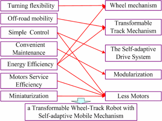
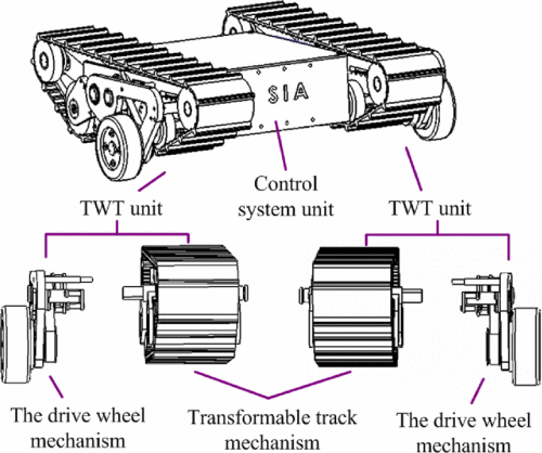
Basically it is composed of a transformable track and a drive wheel mechanism. With the following modes:
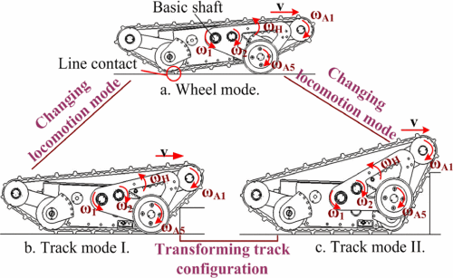
After this they mainly showed the mechanical details on how their design works. With formulas and CAD models.
They used three experiments Moving on the Even and Uneven Road Overcoming Obstacle by Track Overcoming Obstacle with Different Heights by Wheels It was able to overcome obstacles of 120 mm height while having itself a max height of 146 mm.
Conclusion
Basic experiments have proven that the robot is adaptable over different terrain. The full mechanical design shows promise for our work and goals.
Rough terrain motion planning for actuated, Tracked robots
This paper proposes a two step path planning for moving over rough terrain. Firstly consider the robot’s operating limits for a quick initial path. Refine segments that are identified to be through rough areas.
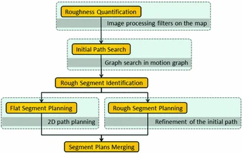
The terrain is seen by using a camera with image processing. Something cannot be overcome if the hill is too high or inclination is too steep. The first path search uses a roughness quantification to prefer less risky routes and is mainly based on different weights. The more detailed planning is done by splitting paths into segments with flat spots and rough spots. After this it uses environmental risk with system safety in a formula to give it a weight.
Further the paper gives a roadmap (based on A*) and RRT* planner.
Realization of a Modular Reconfigurable Robot for Rough Terrain
This paper has a robot for rough terrain to use multiple modular reconfigurable robots. Basically a robot with multiple modules that can be disconnected from each other. Using different modules can make the robot do different tasks better. It looks like this:

It can be used for steps like this:
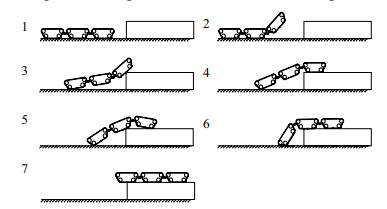
The joint between the robots can move and rotate in basically all directions which makes it able to traverse a lot of terrains.

====Analysis and optimization of geometry of 3D printer part cooling fan duct====
This paper researched fan ducts for 3D printers and how to optimise it for maximum airflow. Of Course we are not making a 3D printer but the principles of airflow are mostly the same. The paper analysis it based on inlet, outlet and throat length. And concludes optimised inlet angle of 40 degrees, outlet angle of 20 degrees with a 3 mm throat length. It optimised the fan with 23% more airflow.
Important is that this fan used in this research was 27 mm, which seems feasible for an as small as possible crawler.
Here are the results processed in ANSYS 2021 R1 cfd. First the outlet was done then throat length and finally inlet, because outlet has the biggest impact based on their prior research.

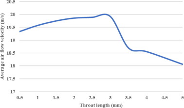

====A Staircase and Slope Accessing Reconfigurable Cleaning Robot and its Validation | IEEE Journals & Magazine====
This mechanism is made for cleaning robots but could also be used for a guide robot. It basically drives on 4 wheels with each wheel having a motor. The front and back can go linear straight up and down. This makes it more stable to ascend for robots with large dimensions because it can stay mostly straight up, and it can descend staircases as shown in the figure below:
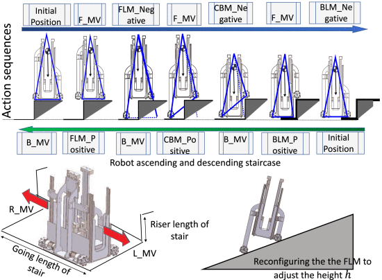
The locomotion mechanism is holonomic, so it can move in any direction. The robot however descends backwards. So basically when moving up or down it has the same rotation in comparison to the floor. As the front is for moving up and the back is for moving down.
All Hardware and details about the mechanical design is given.
During the experiments the robot was very stable. It has still to improve mainly with a feedback controller. They however did not give the velocity of climbing stairs or slopes.
====Dynamics and stability analysis on stairs climbing of wheel–track mobile robot====
This robot is capable of switching between more compact wheel-based locomotion and track-based locomotion (intended for stair climbing). The robot is depicted in the figure below. As seen it is quite a complicated mechanism.
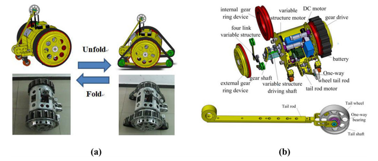
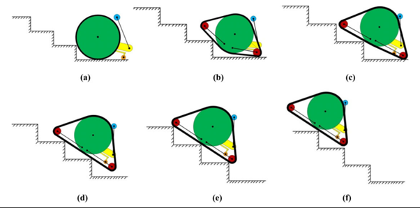
The wheeled-mode allows it to safe battery while maintaining the advantage of rough-surface/stair traversal capabilities of tracked vehicles. The figure to the right shows its stair-climbing capabilities. The paper also goes in detail about how the mechanisms interact and their purposes. I think the largest problem with this design is actually the expansion of the track itself. The robot in the paper solves this by creating a spring-based track which can also be seen in a figure to the right.

This seems to be quite a finicky part which not only has to work smoothly but will also require special care in how it is driven. The robot in the paper makes use of the re component which is driven by the internal teeth. It has a sloped groove over its surface which I assume will jam the spring to increase friction and allowing the tracks to be driven.
The finishing note on the mechanical design is the tail rod, the purpose of which is to allow the robot some extra stability when folded down which is seen in action in some actual photos which show the prototype climbing a staircase.
The rest of the paper goes in-depth about dynamic analyses of the kinematic model and how the robot is controlled.
Research on Dynamics and Stability in the Stairs-climbing of a Tracked Mobile Robot
This paper goes over the dynamics of a simple tracked vehicle and it’s stability. The paper’s most applicable part according to me (for our objective of creating a prototype) is the 3 conditions they set for a robot to be able to climb stairs:
The geometric condition
The robot is capable of touching the stair edge and drive over the edge.
The traction condition
The motor should have enough traction on the track to drive it.
The friction condition
The robot should not slide on the stairs.
The paper goes very in-depth in how to evaluate stability but this would mostly fall outside of the scope of this assignment.
- ↑ What Guide Dogs Do - How Guide Dogs Work | HowStuffWorks
- ↑ What A Guide Dog Is Trained To Do | Guide Dogs
- ↑ How Do Guide Dogs for the Blind Work? Everything You need to Know (mypetneedsthat.com)
- ↑ Z. Kowalczuk and T. Merta, "Modelling an accelerometer for robot position estimation," 2014 19th International Conference on Methods and Models in Automation and Robotics (MMAR), Miedzyzdroje, Poland, 2014, pp. 909-914, doi: 10.1109/MMAR.2014.6957478.
- ↑ Woodman, O. J. (2007). An introduction to inertial navigation (No. UCAM-CL-TR-696). University of Cambridge, Computer Laboratory.
- ↑ T. Lee, J. Shin and D. Cho, "Position estimation for mobile robot using in-plane 3-axis IMU and active beacon," 2009 IEEE International Symposium on Industrial Electronics, Seoul, Korea (South), 2009, pp. 1956-1961, doi: 10.1109/ISIE.2009.5214363.
- ↑ Athani, V. V. (1997). Stepper motors: fundamentals, applications and design. New Age International.
- ↑ https://arxiv.org/pdf/1903.01067v2.pdf
- ↑ http://www.roboticsproceedings.org/rss09/p37.pdf
- ↑ https://www.robots.ox.ac.uk/~mobile/drs/Papers/2022RAL_zhang.pdf
- ↑ Luis C. Básaca-PreciadoOleg Yu. SergiyenkoJulio C. Rodríguez-QuinonezXochitl GarcíaVera V. TyrsaMoises Rivas-LopezDaniel Hernandez-BalbuenaPaolo MercorelliMikhail PodrygaloAlexander GurkoIrina TabakovaOleg Starostenko (2013), Optical 3D laser measurement system for navigation of autonomous mobile robot, https://www.sciencedirect.com/science/article/pii/S0143816613002480
- ↑ Dorit Borrmann, Andreas Nüchter, Marija Ðakulović, Ivan Maurović, Ivan Petrović, Dinko Osmanković, Jasmin Velagić, A mobile robot based system for fully automated thermal 3D mapping (2014), https://www.sciencedirect.com/science/article/pii/S1474034614000408
- ↑ Zhiliang Ma, Shilong Liu, 2018, A review of 3D reconstruction techniques in civil engineering and their applications (2014), https://www.sciencedirect.com/science/article/pii/S1474034617304275?casa_token=Bv6W7b-GeUAAAAAA:nGuyojclQld2SMnIeHougCByarFJX7eu049kMp_IWrnU5e8ljX9RMao-U4vs6cB3nREk8JP3qIA
- ↑ Juan Li, Xiang He, Jia L, 2D LiDAR and camera fusion in 3D modeling of indoor environment (2015), https://ieeexplore.ieee.org/document/7443100
- ↑ https://www.mdpi.com/2072-4292/14/12/2835
- ↑ Francesco Amigoni, Vincenzo Caglioti, An information-based exploration strategy for environment mapping with mobile robots, Robotics and Autonomous Systems, Volume 58, Issue 5, 2010, Pages 684-699, ISSN 0921-8890, https://doi.org/10.1016/j.robot.2009.11.005. (https://www.sciencedirect.com/science/article/pii/S0921889009002024)
- ↑ M. Betke and L. Gurvits, "Mobile robot localization using landmarks," in IEEE Transactions on Robotics and Automation, vol. 13, no. 2, pp. 251-263, April 1997, doi: 10.1109/70.563647.
- ↑ https://link.springer.com/article/10.1007/s40815-020-01046-x?utm_source=getftr&utm_medium=getftr&utm_campaign=getftr_pilot
- ↑ https://ieeexplore.ieee.org/document/9536077
- ↑ Bellotti, F., Berta, R., De Gloria, A., & Margarone, M. (2006). Guiding visually impaired people in the exhibition. Mobile Guide, 6, 1-6.
- ↑ João Guerreiro, Daisuke Sato, Saki Asakawa, Huixu Dong, Kris M. Kitani, Chieko Asakawa, Designing and Evaluating an Autonomous Navigation Robot for Blind People (2019), https://dl.acm.org/doi/pdf/10.1145/3308561.3353771
- ↑ Asraa Al-Wazzan , Farah Al-Ali, Rawan Al-Farhan , Mohammed El-Abd, Tour-Guide Robot (2016), https://ieeexplore.ieee.org/stamp/stamp.jsp?tp=&arnumber=7462397
- ↑ Debajyoti Bosea, Karthi Mohanb, Meera CSc, Monika Yadavc and Devender K. Saini, Review of Autonomous Campus and Tour Guiding Robots with Navigation Techniques (2021), https://www.tandfonline.com/doi/epdf/10.1080/14484846.2021.2023266?needAccess=true&role=button
- ↑ The Fuzzy Control Approach for a Quadruped Robot Guide Dog | SpringerLink
- ↑ Design of a Portable Indoor Guide Robot for Blind People | IEEE Conference Publication | IEEE Xplore
- ↑ Design of a Portable Indoor Guide Robot for Blind People | IEEE Conference Publication | IEEE Xplore
- ↑ Gromicko, N. (n.d.). Crawlspace Hazards and Inspection. InterNACHI®. https://www.nachi.org/crawlspace-hazards-inspection.htm
- ↑ Cink, A. (2022, 5 april). Crawl Bots for Home Inspectors: Are they worth the investment? InspectorPro Insurance. https://www.inspectorproinsurance.com/technology/crawl-bots/
- ↑ Crawl Pros. (2021, 12 March). The Low Down: Crawl Spaces vs. Basements 2022. https://crawlpros.com/the-low-down-crawl-spaces-vs-basements/
- ↑ G. (2022, 19 December). Kruipruimte uitdiepen (10 - 70 cm). De Kruipruimte Specialist. https://de-kruipruimte-specialist.nl/kruipruimte-uitdiepen/
- ↑ https://www.inspectioncrawlers.com/
- ↑ https://www.superdroidrobots.com/store/industries/pest-control/product=2729
- ↑ https://www.superdroidrobots.com/store/industries/pest-control/product=2452
- ↑ Mapping and localization module in a mobile robot for insulating building crawl spaces. (z.d.). https://www.sciencedirect.com/science/article/pii/S0926580517306726
- ↑ Wang, Z. and Gu, H. (2007), "A review of locomotion mechanisms of urban search and rescue robot", Industrial Robot, Vol. 34 No. 5, pp. 400-411. https://doi.org/10.1108/01439910710774403
- ↑ Jean-Luc Paillat, Philippe Lucidarme, Laurent Hardouin. Variable Geometry Tracked Vehicle, description, model and behavior. Mecatronics, 2008, Le Grand Bornand, France. pp.21-23. ffhal-03430328
- ↑ Design and basic experiments of a transformable wheel-track robot with self-adaptive mobile mechanism | IEEE Conference Publication | IEEE Xplore
- ↑ Rough Terrain Motion Planning for Actuated, Tracked Robots | SpringerLink
- ↑ IEEE Xplore Full-Text PDF:
- ↑ Analysis and optimization of geometry of 3D printer part cooling fan duct - ScienceDirect
- ↑ https://ieeexplore.ieee.org/document/9714003
- ↑ 42.0 42.1 42.2 42.3 Gao, X., Cui, D., Guo, W., Mu, Y., & Li, B. (2017). Dynamics and stability analysis on stairs climbing of wheel–track mobile robot. International Journal of Advanced Robotic Systems, 14(4), 1729881417720783.
- ↑ Tao, W., Ou, Y., & Feng, H. (2012). Research on Dynamics and Stability in the Stairs-climbing of a Tracked Mobile Robot. International Journal of Advanced Robotic Systems, 9(4), 146.
- ↑ Paillat, Jean-Luc & Com, Jlpaillat@gmail & Lucidarme, Philippe & Hardouin, Laurent. (2008). Variable Geometry Tracked Vehicle (VGTV) prototype: conception, capability and problems.
- ↑ Paillat, Jean-Luc & Com, Jlpaillat@gmail & Lucidarme, Philippe & Hardouin, Laurent. (2008). Variable Geometry Tracked Vehicle (VGTV) prototype: conception, capability and problems.
- ↑ Wang, Z. and Gu, H. (2007), "A review of locomotion mechanisms of urban search and rescue robot", Industrial Robot, Vol. 34 No. 5, pp. 400-411. https://doi.org/10.1108/01439910710774403
- ↑ Design and basic experiments of a transformable wheel-track robot with self-adaptive mobile mechanism | IEEE Conference Publication | IEEE Xplore
- ↑ Design and basic experiments of a transformable wheel-track robot with self-adaptive mobile mechanism | IEEE Conference Publication | IEEE Xplore
- ↑ Design and basic experiments of a transformable wheel-track robot with self-adaptive mobile mechanism | IEEE Conference Publication | IEEE Xplore
- ↑ Rough Terrain Motion Planning for Actuated, Tracked Robots | SpringerLink
- ↑ IEEE Xplore Full-Text PDF:
- ↑ IEEE Xplore Full-Text PDF:
- ↑ IEEE Xplore Full-Text PDF:
- ↑ Analysis and optimization of geometry of 3D printer part cooling fan duct - ScienceDirect
- ↑ Analysis and optimization of geometry of 3D printer part cooling fan duct - ScienceDirect
- ↑ Analysis and optimization of geometry of 3D printer part cooling fan duct - ScienceDirect
- ↑ S-Sacrr: A Staircase and Slope Accessing Reconfigurable Cleaning Robot and its Validation | IEEE Journals & Magazine | IEEE Xplore