Mobile Robot Control 2020 Group 8: Difference between revisions
| Line 82: | Line 82: | ||
<!-- These enters are placed on purpose for proper allignment! --> | <!-- These enters are placed on purpose for proper allignment! --> | ||
= Design document= | = Design document= | ||
Revision as of 20:33, 15 May 2020
Group information
Group Members
| Name | Student Number |
|---|---|
| J.J.W. Bevers | 0904589 |
| J. Fölker | 0952554 |
| B.R. Herremans | 0970880 |
| L.D. Nijland | 0958546 |
| A.J.C. Tiemessen | 1026782 |
| A.H.J. Waldus | 0946642 |
Meeting Summaries
| Date | Content |
|---|---|
| 29-04-2020 | This was an introductory meeting during which the group met with the tutor, Wouter Houtman. We briefly discussed with him what he expected of us and how we were planning to make progression. Also, we discussed the contents of the design document. We had a general discussion about the expectations of the course and the two challenges. As a group, we agreed to have at least two meetings per week, one with our tutor to discuss progression and to ask questions and one without him. We agreed that every group member should watch the lectures and make the tutorials. If one does not do so, he will fall behind and will not be able to help the group progress. Moreover, since none of the group members has experience with C++, every group member is advised to practice in the programming language. For next meeting, every group member should, apart from watching the lectures and finishing the tutorials, get some inspiration for the design document. Sources of inspiration are the wiki pages of groups of previous years and the general wiki page with the description of the challenges. |
| 01-05-2020 | In order to remember what is agreed upon during the meeting, we assigned someone to take minutes. Next time, he will lead the meeting to improve the structure and someone else will be taking the minutes. A role division scheme will be made. During this meeting, we discussed the five items that should be included in the design document. First, we agreed that we should first focus on the requirements and specification. By further specifying the requirements and specifications, functions will follow. Once the functions are known, they can be divided among the components of PICO. The components will on its turn be included in the software architecture with the corresponding interfaces. We decided to roughly follow the scheme of lecture 2.1 for the requirements and specification. Next, we divided the tasks. Two people will work on the requirements and specifications, two on the functions and two on the interfaces and components. Since the deadline for the design document is 04-05-2020, we set a deadline on 03-05-2020 for a first draft of the different tasks. This gives us sufficient time to process feedback from others and finalize the design document. |
| 03-05-2020 | This meeting was planned as a follow up on the tasks assigned in the previous meeting. First, some general agreements were made. It was decided to create an OneDrive folder so that it would become easier to share and store documents. Also, the minute taker was made responsible to update this meeting log on our Wiki page. Afterwards, each subgroup shortly explained their work. After this brief explanation, some possible improvements were discussed and noted in the minutes, so that they can be implemented. The main points of improvement were focused on small adjustments for each part to be coherent with the other parts. At last, we looked at how to continue towards the next meeting planned on Thursday. The first priority would be to finish the Design Document. It was decided to finish it today so that it can be checked and delivered on Monday before 5 pm. After that deadline, all members would further investigate Tutorial 12, since this would help to create an understanding of a simple software implementation. Besides that, the same subgroups were appointed to work out some of the capabilities as formed in the Design Document. The expected outcome of this task would be a general approach (or possible libraries/algorithms to use) and possibly a piece of code. |
| 07-05-2020 | This meeting was used to receive feedback from our tutor on the design document, and to discuss our approach for the escape room challenge. One of the feedback points that was received was that the design document could have been more explicit. We got the recommendation to continue to update the design document, since this will make the programming part easier. After this we discussed the algorithms we are working on, and what the advantages and disadvantages of each algorithm are. In the end, we divided the work for next meeting (08-05) in three sub assignments. The first duo would work on the project structure and corner detection, while another duo would work on the potential field algorithm. The last duo is going to investigate and program the corridor exit procedure. The goal for the next meeting is that the structure is finished and that the individual parts can be implemented into one system, since integral testing will probably uncover quite a few problems between the components. |
| 08-05-2020 | During this meeting the progress of the implementation of the potential field algorithm, an algorithm able to identify the target at the exit of the room, and the investigated approaches of driving straight through the exit corridor are discussed. The rejective field gradient has been implemented successfully and movement in (x,y,theta) can be initiated according to this gradient vector. Potential field is likely to be able to drive through a corridor if the execution rate is sufficiently high. A split & merge approach for detecting wall features is investigated mathematically using Matlab. Recursive fitting is used to fit lines to measurement points from the laser range finder corresponding to a single feature. Finally the strategy for the room challenge and hospital challenge has been further elaborated and the structure corresponding to the approach for the room challenge has been implemented. Goal for next meeting is to compare the split & merge approach with the corner detection algorithm, to see which one is more efficient. Furthermore the potential field algorithm will be further implemented to include the attractive field. Finally the implementation in C++ for the room challenge will be continued and possibility of visualizing gradient vectors and identified corners will be investigated. |
| 11-05-2020 | In this meeting, we met with our new tutor, Jordy Senden. We got some more feedback on our design document: i) the graph of stakeholders and different types of requirements is good, but the connections can be worked out further and some requirements are still missing a specified value (e.g. min. speed), and ii) it is questionable whether the planning state of the finite state machine is needed (or is planning going to happen in another state simultaneously with other tasks). Moreover, we asked the tutor some questions regarding visualization, our strategy for the escape room challenge and programming in c++. After that, we shortly introduced our current software to the tutor: part 1 that (mainly) applies the potential field algorithm and part 2 that (mainly) applies (a sort of) split and merge segmentation. Finally, we further discussed what we were going to work on up until the escape room challenge which is in two days. Regarding part 1 (potential field algorithm), we decided to start using odometry data as a means of updating the target location (i.e. the corridor) for cases where part 2 fails to produce a new target location. A lot of debugging still needs to be done to get part 2 working as expected, therefore we decided to compare MATLAB and c++ results to see where it goes wrong. Moreover, part 2 will be tested more thoroughly in MATLAB, i.e. using more data obtained from the PICO simulator, and we plan on adding a more thorough preprocessing on the LRF data at the beginning of the part 2 software to increase robustness. |
| 12-05-2020 | During this meeting, we discussed our results in order to define the last tasks for the Escape Room Challenge. Our potential field algorithm ensures that PICO keeps track of the odometry data in order to identify it's current position relative to the target. The split and merge algorithm is now able to locate the target at the exit of the room and at the end of the corridor. However, this algorithm has some robustness issues which need to be fixed. Next to this, the visualization of PICO's perception of the surrounding is implemented. Now, both algorithms need to be combined into a single working program, which then can be tested and finally used for the Escape Room Challenge. |
| 15-05-2020 | This was the first meeting after the successful Escape Room Competition, which we finished in first place! During this meeting we discussed how we plan to continue. First we agreed that we want to update our Wiki. In order to do so, we are going to improve the design document. We have already copied the content of the design document onto our Wiki page, but we are going to implement previously received feedback. Next, we want to elaborate upon the software used for the Escape Room Competition. We are going to explain the split & merge detection method and the potential field algorithm in more detail. While working towards our final version of the software, visualization has been used to check whether the algorithms were implemented correctly and for debugging. However, we intentionally left this out during the Escape Room Competition. Since we do want to show how this has been used, two videos will be added to the Wiki page: one of how PICO behaved during the Escape Room Competition and one of the corresponding visualization of our software. Moreover, we will prepare for next meeting by exploring three different topics relevant for the Hospital competition. We will investigate the posibilities for localization & mapping, motion control & obstacle avoidance and path planning. |
Course description
Introduction
As is proven during the current situation concerning the COVID-19 pandemic, our healthcare system is of high importance. However, there are shortcomings for which an efficient solution is required. At the time, the hospitals are occupied by many patients. Therefore, doctors and nurses have limited time for human-to-human contact with patients. By automating simple tasks, doctors and nurses have more time for contact with patients. An option is to use an autonomous embedded robot to assist in the everyday tasks such as getting medicine, moving blood bags or syringes and getting food and drinks. During this course, software for such an autonomous robot is developed. The goal is to complete two different simulated challenges: the Escape Room Challenge and the Hospital Challenge.
PICO
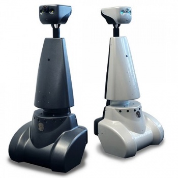
The mobile robot used is called PICO and is shown in Figure 1. PICO consists of multiple components. Since this year's edition of the course will only make use of simulations of PICO, and not implementation of the software on the actual robot, only the relevant components for simulations are briefly explained. In order to actuate, PICO uses Omni-wheels which allow 2D translation and rotation. These Omni-wheels thus provide PICO with a holonomic base. A Laser Range Finder (LRF) is used by PICO to scan its surroundings. Furthermore, Odometer wheel encoders are used to keep track of rotations and movements.
Escape Room Challenge
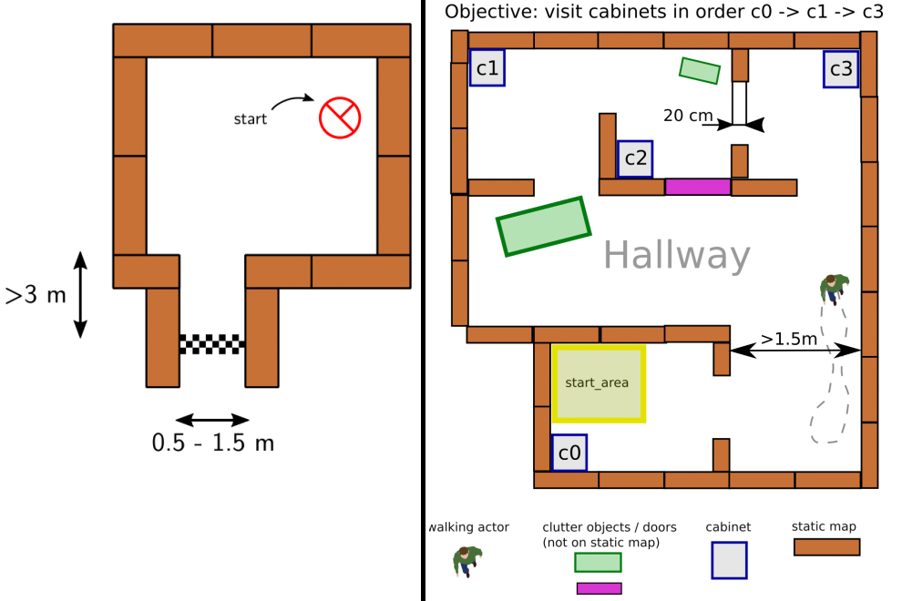
The goal of this challenge is to navigate PICO, through a corridor, out of a room with unknown dimensions without bumping into walls. An example of an environenment map that might be encountered during this challenge is shown on the left side of Figure 2. PICO has an unknown initial position within this room. Thus first, PICO needs to detect and recognize the exit. When the exit is found, PICO has to exit the room as fast as possible by moving through the corridor. The challenge is finished when the rear wheels of PICO cross the finish line entirely. In the section execution of the Escape Room Challenge, the approach is explained in more detail. Here, the algorithms used and its implementations are explained. Moreover, the results of the challenge are shown and discussed.
Hospital Challenge
This challenge represents an example of the application of an autonomous robot in a more realistic environment. In this challenge, PICO has to operate in a hospital environment. The environment will consists of multiple rooms, a hallway and an unknown number of static- and dynamic objects. In the rooms, cabinets are present that contain medicine. In this challenge, PICO will need to recognize its initial position in a provided environment first. Next, PICO has to plan a path to various cabinets in a predefined order, representing PICO collecting and delivering medicine. When executing this path, PICO needs to prevent collisions with walls and static- and dynamic objects. An example of such an environment is shown on the right side of Figure 2.
Design document
In preparation of the two challenges, a design document is produced. In this design document, requirements, specification, functions, components and interfaces that the describe the initial design idea are discussed. It is chosen to produce a generic design document applicable to both challenges. However, since the Escape Room Challenge will be the first challenge to overcome, certain topics, such as functions, might be designed more specifically for this challenge.
Requirements and Specifications
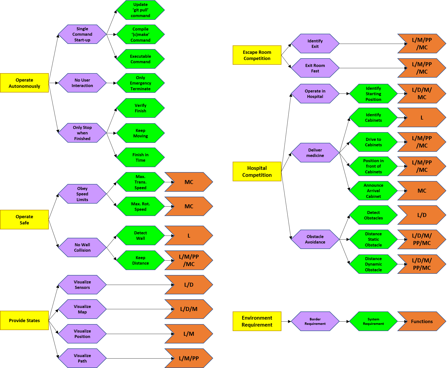
A distinction is made between general and competition specific requirements. Three stakeholders are considered: the hospital employees, patients and software engineers. In ascending order, the requirements are subdivided into environment requirements, border requirements, system requirements and function types. Five functions types are introduced: Localization(L), Detection(D), Mapping(M), Path Planning(PP) and Motion Control(MC). These are elaborated in the next section. The requirements are shown in Figure 3 and elaborated below. Note the legend located bottom right. First, the five environment requirements will be discussed in more detail.
- PICO should operate autonomously: No interaction is allowed, unless an emergency stop is needed. To start the software, the ’git pull’ command is used to update, the ’cmake’ and ’make’ commands are used for compiling and one executable is used to start execution.
- PICO can only stop executing when its task is finished: Therefore it must be able to verify when it is finished. Also, PICO cannot be stationary for 30 consecutive seconds and the task must be finished in time. PICO should operate safely. In order to do so, it must obey speed limits. A maximum transnational and rotational speed of 0.5 m/s and 1.2 rad/s, respectively, are set.
- PICO can not bump into walls: Therefore, PICO should be able to detect walls and keep a certain distance. PICO should provide information on its state. Therefore, PICO should visualize its sensor data, produce and visualize a map and its current position and finally visualize its produced path.
- PICO should finish the Escape Room Competition: To succeed, PICO must be able to identify the exit and it should exit as fast as possible. A strategy is explained in the next section.
- PICO should finish the Hospital Competition: PICO should deliver medicine. Therefore, PICO must recognize cabinets, drive to them, position in front of them facing towards them and afterwards produce a sound signal. PICO should operate in the hospital environment. Therefore it must recognize its (initial) position in the provided map. Finally, PICO should not bump into static or dynamic objects. Thus PICO should detect an object within a 10 meter range and the distance between PICO and a static or dynamic object must be at least 0.2 m and 0.5 m respectively.
The hospital employees are involved in the first, second and fifth requirement, the patients in the second and fifth and the software engineers in the first, third and fourth.
Finite State Machine
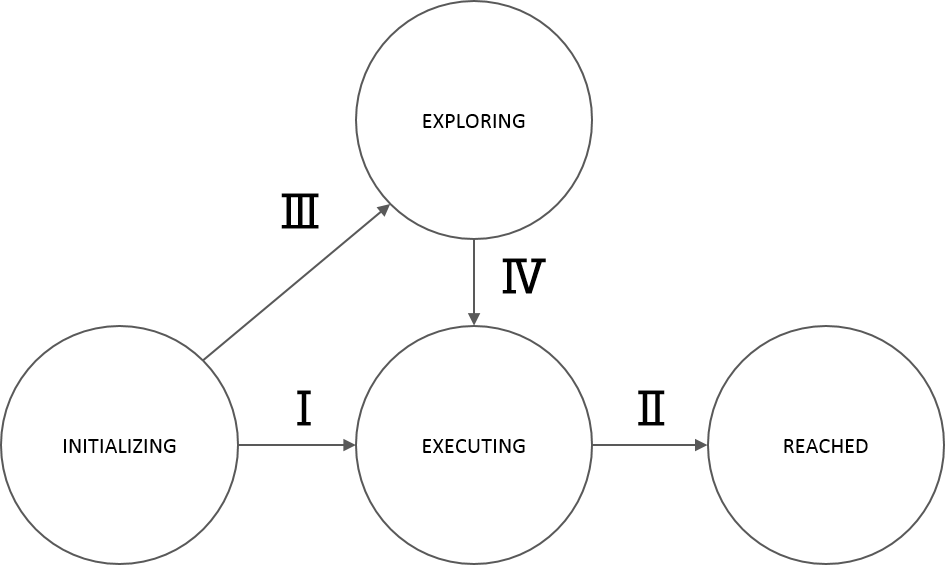
The finite state machine displayed in figure 4 depicts the designed behavior of PICO, allowing it to complete the two challenges. The states are:
- State I - Initializing: PICO performs an initial scan of it’s surroundings and maps this data to find its position on the map. It is possible that insufficient information has been gathered to do this when, for instance, all objects are out of reach of the laser range finder.
- State II - Exploring: An exploration algorithm such as a potential field algorithm or a rapidly expanding random tree algorithm is used to explore the environment further. When PICO’s position within the map is known and the exploration algorithm has been executed for T seconds, the transition to State III occurs.
- State III - Planning: After PICO has localized itself on the map, enough information has been gathered to compute a path towards a target. An algorithm is used to compute a state trajectory,that is then translated into control actions.
- State IV - Executing: During this state a control loop is executed which controls PICO towards the reference coordinates (x,y) by measuring position and actuating velocities. When PICO runs into an unexpected close proximity object, the state is transferred to State V. When PICO runs into an unexpected distant proximity object, the state is transferred to State III, such that a new path can be planned before PICO arrives at this object.
- State V - Recover: During the recover state, PICO has encountered a close proximity object which it did not expect. PICO then immediately stops and when completely stopped, it transits to State II, such that the exploration algorithm can move PICO away from this unexpected object for T seconds. The loop (State II, State III, State IV, State V) can be executed repeatedly and can be counted, such that T increases when more loops are encountered.
- State VI - Reached: After the path execution has been finished and PICO has reached the end of the path, PICO stops moving as it has reached its target location.
Software Architecture
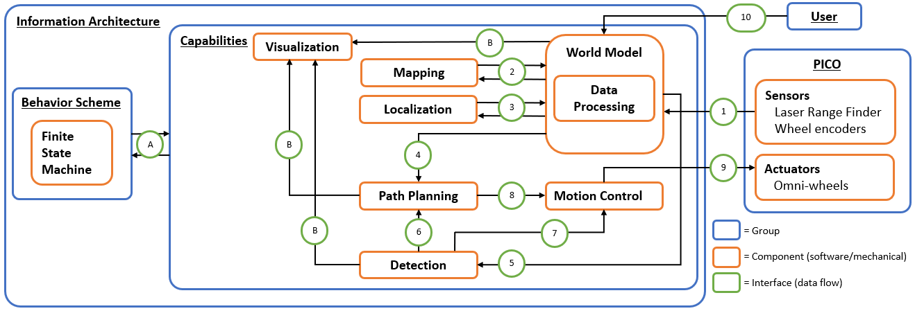
The proposed information architecture is depicted in Figure 5. It shows a generic approach, so note that a specific challenge may require additional functionalities and interfaces. Between the software and mechanical components, information is shared via interfaces marked in green and labeled with an arbitrary number or letter. These interfaces dictate what information is set by which component and what information is shared, and among which components. In the central section, this schematic overview visualizes what capabilities are intended to be embedded in the software. Firstly, interface 10 represents the data received from the user, which may include a JSON file with a map and markers, depending on the challenge. On the right, interface 1 between PICO (including the provided software layer) and the designed software shows the incoming sensor data, i.e. structs with distance data from the Laser Range Finder (LRF) and odometry data based onthe omni-wheel encoders. This data is (possibly) processed and used to map PICO’s environment(mapping), to estimate PICO’s position and orientation (localization), and to detect static/dynamic obstacles (detection), via interfaces 2, 3 and 5. This knowledge is stored in the world model,serving as a central data-base. Via interface 4, a combination of the current map, PICO’s poseand the current (user-provided) destination is sent, to plan an adequate path. This path is sent over interface 8, in the form of reference data for the (x,y,θ)-coordinates. The motion controlcomponent will then ensure that PICO follows this path by sending velocity inputs over interface 9. Simultaneously, the detection monitors any static/dynamics obstacles on the current path online. If this is the case,interfaces 6 and 7 serve to feed this knowledge back to either the path planning component to adjust the path or directly to motion control to make a stop. On the left, interface A between the behavior scheme and the capabilities shows that the high-level finite state machine manages what functionality is to be executed and when.Interfaces B represent the data that is chosen to be visualized to support the design process, i.e. the visualization serves as a form of feedback for the designer. The information that is visualized depends heavily on the design choices later on in the process and, therefore, this will not be explained further.
Implementation The components described above are intended to be explicitly embedded in the code through the use of classes. The functionality that belongs to a certain component will then be implemented as a method of that specific class. At this stage of the design process, the specific algorithms/methodsthat will be used for the functionalities are not set, but some possibilities will be mentioned here. Simultaneous mapping and localization (SLAM) algorithms, based on Kalman filters or particle filters, could be used for the mapping and localization components. Moreover, for path planning,Dijkstra’s algorithm, the A* algorithm or the rapidly-exploring random tree algorithm can be used.For motion control, standard PI(D) control, possible with feedforward, can be used to track the reference trajectory corresponding to the computed path. Additionally, for detection, artificial potential fields can be used to stay clear from obstacles.
Execution of the Escape Room Challenge
Deliverables
Design Document
In the design document, a generic approach for the Escape Room Competition and the Hospital Competition is introduced. Requirements are proposed, which are clarified by means of specifications. Based on these, a finite state machine is designed. In each state, groups of functions are proposed. This functionality is, in turn, structured in an information architecture which covers the components and the interfaces. Undoubtedly, throughout the remainder of the course, this document needs to be updated, but its current content functions more as a guideline. Since the Escape Room Competition is the first challenge, functional specifics may be more focused towards this goal. And because software design is use-case dependent, for the Hospital competition the current approach will need to be adapted and improved. The design document deliverable can be found here.