Embedded Motion Control 2018 Group 4: Difference between revisions
| Line 279: | Line 279: | ||
== State Machines == | == State Machines == | ||
For the hospital challenge, discrete (state) control will be required. Therefore, these following two state machines have been designed for the two parts of the challenge: mapping the hospital and finding the object. | For the hospital challenge, discrete (state) control will be required. Therefore, these following two state machines have been designed for the two parts of the challenge: mapping the hospital and finding the object. | ||
[[File:State_machine1.JPG|thumb|center|900px|Figure 2: State machine: mapping hospital]] | [[File:State_machine1.JPG|thumb|center|900px|Figure 2: State machine: mapping hospital]] | ||
Revision as of 16:44, 4 June 2018
Group members
| TU/e Number | Name | |
|---|---|---|
| 1032743 | Shuyang (S.) An | s.an@student.tue.nl |
| 0890579 | Leontine (L.I.M.) Aarnoudse | l.i.m.aarnoudse@student.tue.nl |
| 0892629 | Sander (A.J.M.) Arts | a.j.m.arts@student.tue.nl |
| 1286560 | Pranjal (P.) Biswas | p.biswas@student.tue.nl |
| 0774811 | Koen (K.J.A.) Scheres | k.j.a.scheres@student.tue.nl |
| 0859466 | Erik (M.E.W.) Vos De Wael | m.e.w.vos.de.wael@student.tue.nl |
Files
File:EMC Group4 Initial Design.pdf
Initial Design
Goal
The main goal of the project is to enable PICO to autonomously map a given room and subsequently determine and execute a trajectory to leave this room. For the initial Escape Room Competition, the predefined task is completed once the finish line at the end of the corridor is crossed. For the Hospital Room Competition, the goal is to map all rooms situated in the complex, after which the robot returns to a given position from where it must be able to identify a placed object in order to position itself next to it. However, both competitions include several constraints:
- The robot must complete the task without bumping into any walls.
- The individual tasks must be completed within five minutes.
- The robot should not stand still for more than 30 seconds during the execution of each of the tasks.
Plan
Escape Room Competition
1. Initially, PICO should make a 360° turn once, to gather information about the surrounding environment.
2. It should act accordingly depending upon the initial data that is gathered. The following three scenarios are possible:
- A wall is detected, then it should go to the nearest wall and start following it.
- A door is detected, then it should go to the door, cross the finish line and stop.
- Nothing is found, then it should move forward until it detects either a wall or a door.
3. While following a wall, the following two scenarios are possible:
- Another wall is detected, then it should start following the next wall.
- A door is found, then it should go through the door and cross the finish line.
Hospital Competition
1. Initially, PICO should make a 360° turn once, to gather information on the surrounding environment.
2. It should start following the wall along the corridor, until a new door is found.
3. Then, it should enter the room through the new identified door, and start following the walls of the room. While following the walls of the room, it should identify all the corners of the room from the data gathered, and then exit the room. Also, while performing this task it is possible that a new door is detected inside the room, then it should enter that room and follow the same protocol as mentioned before.
4. Once PICO is in the corridor again, it should start searching for new doors, and explore each of the room similarly as mentioned above.
5. While performing these tasks, PICO simultaneously needs to create a map of the whole hospital. Once the whole hospital is mapped, it should park backwards to the wall behind the starting position.
6. After that depending on the hint given, PICO should find the object in the hospital and stop moving close to it.
Requirements
In order to follow the plan and reach the goal that was defined earlier, the system should meet certain requirements. From these requirements, the functions can be determined. The requirements are given by:
- The software should be easy to set-up and upload to the PICO.
- The software should not get stuck in deadlock or in an infinite loop.
- PICO should be able to run calculations autonomously.
- PICO should be able to make decisions based on these calculations.
- Walls, corners as well as doors should be detectable. This means that the data provided by the sensors must be read and interpreted to differentiate between these items.
- Based on the sensor data, a world model should be constructed. Hence, this model should store information that functions can refer to.
- PICO should be able to plan a path based on the strategy and autonomous decision-making.
- PICO should be able to follow a determined path closely
- PICO should be able to drive in a forward, backward, left and right motion.
- PICO should be able to turn with a predefined number of degrees (-90°, 90°, 180° and 360°).
- PICO should also be able to turn with a variable angle.
- The speed of each of the wheels should be monitored.
- The total velocity and direction of PICO should be monitored.
- The distance moved in any direction by PICO should be monitored.
- Detect when and for how long PICO is standing still.
- PICO should be able to either drive the entire rear wheel across the finish line or to stop moving close to the designated object for respective competition types.
Functions
In the table below, the different type of functions are listed. A distinction is made between the difficulty of the function, i.e. low-level, mid-level and high-level functions. In addition a distinction is made between functions that depend on input for the robot and functions that determine the output.
| Low-level | Mid-level | High-level | |
| Input | Read sensor data |
|
|
| Output |
|
Avoid collision |
|
Components and specifications
The hardware of the PICO robot can be classified into four categories, which can be seen in the table below.
| Component | Specifications |
| Platform |
|
| Sensors |
|
| Actuator | Omni-wheels |
| Controller | Intel i7 |
The escape room competition features the following environment specifications:
- PICO starts at a random position inside a rectangular room, which features one corridor leading to an exit.
- The corridor is oriented perpendicular to the wall and ranges in width from 0:5 to 1:5 meters.
- The finish line is located more than 3 down the corridor.
Most notably, the differences between the escape room competition and the hospital room competition include:
- PICO will start in the hallway of the hospital.
- The hospital features three to six separate rooms.
Interfaces
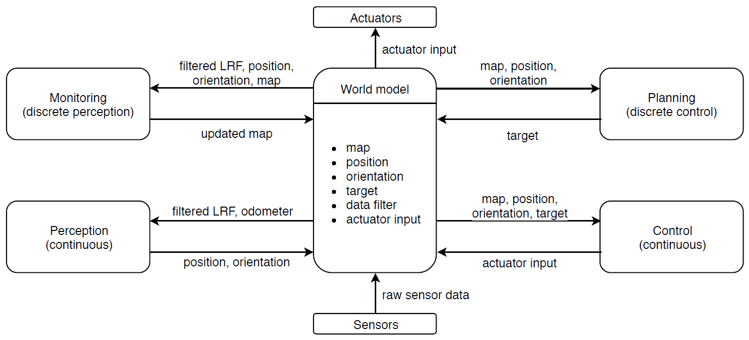
The interfaces for the initial design and the information exchanged between each interface are depicted in Figure 1.
Mapping
Feature Detection
Split and Merge
1. preprocess data(input: laser,odom)
- remove overlaping points
- push_back() them into vector, both laser and odom
- convert to xy coordinates and push_back() into vector
2. merge scan (optional)
- connect fron scan with back scan
3. find section(input: processed_laser)
- if each two points' distance larger than threshold; [math]\displaystyle{ r_{1}^2+r_{2}^2-2r_{1}r_{2}cos(\delta_{angle}) }[/math]
- true, write down the first point's index A, and next point's index B, store index in a vector
- the first initial point Z in first section, is where laser scan begin, its end point is A from above
- next section's initial point is point B from findgap(), its end point is maybe point C
- check the point number in each section, e.g. A-Z, or C-B, if the number (section length) less than threshold
- true, declare they are outlier, remove both initial and end point from index vector
- output: each section's initial point, end point's index (of whole data after merge()). may define a struct with two vectors, section.init, section.end
4. feature dectection (find corner and wall)
- may need to convert to xy coordinate
- in each section, fit the line crossing intial point and end point; [math]\displaystyle{ ax+by+c=0 }[/math], [math]\displaystyle{ a=(y_{1}-y_{2})/(x_{1}-x_{2}) }[/math], [math]\displaystyle{ b=-1 }[/math],[math]\displaystyle{ c=(x_{1}y_{2}-x_{2}y_{1})/(x_{1}-x_{2}) }[/math]
- calculate the distance from line to each point within this section; [math]\displaystyle{ abs(ax_{0}+by_{0}+c)/sqrt(a^2+b^2) }[/math]
- find max distance, if smaller than wall threshold
- true, declare it's a wall between two points, goto next step;
- fales, declare it's corner, replace initial point with the found corner, go back to step 1 in this function, write down the max distance point's index.
- connect two points that declared as wall
- connect each corner points with increasing index within current section
- connect current section's initial point with min index corner point, and max index corner point with end point
- output: a 2D vector, every row is x or y coordinates of every corner points within that section
5. merge map (update world model)
- define a 2D vector, initial is empty
- push_back() every row from step 4
- each section finally has two rows, one is x coordinate of all the corner points within that section, and another is y coordinates
Test Result
Static
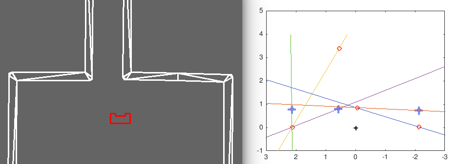
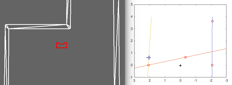
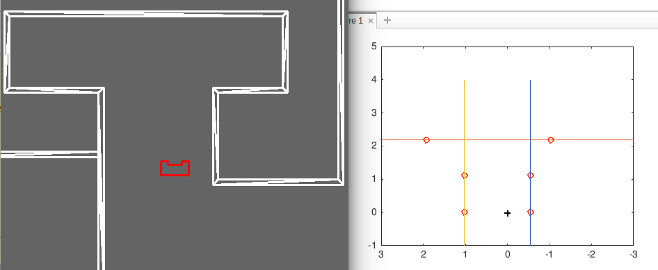
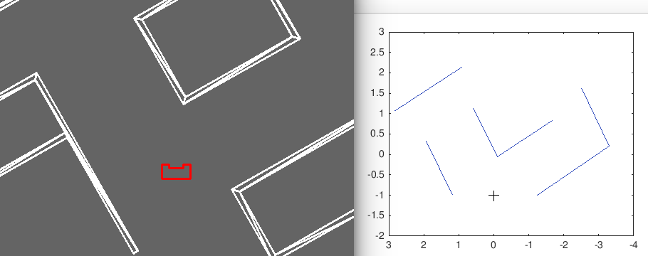
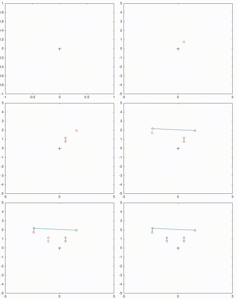
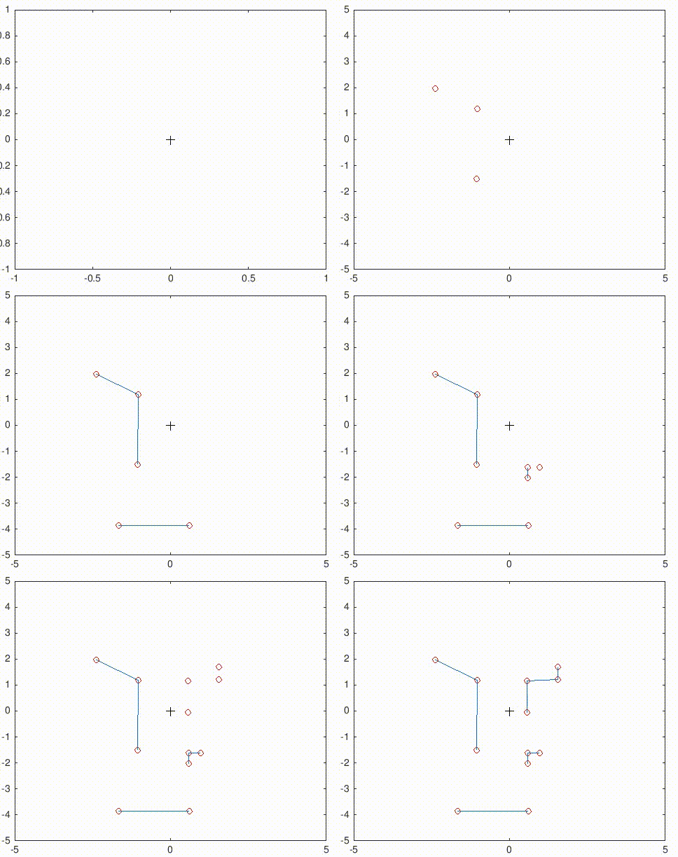
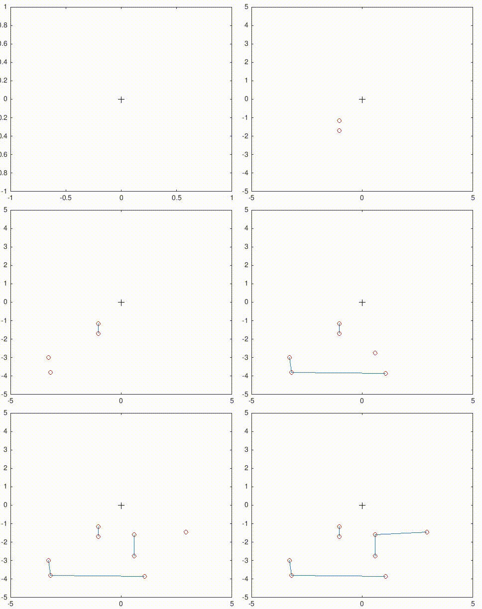
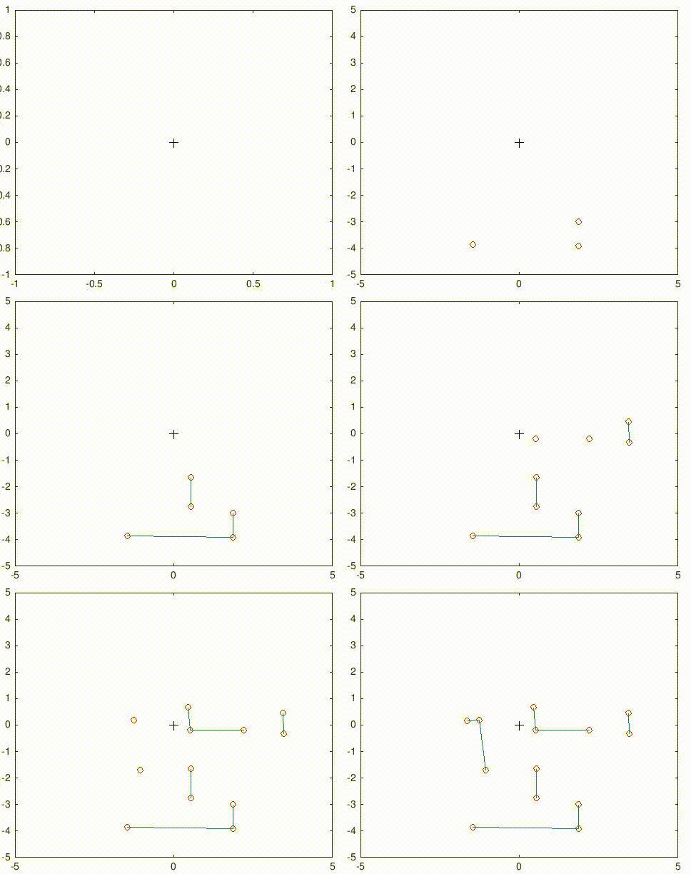
These are some results of Split & Merge that implemented in simulation.
Dynamic
The simulator gif is too large to play fluently. Link is here: http://cstwiki.wtb.tue.nl/images/Split-Merge-Simulator.gif
Bottleneck
1. Wrong corner point
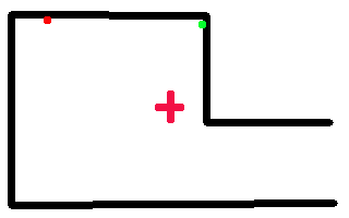
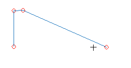
From simulation with different room setting, it's found that Split-Merge works fine when pico is not facing straight to a wall. In other words, if pico's x direction is perpendicular to the wall, it's easy to find the wrong corner.
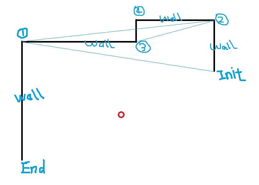
This is caused by the method to calculate distance of points within a certain section to the initial-end line, which is explained in step 4 above. When the wall is (nearly) parallel to the pico's y axis, there might be several points with similar max distance, and one of these points could happen to be the wrong corner, which is indicated by the red point below.
Solution
- Always calculate the distance of all the points from original initial to end to the line, not only calculate the updated initial point, i.e. the found corner point. This should fix the problem, but the corner index may not be monotonic.
- When a corner is found, check its neighbor points. If they could from a right angle, then it's concluded this is exactly the corner point.
- When detect a wall parallel to pico's y direction, rotate a little angle and scan once more.
2. Missing feature (corner) point
This happens when first detect a corner that has a large index that far away from init point. Then the init point is updated with the found corner, and the possbible corner with a small index that close to init point is missing.
Solution:
Rather than only connect the found corner with end point, also connect its with init point (or previous corner point, to be specific).
3. Evaluation of detected-feature quality
How to determine if a detection is good enough or just dropout?
4. Overlapping feature
The robot scans several times during competition, and some sections or features are overlapped. How to update previous feature, or how to connect them to a larger one.
Update Mapping
strategy
Robot may scan several times during the challenge and in order to deal with the information from LFR, we have to maintain a map.
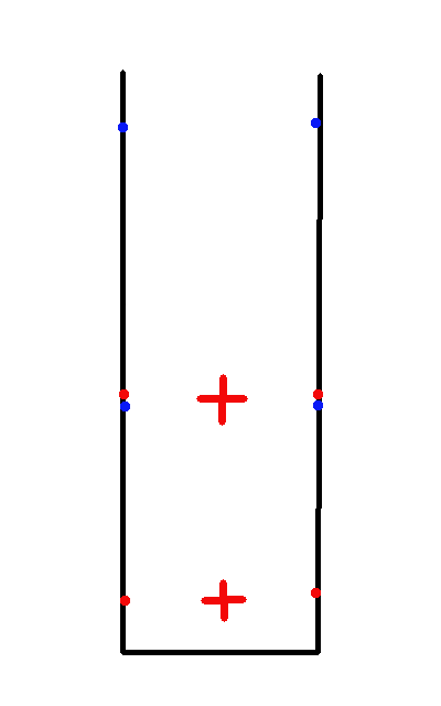
At first, we assume that robot always go to the middle point of an open space and do the scanning. The initial and end points of new scanning are always quite close to the "open" points from previous scan, or un-updated map, which is shown in the left figure below. The red points are found at first scanning, and the blue ones are found at next scanning. The distance of each blue points to the previous map (in this case, the red points) are calculated and the closest points are removed and their sections are merged.
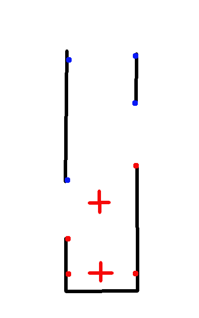
However, this is not always the case, in that we cannot either guarantee, or want that robot will always go to the middle point and scan. The right figure below illustrates this case.
Occupancy Mapping
Use a 2D array to store the map. Bresenham's line algorithm is helpful when assign value to the free cells and the cells with obstacle could be determined by LRF data and coordinates conversion.
State Machines
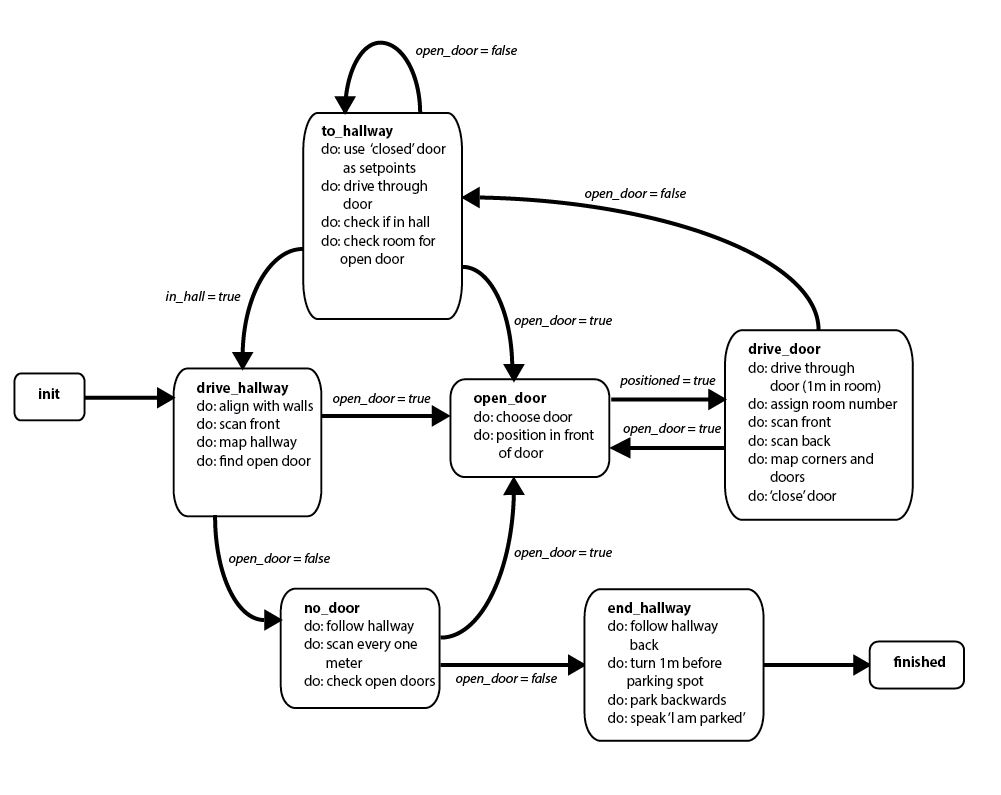
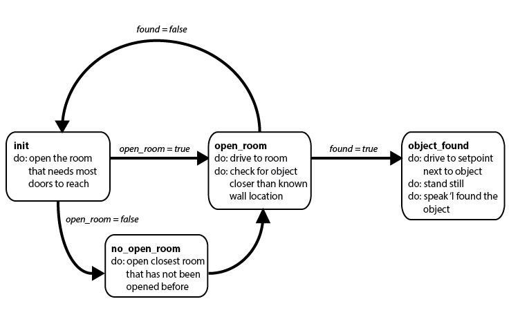
For the hospital challenge, discrete (state) control will be required. Therefore, these following two state machines have been designed for the two parts of the challenge: mapping the hospital and finding the object.
Notes
Rosbag
- Check bag info: rosbag info example.bag
- Split rosbag: while playing large rosbag file, open a new terminal, rosbag record (topic) -a --split --duration=8
- Extract rosbag data:
- In linux, rostopic echo -b example.bag -p /exampletopic > data.txt, or data.csv;
- In matlab, bag = rosbag(filename), bagInfo = rosbag('info',filename), rosbag info filename
