AutoRef Honors2019 timeline: Difference between revisions
| (2 intermediate revisions by the same user not shown) | |||
| Line 50: | Line 50: | ||
[[File:Honors_final.PNG| | <center>[[File:Honors_final.PNG|center|780px]]</center> | ||
Latest revision as of 22:42, 24 May 2020
AutoRef Honors 2019 - Timeline
Q1
The project began with a brief research period of 2-3 weeks in which the team made a short list of possible drones which could be used for the project and evaluated the strengths and weaknesses of each model. The final decision was to purchase a Crazyflie 2.1 with several accessories; including a Flowdeck unit, a USB radio signal receiver, replacement batteries and spare parts in case the drone broke during testing. The Flowdeck is a small unit which is attached to the bottom of the drone. This unit allows the drone to hover at a certain height using a LIDAR and control lateral movement using optical flow and a camera.
As soon as the drone was delivered to the university the basic functions of the drone were tested. The drone did not require many installations on the PC and the addition of the Flowdeck was plug and play. With the Flowdeck connected to the bottom of the drone it was able to hover relatively steady at a fixed height with some minor lateral drift at the click of a button.
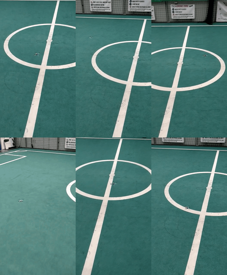
With the drone fully set up the next step was to decide how to program the drone in order to operate as a referee during a robot football game. It was decided to use a relative positioning system for the drone instead of an absolute one in order to make the system scalable to any size field. The goal was to make the drone detect the ball and maintain it within its field of view, since most of the interactions between robots during a game are likely to occur in the vicinity of the ball.
Once the goals for the project were set a presentation was given to Dr. van de Molengraft in which the team outlined the decisions made, the project goals, assumptions and future steps to take throughout the remainder of the year. Some of the feedback received included the need to be more specific with language and explanations and to fully work out the reasoning behind decisions taken by the team. As a result of this presentation and the feedback received we narrowed down the goals and made them more detailed in order to give the team a better sense of direction for the project.
Q2
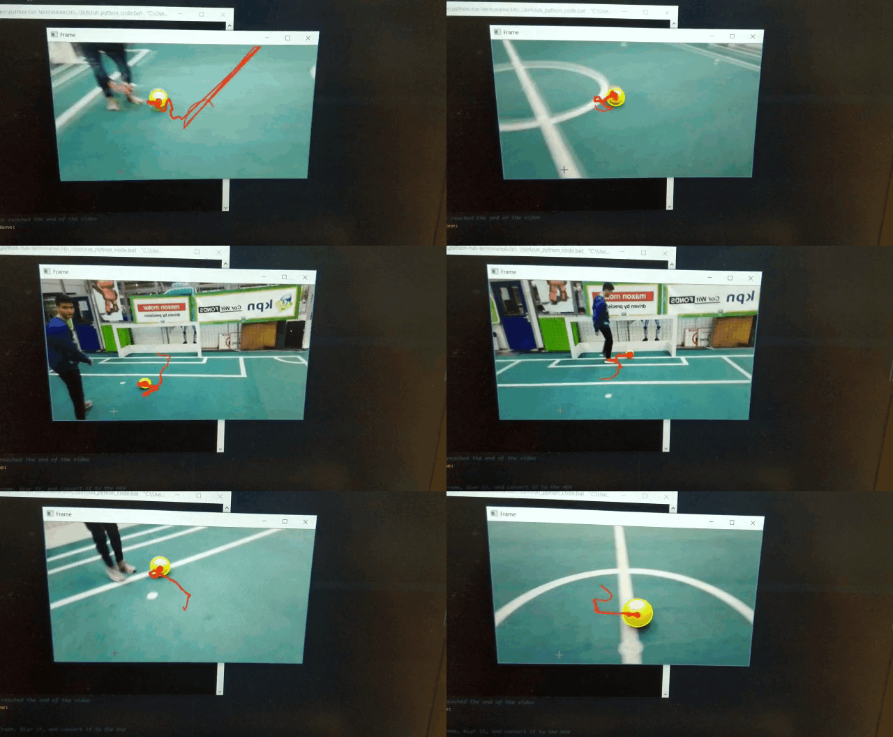
The team was split into 2 main subgroups to increase efficiency. One group focused on developing a motion command script with which the drone could be controlled remotely by passing arguments through preset functions in python continuously while the drone was flying. The other group focused on developing a python script that could detect the ball based on color using the OpenCV cv2 library. While the code developed by the team was functional, a code was found online which gave the option to alter more parameters (Rosebrock, A, 2015). The previous code was abandoned and the team focused on implementing a mask around the previous position of the ball in order to reduce false-positive detections. The final code was tested by capturing images with a digital smartphone camera and sending them to the PC running the code through Wi-Fi. The ball was always detected correctly as long as the images were clear.
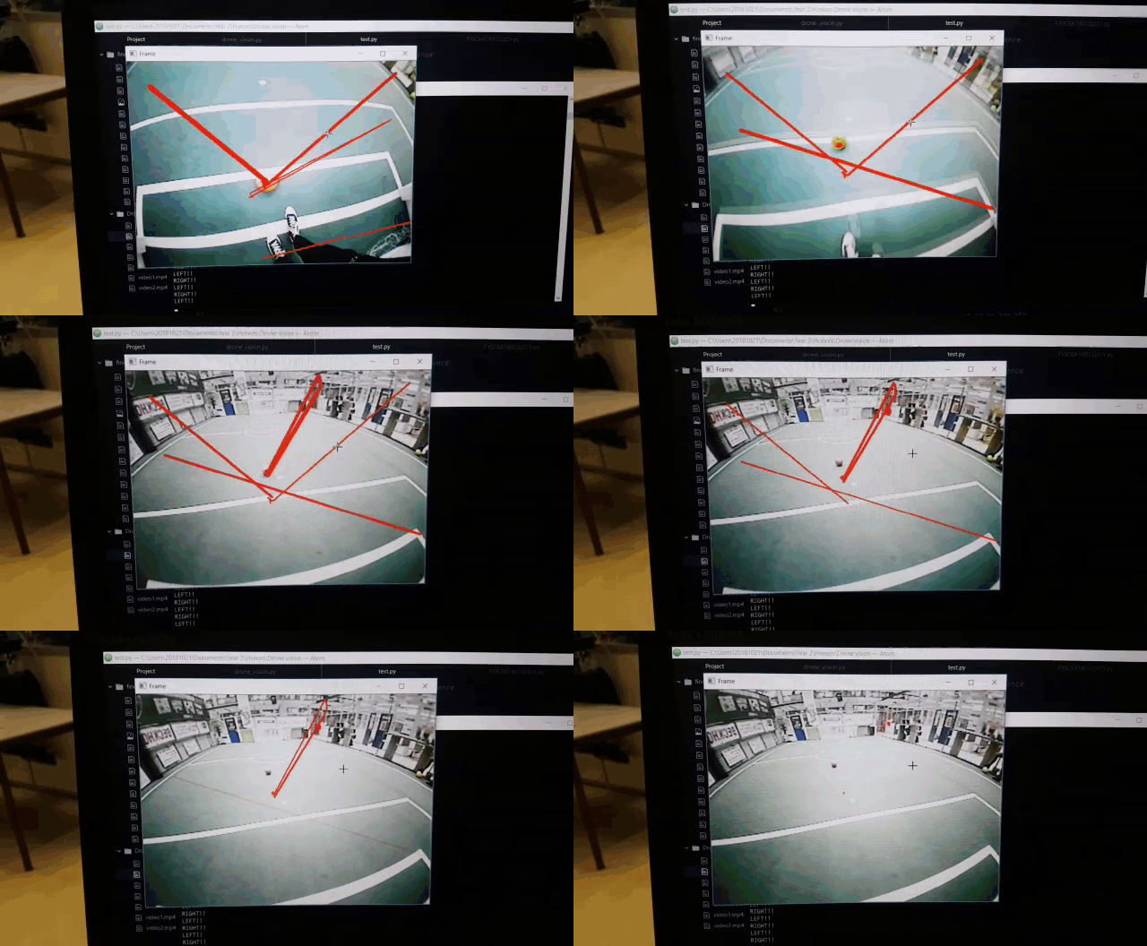
The team decided to try capturing images with an analog FPV (First Person View) camera, as these are commonly used by drone owners to control their drones at a distance due to their low latencies, which is a characteristic that seemed desirable to make the drone referee react faster to ball movements. Additionally, the drone referee could be operated in areas with no Wi-Fi connection available. Two different analog cameras were tested yielding the same result: The latency was indeed very low. However, due to the radio transmission noise the image colors were very unstable and the flicker made the color-based ball detection too unreliable to make the use of analog cameras viable.
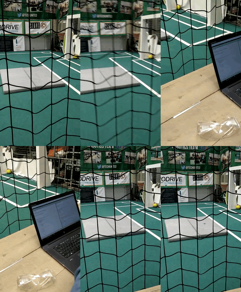
With the help of the 'motioncommander' class written by Bitcraze, scripts were written that would let the drone follow predefined paths on its own. When the vision part would be done, (velocity) commands would be sent to the control part of the drone to make it move. To make this connection possible, the team designed a python script that would take care of the communication between the vision and motion control parts. This script was tested by having as input the keyboard of a laptop. Using it, velocity setpoints could be sent to the drone in real-time controlling its flight while the drone would keep itself stable at any time.
Q3
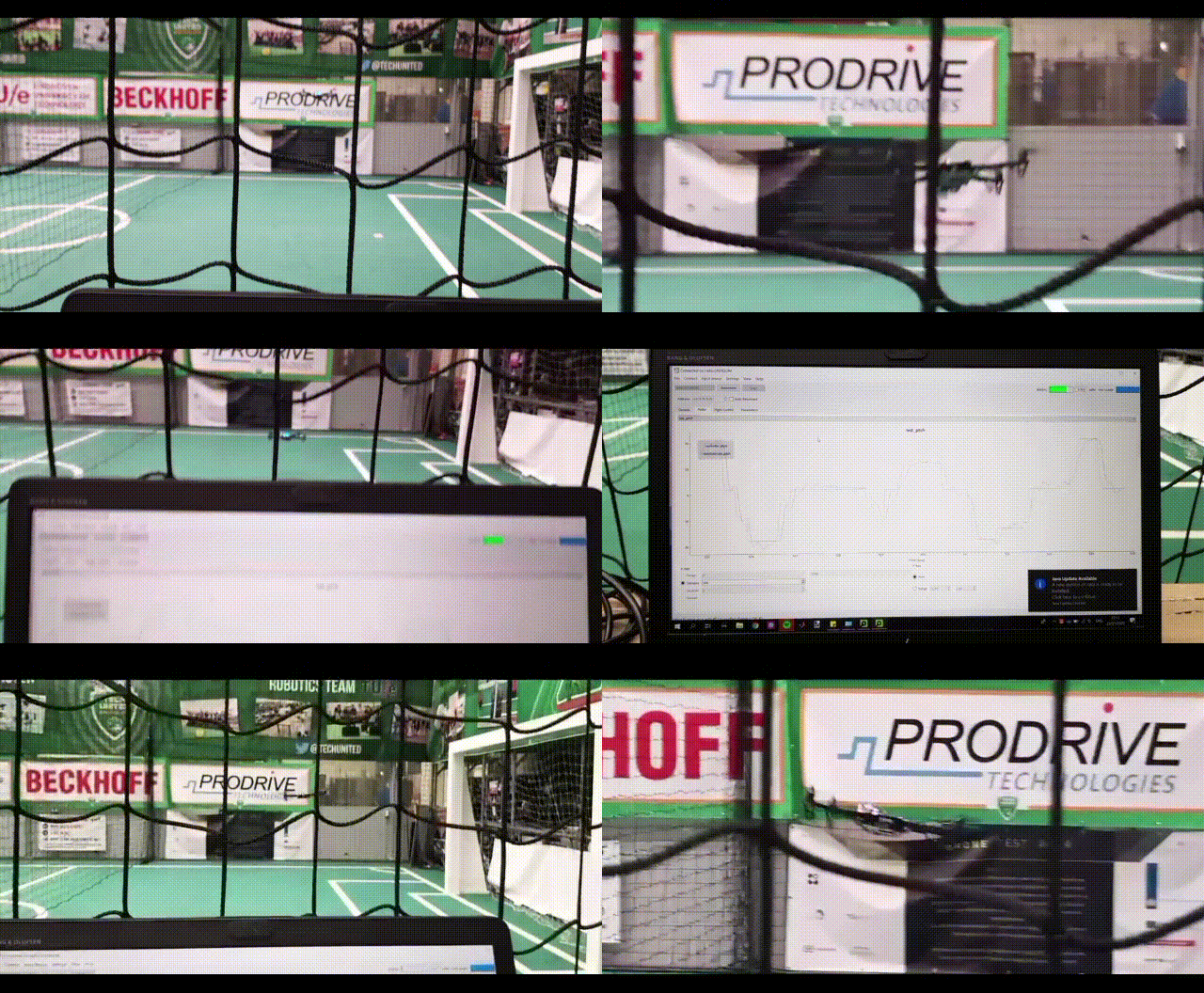
The final decision was to use a Raspberry Pi 3B+ with a 8MP digital camera module. The Raspberry would take care of the image capture and processing in its entirety and would send the coordinates of the center of the ball and its radius to the PC. The ball detection code was adapted to package the 3 variables [x, y, radius] in an array for each frame and send them to the PC using UDP (User Datagram Protocol). The motion command script was adapted to unpack the array and instruct the drone to perform an action dependent on the data received, creating a closed loop control system.
In order to support the weight of a Raspberry Pi a larger, more powerful drone was required since the Crazyflie 2.1 could only carry an additional load of 15 g. The Crazyflie brain was attached to a larger frame with more powerful motors. Some modifications were done to the wiring of the ESCs (Electronic Speed Controllers) and the controllers were PID-tuned by fixing the drone to a freely-rotating pole and tuning the controller for one axis of rotation at a time. The stability of the new drone was then tested. The Flowdeck was not yet attached to the new frame, which made the hover of the drone a lot more unstable and the lateral and vertical drift was a lot more noticeable than with the smaller frame.
Q4
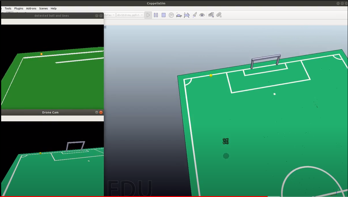
Due to the pandemic the team had no choice but to transfer as much of the progress made to a simulation environment. The simulator of choice was CoppeliaSim (previously known as V-REP). A model of a quadrotor was added to the simulation and its physical properties were altered to resemble the behavior of a real drone. Besides switching to a simulation environment, the team also adopted the framework of ROS (the Robotic Operating System). ROS will take care of the communication between the different parts of the software i.e. control and vision. An additional function of detecting lines within the playing field was added to the vision code, which already had the ball detection implemented. Finally, the position of the ball during the first 3 minutes of a real robot football match (Final game of Robocup 2019 Sydney) was used to create a path for a model of a ball. The result was a simulation in which the ball moves as it would during a real game and the drone effectively moves while keeping the ball in the center of its field of view. The drone also detected lines in its field of view, but the enforcement of the out-of-bounds rule or goal detection was not implemented due to the complicated circumstances and time constraints.
