System Architecture MSD16: Difference between revisions
| (44 intermediate revisions by one other user not shown) | |||
| Line 8: | Line 8: | ||
This paradigm defines Tasks (blue block) using the objectives set with respect to the context of the project, i.e. what needs to be done. The Skills (yellow block) then define the implementation, i.e. how to these tasks will be completed. The hardware (grey block) or the robots, i.e. the ones who will complete the tasks by implementing the skills are the agents available at the system-architects’ disposal and the choice made to pick certain agents over the other is influenced by system requirements. The system requirements are influenced by a number of factors especially the objectives and the context of the project. Coming back to the agents, they gather information from the environment and this information is first processed (filtered, fused etc.) and then stored in the world model (green block) which allows it to be accessed afterwards. Finally the visualization or the user interface (orange block) is a tool to observe how the system sees the environment. <br> | This paradigm defines Tasks (blue block) using the objectives set with respect to the context of the project, i.e. what needs to be done. The Skills (yellow block) then define the implementation, i.e. how to these tasks will be completed. The hardware (grey block) or the robots, i.e. the ones who will complete the tasks by implementing the skills are the agents available at the system-architects’ disposal and the choice made to pick certain agents over the other is influenced by system requirements. The system requirements are influenced by a number of factors especially the objectives and the context of the project. Coming back to the agents, they gather information from the environment and this information is first processed (filtered, fused etc.) and then stored in the world model (green block) which allows it to be accessed afterwards. Finally the visualization or the user interface (orange block) is a tool to observe how the system sees the environment. <br> | ||
In the task block, a sub-block is the Task Monitor (highlighted in red within the Task context block). This block was interpreted as a supervisor and a coordinator. It keeps an eye on the tasks and skills. It is possible to have some tasks which are a completed by a series of skills. In such a case it becomes important to schedule skills as these could either have to be executed sequentially or parallelly. It might become important for the system to track which skills have been completed and which need to be executed next. Task control feedback/ feedforward was not taken into consideration in much detail in the system architecture that was developed for this project. <br> | In the task block, a sub-block is the Task Monitor (highlighted in red within the Task context block). This block was interpreted as a supervisor and a coordinator. It keeps an eye on the tasks and skills. It is possible to have some tasks which are a completed by a series of skills. In such a case it becomes important to schedule skills as these could either have to be executed sequentially or parallelly. It might become important for the system to track which skills have been completed and which need to be executed next. Task control feedback/ feedforward was not taken into consideration in much detail in the system architecture that was developed for this project. <br> | ||
<center>[[File:architecture_1.png|thumb|center|600px|Architecture]]</center> | |||
= Layered Approach = | = Layered Approach = | ||
The system architecture derived from the concepts presented in the above-described paradigm can be seen below. Every block but the GUI context is highlighted in this architecture. The Coordinator block interacts with the Supervisor to determine which skills need to be executed and is assisted by the Skill Matcher in picking the right hardware agent best suited to execute the necessary skill. The concept behind the skill matcher is explained in a later section. <br> | The system architecture derived from the concepts presented in the above-described paradigm can be seen below. Every block but the GUI context is highlighted in this architecture. The Coordinator block interacts with the Supervisor to determine which skills need to be executed and is assisted by the Skill Matcher in picking the right hardware agent best suited to execute the necessary skill. The concept behind the skill matcher is explained in a later section. <br> | ||
While developing the architecture, a layered approach was used. Based on the objectives, and the requirements/constraints imposed by them, design choices were made. As shown in the Figure below starting from the top, with each subsequent layer the level of detail increases. <br> | While developing the architecture, a layered approach was used. Based on the objectives, and the requirements/constraints imposed by them, design choices were made. As shown in the Figure below starting from the top, with each subsequent layer the level of detail increases. <br> | ||
<center>[[File:layered_Approach.png|thumb|center|450px|The three layers in the architecture]]</center> | <center>[[File:layered_Approach.png|thumb|center|450px|The three layers in the architecture]]</center> | ||
| Line 27: | Line 28: | ||
= Implementation Layer = | = Implementation Layer = | ||
Referring back to the ''Three layers in the architecture'' diagram as the requirements were further refined, several design choices were made on the software and hardware. These choices were influenced not only by requirements but also by constraints. For example, using a drone and the TechUnited turtle were imposed on the project. These did not come into picture in the previous layers. The current layer of the architecture is the Implementation Layer as depicted in the figure.<br> | Referring back to the ''Three layers in the architecture'' diagram as the requirements were further refined, several design choices were made on the software and hardware. These choices were influenced not only by requirements but also by constraints. For example, using a drone and the TechUnited turtle were imposed on the project. These did not come into the picture in the previous layers. The current layer of the architecture is the Implementation Layer as depicted in the figure.<br> | ||
<center>[[File:Layer3.png|thumb|center|700px|Implementation layer in the architecture]]</center> | <center>[[File:Layer3.png|thumb|center|700px|Implementation layer in the architecture]]</center> | ||
At this level of the architecture one can write the software. The major decisions that were made here were regarding the software such as specific: <br> | At this level of the architecture, one can write the software. The major decisions that were made here were regarding the software such as specific: <br> | ||
1. image processing algorithms (=skills), <br> | 1. image processing algorithms (=skills), <br> | ||
2. sensor fusion algorithms (in the world model)and<br> | 2. sensor fusion algorithms (in the world model) and<br> | ||
3. communication protocols (communication between different hardware components).<br> | 3. communication protocols (communication between different hardware components).<br> | ||
This layer is also the realistic representation of the actual implementation the project team ended up with i.e. only the detection based tasks (and the corresponding skills). <br> | This layer is also the realistic representation of the actual implementation the project team ended up with i.e. only the detection based tasks (and the corresponding skills).<br> Below is the screen-shot of the Simulink implementation. What is highlighted here is the fact that the software developed in this project had a proper correspondence with the paradigm used of the system architecture. The congruity in the colors of the blocks here and the ones that have shown earlier in the description of the paradigm is evident. <br> | ||
The Supervisor, coordinator and the skill matcher were not in the final implementation. | |||
<center>[[File:Simulink_Arch.png|thumb|center|700px|Simulink implementation]]</center> | |||
The Supervisor, coordinator and the skill-matcher were not in the final implementation. Bu their conceptual inception is presented here and can be further worked on and included in future implementations. <br> | |||
==Skill-Matcher== | |||
For each defined skill, the skill-selector needs to determine which piece of hardware is able to perform this skill. Therefore the capabilities of each piece of hardware needs to be known and registered somewhere in a predefined standard format. These hardware capabilities can be compared to the hardware capability requirements (HCR; required in the skill framework) of each skill. This matching between hardware and skill can be done by the skill-selector during initialization of the system. To do this in a smart way, the description of the hardware configuration and the HCR need to be in a similar format. One possible way of doing this will be discussed below.<br> | |||
===Hardware configuration files=== | |||
On the approach level of the system architecture, it was decided to use moving robots with camera’s to perform the system tasks. Different robots might have different capabilities. This should not hinder the system from operating correctly. It should preferably even be possible to swap robots without losing system functionality. This is why the hardware is abstracted in the architecture. Each piece of hardware needs to know its own performance and share this information with the skill-selector. For the skill-selector to function properly, the performance of the hardware needs to be defined in a structured way. To do this, it is decided that every piece of hardware needs to have its own configuration file. In this file, a wide range of quantifiable performance indices are stored. Because one robot can have multiple cameras, the performance can be split into a robot-specific part and one or more camera parts. | |||
<center>[[File:HCR.png|thumb|center|500px|Hardware configuration]]</center> | |||
===Skill HCR=== | |||
Some skills might require some capability of the hardware (HCR) in order to perform as desired. To make it clear to the skill-matcher what these requirements are, each skill is prefixed with an HCR. This HCR should give bounds on the performance indicators in the configuration files. For instance; “to execute skill 1 a piece of hardware is required which can move in x and y-direction with at least 5 m/s”. The skill-matcher can, in turn, look at each configuration file in order to determine what hardware can drive in x and y-direction with at least this speed. As a simple first implementation, the HCR can be implemented as a structure. This structure will consist of a robot-capability structure and a camera capability structure:<br> | |||
'''Struct''' ''HCR_struct'' {RobotCap,CameraCap}<br> | |||
'''Struct''' ''RobotCap''{<br> | |||
DOF_matrix<br> | |||
Occupancy_bound_representation<br> | |||
Signal_device<br> | |||
Number_of_cams<br> | |||
}<br> | |||
'''Struct''' ''CameraCap''{<br> | |||
DOF_matrix<br> | |||
Resolution<br> | |||
Frame_rate<br> | |||
Detection_box_representation<br> | |||
}<br> | |||
Each entry in the HCR structure is already discussed. The DOF-matrix holds all information about the possible degrees of freedom and their bounds in one matrix. The rows of this matrix will represent the direction of the degree of freedom. The first column will say whether the robot has this DOF and the other columns will give upper and lower bounds. One example is given below:<br> | |||
<center>[[File:skillHCR.png|thumb|center|500px|Skill-HCR]]</center> | |||
This could reflect a robot which is able to move in the x- and y-direction and rotate around the ψ-angle. The movement in these directions is not limited in space, hence the infinite position bounds. The robot is able to drive with a maximum speed of 5 m/s and a maximum acceleration of 2 m/s^2 in both directions. It can rotate with a maximum speed of 8 rad/s and a maximum acceleration of 4 rad/s^2. For this example the bounds are symmetric, this need not necessarily be the case for each robot. A similar matrix can be made for every camera on the robot. <br> | |||
===Hardware matching=== | |||
Every skill that is implemented can be numbered, either predefined or during initialization of the system. Each hardware component and its cameras can be numbered as well. During initialization, the skill selector can check for every skill what the HCR are for that skill. It can then compare this to the configuration files of every hardware component. Based on this comparison, the hardware component can either perform the skill or not. A matrix can be constructed that stores which skill can be executed by which component. An example of such a matching matrix is given below:<br> | |||
<center>[[File:HWMatching.png|thumb|center|500px|HW Matching matrix]]</center> | |||
From this matrix it can be seen that there exist six skills in total and there are three agents available. Agent 1 has two camera’s which it can use to perform the entire set of skills. Agent 2 has only one camera and with this camera it can only perform skill 1 and 4. Agent 3 can perform all skills with camera 3 and can even perform some skills with multiple cameras. From this matrix it becomes clear that all skills can be performed with this set of agents. Some skills, like skill 6, can only be performed by two cameras while skill 1 is very well covered. This matrix can be used to determine if the set of agents is enough to cover all skills. It could also be used to determine which robot is most suited for which role, e.g. main referee and line referee. This matrix is constructed during initialization of the system. However, it could happen that an agent is added or subtracted from the system. Therefore, the skill selector should frequently check which agents are still in the system and, if necessary, update the matching matrix. <br> | |||
===Role restirctions=== | |||
If there are multiple agents in the system, it could be necessary to assign roles to each of them. This role assignment could be determined beforehand, for instance by specifying a preferred role in the configuration file of each agent. Another way to assign roles can be based on the matching matrix. Based on the skills each agent can perform the roles are divided. Some roles might impose restrictions on the agent. These restrictions can be interpreted in the same way as the HCR of the skill-framework. Where the HCR imposes some minima on the hardware requirements, the role restriction (RR) sets some maximal allowed values for the hardware. For example, the line referee is only allowed to move alongside one end of the field with a maximum linear velocity of 3 m/s. The DOF-matrix of the RR structure might look like:<br> | |||
<center>[[File:roleRestriction.png|thumb|center|500px|Role restriction matrix]]</center> | |||
Suppose the field is 12 meters long and 9 meters wide. The agent which is performing the role described by this RR is only able to move next to the field, with a margin of half a meter, over the entire length of the field. The maximal absolute velocity at which it is allowed to do this is 3 m/s.<br> | |||
===Role matching=== | |||
The RR also restricts the skills which an agent with a certain role is allowed to do. If it is decided which agent will fulfill a certain role, the matching matrix needs to be updated. This update can only remove entries in the matching matrix, since the restriction can never add functionality to the hardware. This process raises a problem: if the role assigning is done based on the matching matrix and the RR changes this matrix, the role assigning might change. This will probably call for an iterative approach to determine which agent is best fitted for a role in order to get a good coverage of all the skills. | |||
==Supervisor (and coordinator)== | |||
The supervisor is responsible for monitoring the system tasks and for coordinating the subsystems with respect to these tasks. This involves dynamically distributing subtasks amongst the subsystems in an efficient and effective manner. The operation of the supervisor can be divided into a default process flow and a set of alternative process flows. The latter are activated by a certain trigger occurring during the default process, and can be terminated by another trigger. <br> | |||
The top half of Figure 1 shows the default process flow of the supervisor. For each subsystem, the process flow is divided into two sections: one (the colored rectangle) representing processes taking place on the subsystem hardware, and one (the black rectangle) representing the processes taking place on a separate processing unit. These processing units can be one and the same, or actually separated, in which case the world model data needs to be synchronized between these units.<br> | |||
<center>[[File:supervisor_Flow.png|thumb|center|600px|Supervisor process flow]]</center> | |||
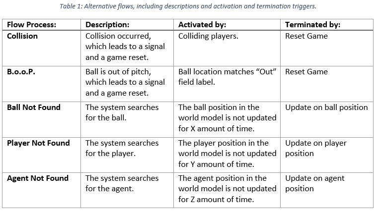
Note that the central process in this default flow is “Update World Model”, indicating that the entire default process flow revolves around maintaining an accurate World Model (WM). Information, or lack of it, in this WM can then trigger an alternative process flow. The lower half of Figure 1 shows these alternative flows, five in total. Table 1 lists the names, descriptions and activating and terminating triggers for each alternative flow. | |||
<center>[[File:table_Supervisor.png|thumb|center|600px|Alternative flows, including descriptions and activation and termination triggers.]]</center> | |||
===Supervisor Requirements=== | |||
NOTE :<br> '''&''' respresents ''' AND''' relationship between requirements. <br> '''||''' respresents '''OR''' relationship between requirements. | |||
====Skills==== | |||
=====Basic===== | |||
• Move drone<br> | |||
• Move turtle<br> | |||
• Take snapshot with top camera<br> | |||
• Take snapshot with Ai-Ball<br> | |||
• Take snapshot with Kinect<br> | |||
• Take snapshot with omnivision<br> | |||
• Whistle<br> | |||
=====Advanced===== | |||
• Detect lines<br> | |||
• Detect regions<br> | |||
• Search ball<br> | |||
• Locate ball<br> | |||
• Determine whether ball is in/out<br> | |||
• Search players<br> | |||
• Locate players<br> | |||
• Detect space between players<br> | |||
• Locate drone<br> | |||
• Plan paths for drone<br> | |||
• Locate turtle<br> | |||
• Plan paths for turtle<br> | |||
====Control automata==== | |||
<center>[[File:control_Automata_1.png|thumb|center|600px|]]</center> | |||
<center>[[File:control_Automata_2.png|thumb|center|600px|]]</center> | |||
====Observer automata==== | |||
<center>[[File:Observer_Automata_1.png|thumb|center|600px|]]</center> | |||
<center>[[File:Observer_Automata_2.png|thumb|center|600px|]]</center> | |||
====Drone movement requirements==== | |||
=====TAKEOFF===== | |||
'''&'''Battery percentage above 20%<br> | |||
'''&'''Drone position is known in world model<br> | |||
=====LAND===== | |||
'''||'''Battery percentage not above 20%<br> | |||
'''||'''Drone is outside field<br> | |||
=====(ENABLE REFERENCE TO) FLY TO HEIGHT OF 2 METER===== | |||
'''&'''Drone is (approximately) at 1 meter<br> | |||
=====MOVE TOWARDS CENTER OF FIELD===== | |||
'''&'''Drone is close to the outer line of the field<br> | |||
====Path planning Requirements==== | |||
=====PLAN PATH FOR DRONE===== | |||
'''&'''Drone is (approximately) at reference height | |||
====PLAN PATH FOR TURTLE==== | |||
'''&'''Turtle is at the side-line | |||
====Whistle Requirements==== | |||
'''||'''Ball (in snapshot) is located in region with label “out”<br> | |||
'''||'''Two objects (in snapshot) are touching (and visible as an blob) | |||
====Enable/Disable detectors==== | |||
=====LINE DETECTOR'''*'''===== | |||
'''&'''Lines are expected to be visible in a snapshot<br> | |||
'''*'''Enabling the algorithm for detecting lines will also enable the algorithm to label the regions separated by the detected lines.<br> | |||
=====COLLISION DETECTOR===== | |||
'''&'''Two players are expected to be visible in a snapshot<br> | |||
=====LOCATE BALL===== | |||
'''&''' Ball position is known in world model<br> | |||
=====LOCATE PLAYERS===== | |||
'''&''' All player positions are known in world model<br> | |||
Latest revision as of 12:37, 8 May 2017
Paradigm
There are many paradigms available for developing architecture for robotic systems. These paradigms are available in Chapter 8 in the Springer Handbook of Robotics. In this project the paradigm developed at KU Leuven in collaboration with TU Eindhoven and was used. This paradigm is followed at TechUnited.
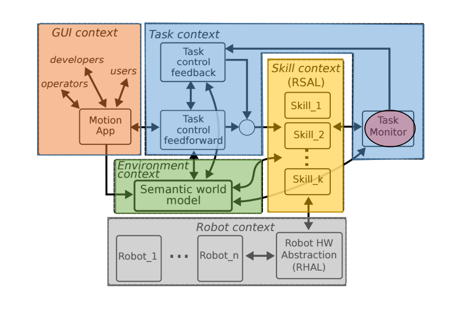
This paradigm defines Tasks (blue block) using the objectives set with respect to the context of the project, i.e. what needs to be done. The Skills (yellow block) then define the implementation, i.e. how to these tasks will be completed. The hardware (grey block) or the robots, i.e. the ones who will complete the tasks by implementing the skills are the agents available at the system-architects’ disposal and the choice made to pick certain agents over the other is influenced by system requirements. The system requirements are influenced by a number of factors especially the objectives and the context of the project. Coming back to the agents, they gather information from the environment and this information is first processed (filtered, fused etc.) and then stored in the world model (green block) which allows it to be accessed afterwards. Finally the visualization or the user interface (orange block) is a tool to observe how the system sees the environment.
In the task block, a sub-block is the Task Monitor (highlighted in red within the Task context block). This block was interpreted as a supervisor and a coordinator. It keeps an eye on the tasks and skills. It is possible to have some tasks which are a completed by a series of skills. In such a case it becomes important to schedule skills as these could either have to be executed sequentially or parallelly. It might become important for the system to track which skills have been completed and which need to be executed next. Task control feedback/ feedforward was not taken into consideration in much detail in the system architecture that was developed for this project.
Layered Approach
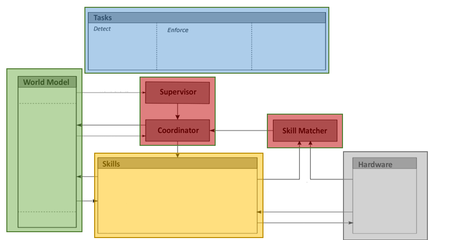
The system architecture derived from the concepts presented in the above-described paradigm can be seen below. Every block but the GUI context is highlighted in this architecture. The Coordinator block interacts with the Supervisor to determine which skills need to be executed and is assisted by the Skill Matcher in picking the right hardware agent best suited to execute the necessary skill. The concept behind the skill matcher is explained in a later section.
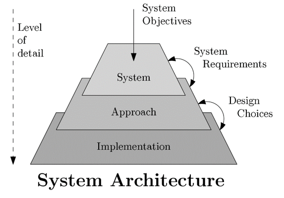
While developing the architecture, a layered approach was used. Based on the objectives, and the requirements/constraints imposed by them, design choices were made. As shown in the Figure below starting from the top, with each subsequent layer the level of detail increases.
System Layer
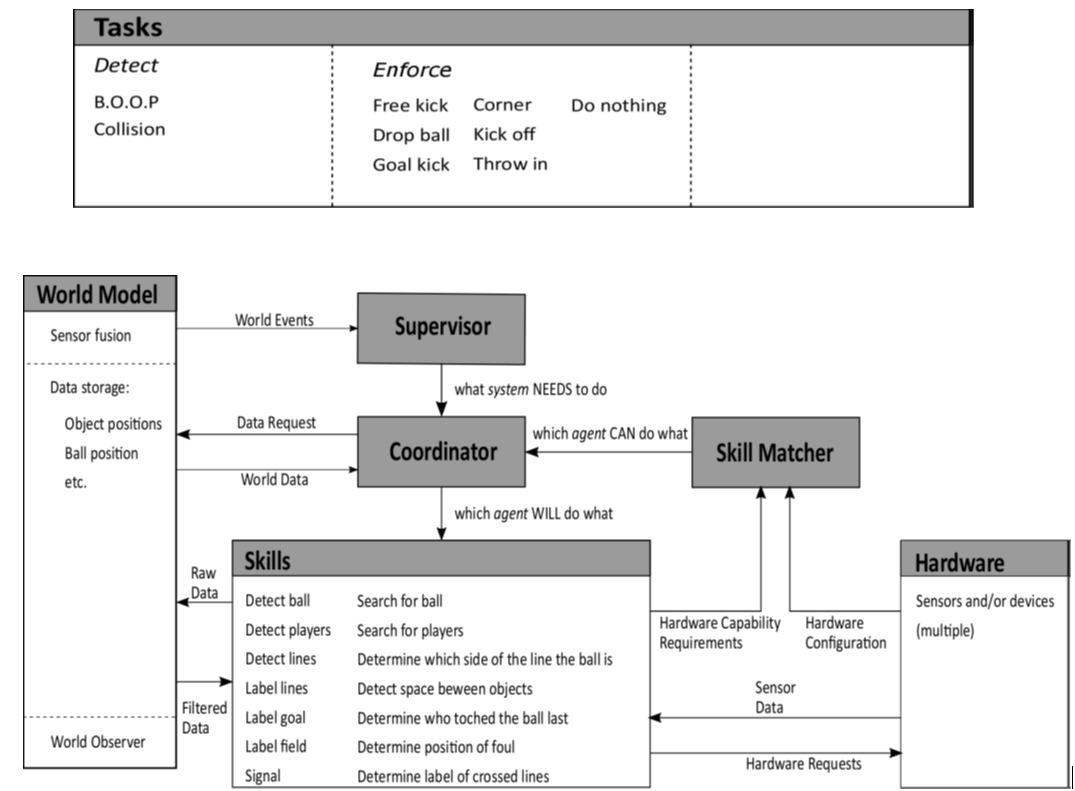
Detecting predefined events and enforcing the corresponding rules were the two main system objectives that could be taken into account for this architecture. Two events, namely
1. ball going out of pitch (B.O.O.P) and
2. collision between players
were considered to be in scope of this project. For detection and enforcement of these rules the Tasks and Skills blocks were filled as shown in the figure below.
Approach Layer
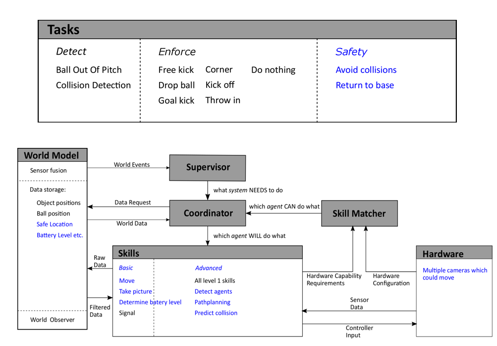
Further, by taking into account some of the system requirements one can bring more tasks and skills into the scope. For example, if one of the requirement is ‘consistency’, it can be defined as, ‘the autonomous referee system should be able to capture the gameplay dynamically’. This requirement might be further refined and result in the decision, ‘the hardware must have multiple cameras in the field which allow effective capture the active gameplay ’. Further, this decision could be polished into having ‘multiple movable cameras in the field which allow effective capture the active gameplay ’. The current layer in the architecture represents an evolution towards implementation. This is reflected in the narrowing down of the elements in the Hardware Block from Sensors and/or devices to multiple cameras which could move. Though this statement is still vague, it is more refined than its predecessor.
Implementation Layer
Referring back to the Three layers in the architecture diagram as the requirements were further refined, several design choices were made on the software and hardware. These choices were influenced not only by requirements but also by constraints. For example, using a drone and the TechUnited turtle were imposed on the project. These did not come into the picture in the previous layers. The current layer of the architecture is the Implementation Layer as depicted in the figure.
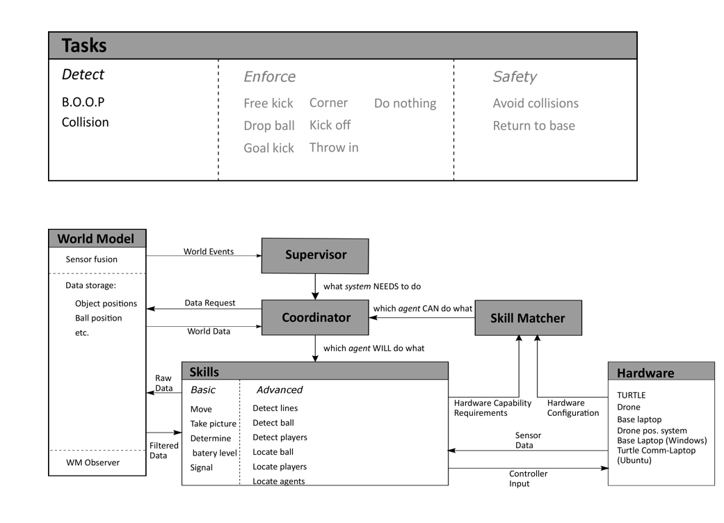
At this level of the architecture, one can write the software. The major decisions that were made here were regarding the software such as specific:
1. image processing algorithms (=skills),
2. sensor fusion algorithms (in the world model) and
3. communication protocols (communication between different hardware components).
This layer is also the realistic representation of the actual implementation the project team ended up with i.e. only the detection based tasks (and the corresponding skills).
Below is the screen-shot of the Simulink implementation. What is highlighted here is the fact that the software developed in this project had a proper correspondence with the paradigm used of the system architecture. The congruity in the colors of the blocks here and the ones that have shown earlier in the description of the paradigm is evident.
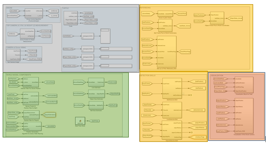
The Supervisor, coordinator and the skill-matcher were not in the final implementation. Bu their conceptual inception is presented here and can be further worked on and included in future implementations.
Skill-Matcher
For each defined skill, the skill-selector needs to determine which piece of hardware is able to perform this skill. Therefore the capabilities of each piece of hardware needs to be known and registered somewhere in a predefined standard format. These hardware capabilities can be compared to the hardware capability requirements (HCR; required in the skill framework) of each skill. This matching between hardware and skill can be done by the skill-selector during initialization of the system. To do this in a smart way, the description of the hardware configuration and the HCR need to be in a similar format. One possible way of doing this will be discussed below.
Hardware configuration files
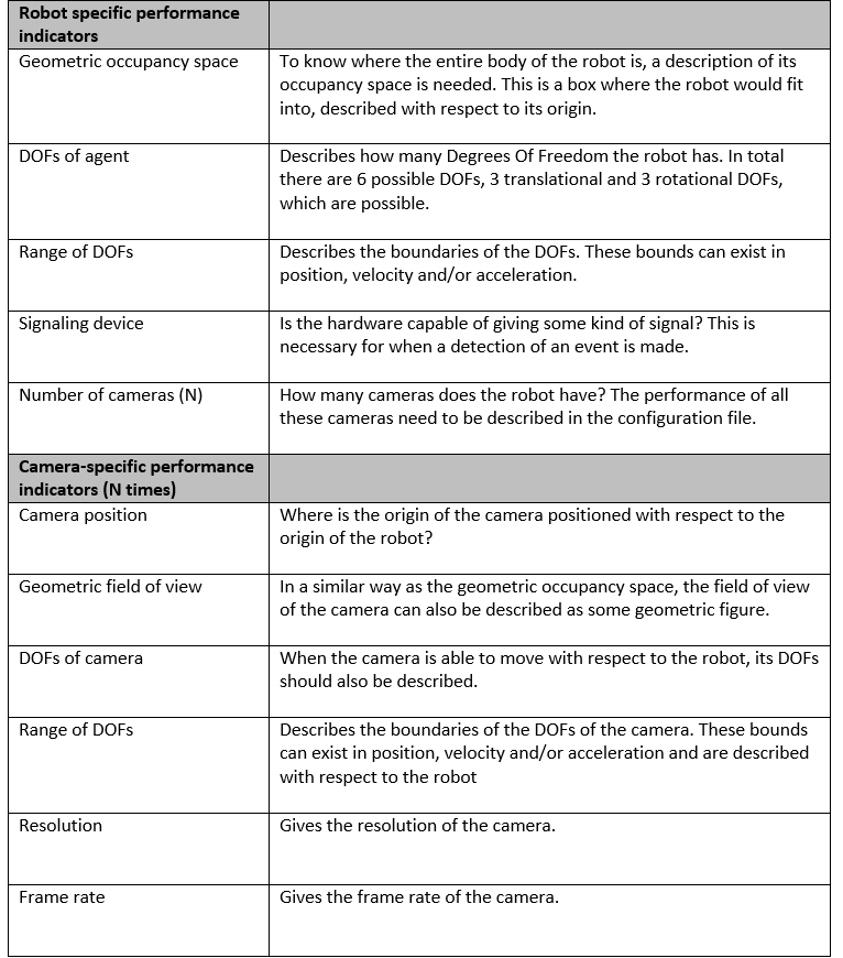
On the approach level of the system architecture, it was decided to use moving robots with camera’s to perform the system tasks. Different robots might have different capabilities. This should not hinder the system from operating correctly. It should preferably even be possible to swap robots without losing system functionality. This is why the hardware is abstracted in the architecture. Each piece of hardware needs to know its own performance and share this information with the skill-selector. For the skill-selector to function properly, the performance of the hardware needs to be defined in a structured way. To do this, it is decided that every piece of hardware needs to have its own configuration file. In this file, a wide range of quantifiable performance indices are stored. Because one robot can have multiple cameras, the performance can be split into a robot-specific part and one or more camera parts.
Skill HCR
Some skills might require some capability of the hardware (HCR) in order to perform as desired. To make it clear to the skill-matcher what these requirements are, each skill is prefixed with an HCR. This HCR should give bounds on the performance indicators in the configuration files. For instance; “to execute skill 1 a piece of hardware is required which can move in x and y-direction with at least 5 m/s”. The skill-matcher can, in turn, look at each configuration file in order to determine what hardware can drive in x and y-direction with at least this speed. As a simple first implementation, the HCR can be implemented as a structure. This structure will consist of a robot-capability structure and a camera capability structure:
Struct HCR_struct {RobotCap,CameraCap}
Struct RobotCap{
DOF_matrix
Occupancy_bound_representation
Signal_device
Number_of_cams
}
Struct CameraCap{
DOF_matrix
Resolution
Frame_rate
Detection_box_representation
}
Each entry in the HCR structure is already discussed. The DOF-matrix holds all information about the possible degrees of freedom and their bounds in one matrix. The rows of this matrix will represent the direction of the degree of freedom. The first column will say whether the robot has this DOF and the other columns will give upper and lower bounds. One example is given below:

This could reflect a robot which is able to move in the x- and y-direction and rotate around the ψ-angle. The movement in these directions is not limited in space, hence the infinite position bounds. The robot is able to drive with a maximum speed of 5 m/s and a maximum acceleration of 2 m/s^2 in both directions. It can rotate with a maximum speed of 8 rad/s and a maximum acceleration of 4 rad/s^2. For this example the bounds are symmetric, this need not necessarily be the case for each robot. A similar matrix can be made for every camera on the robot.
Hardware matching
Every skill that is implemented can be numbered, either predefined or during initialization of the system. Each hardware component and its cameras can be numbered as well. During initialization, the skill selector can check for every skill what the HCR are for that skill. It can then compare this to the configuration files of every hardware component. Based on this comparison, the hardware component can either perform the skill or not. A matrix can be constructed that stores which skill can be executed by which component. An example of such a matching matrix is given below:

From this matrix it can be seen that there exist six skills in total and there are three agents available. Agent 1 has two camera’s which it can use to perform the entire set of skills. Agent 2 has only one camera and with this camera it can only perform skill 1 and 4. Agent 3 can perform all skills with camera 3 and can even perform some skills with multiple cameras. From this matrix it becomes clear that all skills can be performed with this set of agents. Some skills, like skill 6, can only be performed by two cameras while skill 1 is very well covered. This matrix can be used to determine if the set of agents is enough to cover all skills. It could also be used to determine which robot is most suited for which role, e.g. main referee and line referee. This matrix is constructed during initialization of the system. However, it could happen that an agent is added or subtracted from the system. Therefore, the skill selector should frequently check which agents are still in the system and, if necessary, update the matching matrix.
Role restirctions
If there are multiple agents in the system, it could be necessary to assign roles to each of them. This role assignment could be determined beforehand, for instance by specifying a preferred role in the configuration file of each agent. Another way to assign roles can be based on the matching matrix. Based on the skills each agent can perform the roles are divided. Some roles might impose restrictions on the agent. These restrictions can be interpreted in the same way as the HCR of the skill-framework. Where the HCR imposes some minima on the hardware requirements, the role restriction (RR) sets some maximal allowed values for the hardware. For example, the line referee is only allowed to move alongside one end of the field with a maximum linear velocity of 3 m/s. The DOF-matrix of the RR structure might look like:

Suppose the field is 12 meters long and 9 meters wide. The agent which is performing the role described by this RR is only able to move next to the field, with a margin of half a meter, over the entire length of the field. The maximal absolute velocity at which it is allowed to do this is 3 m/s.
Role matching
The RR also restricts the skills which an agent with a certain role is allowed to do. If it is decided which agent will fulfill a certain role, the matching matrix needs to be updated. This update can only remove entries in the matching matrix, since the restriction can never add functionality to the hardware. This process raises a problem: if the role assigning is done based on the matching matrix and the RR changes this matrix, the role assigning might change. This will probably call for an iterative approach to determine which agent is best fitted for a role in order to get a good coverage of all the skills.
Supervisor (and coordinator)
The supervisor is responsible for monitoring the system tasks and for coordinating the subsystems with respect to these tasks. This involves dynamically distributing subtasks amongst the subsystems in an efficient and effective manner. The operation of the supervisor can be divided into a default process flow and a set of alternative process flows. The latter are activated by a certain trigger occurring during the default process, and can be terminated by another trigger.
The top half of Figure 1 shows the default process flow of the supervisor. For each subsystem, the process flow is divided into two sections: one (the colored rectangle) representing processes taking place on the subsystem hardware, and one (the black rectangle) representing the processes taking place on a separate processing unit. These processing units can be one and the same, or actually separated, in which case the world model data needs to be synchronized between these units.
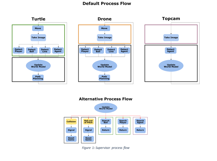
Note that the central process in this default flow is “Update World Model”, indicating that the entire default process flow revolves around maintaining an accurate World Model (WM). Information, or lack of it, in this WM can then trigger an alternative process flow. The lower half of Figure 1 shows these alternative flows, five in total. Table 1 lists the names, descriptions and activating and terminating triggers for each alternative flow.
Supervisor Requirements
NOTE :
& respresents AND relationship between requirements.
|| respresents OR relationship between requirements.
Skills
Basic
• Move drone
• Move turtle
• Take snapshot with top camera
• Take snapshot with Ai-Ball
• Take snapshot with Kinect
• Take snapshot with omnivision
• Whistle
Advanced
• Detect lines
• Detect regions
• Search ball
• Locate ball
• Determine whether ball is in/out
• Search players
• Locate players
• Detect space between players
• Locate drone
• Plan paths for drone
• Locate turtle
• Plan paths for turtle
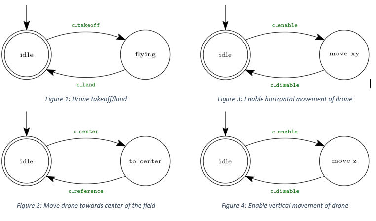
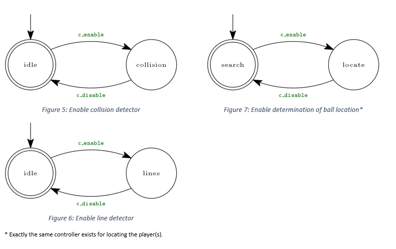
Control automata
Observer automata
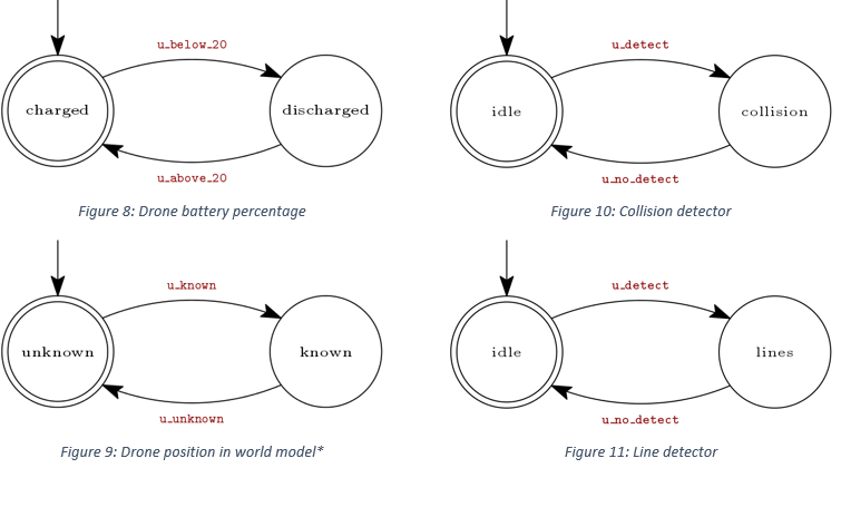
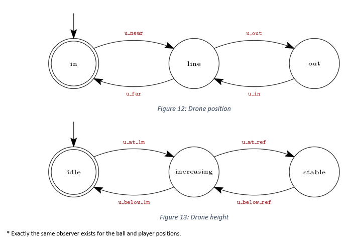
Drone movement requirements
TAKEOFF
&Battery percentage above 20%
&Drone position is known in world model
LAND
||Battery percentage not above 20%
||Drone is outside field
(ENABLE REFERENCE TO) FLY TO HEIGHT OF 2 METER
&Drone is (approximately) at 1 meter
MOVE TOWARDS CENTER OF FIELD
&Drone is close to the outer line of the field
Path planning Requirements
PLAN PATH FOR DRONE
&Drone is (approximately) at reference height
PLAN PATH FOR TURTLE
&Turtle is at the side-line
Whistle Requirements
||Ball (in snapshot) is located in region with label “out”
||Two objects (in snapshot) are touching (and visible as an blob)
Enable/Disable detectors
LINE DETECTOR*
&Lines are expected to be visible in a snapshot
*Enabling the algorithm for detecting lines will also enable the algorithm to label the regions separated by the detected lines.
COLLISION DETECTOR
&Two players are expected to be visible in a snapshot
LOCATE BALL
& Ball position is known in world model
LOCATE PLAYERS
& All player positions are known in world model