Hardware MSD16: Difference between revisions
| (20 intermediate revisions by 3 users not shown) | |||
| Line 1: | Line 1: | ||
{{:Content_MSD16_small}} | <div STYLE="float: left; width:80%"> | ||
</div><div style="width: 35%; float: right;"><center>{{:Content_MSD16_small}}</center></div> | |||
__TOC__ | |||
== Drone == | == Drone == | ||
| Line 11: | Line 12: | ||
===Experiments, Measurements, Modifications=== | ===Experiments, Measurements, Modifications=== | ||
==== Swiveled Camera ==== | ==== Swiveled Camera ==== | ||
As mentioned before, the drone has its own camera and this camera is used to catch images. | As mentioned before, the drone has its own camera and this camera is used to catch images. The camera is placed in front of the drone. However for the refereeing, it should look to the bottom side. Therefore it will be disassembled and will be connected to a swivel to tilt down 90 degrees. This will create some change in the structures. When this change is finished, it will be added here. | ||
==== Software Restrictions on Image Processing ==== | ==== Software Restrictions on Image Processing ==== | ||
Using a commercial and non-modifiable drone in this manner brings some difficulties. Since the source code of the drone is not open, it is very hard to reach some data on the drone including the images of the camera. The image processing will be achieved in MATLAB. However, taking snapshots from the drone camera directly using MATLAB is not possible with its built-in software. Therefore an indirect way is required and this causes some processing time. The best time obtained with the current capturing algorithm is 0.4 Hz using 360p standard resolution (640x360). Although the camera can capture images with higher resolution, processing will be achieved using this resolution to decrease the required processing time. | Using a commercial and non-modifiable drone in this manner brings some difficulties. Since the source code of the drone is not open, it is very hard to reach some data on the drone including the images of the camera. The image processing will be achieved in MATLAB. However, taking snapshots from the drone camera directly using MATLAB is not possible with its built-in software. Therefore an indirect way is required and this causes some processing time. The best time obtained with the current capturing algorithm is 0.4 Hz using 360p standard resolution (640x360). Although the camera can capture images with higher resolution, processing will be achieved using this resolution to decrease the required processing time. | ||
====FOV Measurement ==== | ====FOV Measurement ==== | ||
One of the most important properties of a vision system is the field of view (FOV) angle. The definition of the field of view angle can be seen | One of the most important properties of a vision system is the field of view (FOV) angle. The definition of the field of view angle can be seen in the figure. The captured images has a ratio of 16:9. Using this fact and after some measurements the achieved measurements showed that it is near to 70° view although given that the camera has 92° diagonal FOV. The achieved measurements and obtained results are summarized in Table 2 . Here corresponding distance per pixel is calculated in standard resolution (640x360). | ||
[[File:Field1.png|thumb|centre|500px]] | |||
[[File:Table2.png|thumb|centre|500px]] | |||
=== Initialization === | |||
The following properties have to be initialized to be able to use the drone. For the particular drone that is used during this project, these properties have the values indicated by <value>: | |||
* SSID <ardrone2> | |||
* Remote host <192.168.1.1> | |||
* Control | |||
** Local port <5556> | |||
* Navdata | |||
** Local port <5554> | |||
** Timeout <1 ms> | |||
** Input buffer size <500 bytes> | |||
** Byte order <litte-endian> | |||
Note that for all properties to initialize the UDP objects that are not mentioned here, MATLAB's default values are used. | |||
After initializing the UDP objects, the Navdata stream must be initiated by following the steps in the picture below. | |||
[[File:navdata_initiation.png|thumb|centre|600px|Navdata stream initiation <ref name=sdk>[http://developer.parrot.com/docs/SDK2/ "AR.Drone SDK2"]</ref>]] | |||
Finally, a reference of the horizontal plane has to be set for the drone internal control system by sending the command FTRIM. <ref name=sdk /> | |||
=== Wrapper === | |||
As seen in the initialization, the drone can be seen as a block with expects a UDP packet containing a string as input and which gives an array of 500 bytes as output. To make communicating with this block easier, a wrapper function is written that ensures that the both the input and output are doubles. To be more precise, the input is a vector of four values between -1 and 1 where the first two represent the tilt in front (x) and left (y) direction respectively. The third value is the speed in vertical (z) direction and the fourth is the angular speed (psi) around the z-axis. The output of the block is as follows: | |||
* Battery percentage [%] | |||
* Rotation around x (roll) [°] | |||
* Rotation around y (pitch) [°] | |||
* Rotation around z (yaw) [°] | |||
* Velocity in x [m/s] | |||
* Velocity in y [m/s] | |||
* Position in z (altitude) [m] | |||
== Top-Camera == | == Top-Camera == | ||
| Line 26: | Line 60: | ||
== TechUnited TURTLE == | == TechUnited TURTLE == | ||
Originally, the Turtle is constructed and programmed to be a football playing robot. The details on the mechanical design and the software developed for the robots can be found [http://www.techunited.nl/wiki/index.php?title=Hardware here] and [http://www.techunited.nl/wiki/index.php?title=Software here] respectively. | |||
For this project it was to be used as a referee. All the software that has been developed at TechUnited did not need any further expansion as some part of the extensive code could be used to fulfill the role of the referee. This is explained in the section ''Software/Communication Protocol Implementation'' of this wiki-page. | |||
== Player == | |||
[[File:omnibot.jpeg|thumb|centre|600px|Omnibot with and without protection cover]] | |||
The robots that are used as football players are shown in the picture. In the right side of the picture, the robot is shown as it was delivered at the start of the project. This robot contains a Raspberry Pi, an Arduino and three motors (including encoders/controllers) to control three omni-wheels independently. Left of this robot, a copy including a cover is shown. This cover must prevent the robots from being damaged when they are colliding. Since one of the goals of the project is to detect collisions, it must be possible to collide more than once. | |||
To control the robot, Arduino code and a Python script to run on the Raspberry Pi are provided. The python script can receive strings via UDP over Wi-Fi. Furthermore, it processes these strings and sends commands to the Arduino via USB. To control the drone with a Windows device, MATLAB functions are implemented. Moreover, an Android application is developed to be able to control the robot with a smartphone. All the code can be found on GitHub.<ref name=git>[https://github.com/guidogithub/jamesbond/ "GitHub"]</ref> | |||
==References== | |||
<references/> | |||
Latest revision as of 15:21, 28 March 2017
Drone
In the autonomous referee project, commercially available AR Parrot Drone Elite Edition 2.0 is used for the refereeing issues. The built-in properties of the drone that given in the manufacturer’s website are listed below in Table 1. Note that only the useful properties are covered, the internal properties of the drone are excluded.

The drone is designed as a consumer product and it can be controlled via a mobile phone thanks to its free software (both for Android and iOS) and send high quality HD streaming videos to the mobile phone. The drone has a front camera whose capabilities are given in Table 1. It has its own built-in computer, controller, driver electronics etc. Since it is a consumer product, its design, body and controller are very robust. Therefore, in this project, the drone own structure, control electronics and software are decided to use for positioning of the drone. Apart from that, the controlling of a drone is complicated and is also out of scope of the project.
Experiments, Measurements, Modifications
Swiveled Camera
As mentioned before, the drone has its own camera and this camera is used to catch images. The camera is placed in front of the drone. However for the refereeing, it should look to the bottom side. Therefore it will be disassembled and will be connected to a swivel to tilt down 90 degrees. This will create some change in the structures. When this change is finished, it will be added here.
Software Restrictions on Image Processing
Using a commercial and non-modifiable drone in this manner brings some difficulties. Since the source code of the drone is not open, it is very hard to reach some data on the drone including the images of the camera. The image processing will be achieved in MATLAB. However, taking snapshots from the drone camera directly using MATLAB is not possible with its built-in software. Therefore an indirect way is required and this causes some processing time. The best time obtained with the current capturing algorithm is 0.4 Hz using 360p standard resolution (640x360). Although the camera can capture images with higher resolution, processing will be achieved using this resolution to decrease the required processing time.
FOV Measurement
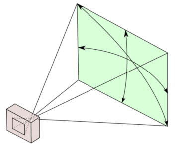
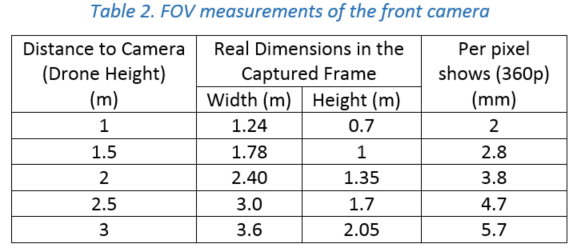
One of the most important properties of a vision system is the field of view (FOV) angle. The definition of the field of view angle can be seen in the figure. The captured images has a ratio of 16:9. Using this fact and after some measurements the achieved measurements showed that it is near to 70° view although given that the camera has 92° diagonal FOV. The achieved measurements and obtained results are summarized in Table 2 . Here corresponding distance per pixel is calculated in standard resolution (640x360).


Initialization
The following properties have to be initialized to be able to use the drone. For the particular drone that is used during this project, these properties have the values indicated by <value>:
- SSID <ardrone2>
- Remote host <192.168.1.1>
- Control
- Local port <5556>
- Navdata
- Local port <5554>
- Timeout <1 ms>
- Input buffer size <500 bytes>
- Byte order <litte-endian>
Note that for all properties to initialize the UDP objects that are not mentioned here, MATLAB's default values are used.
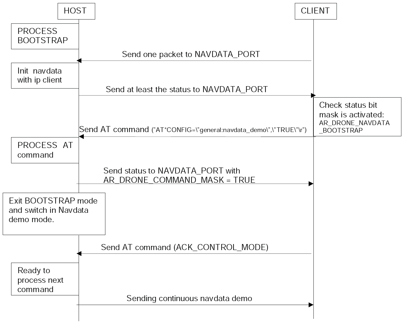
After initializing the UDP objects, the Navdata stream must be initiated by following the steps in the picture below.

Finally, a reference of the horizontal plane has to be set for the drone internal control system by sending the command FTRIM. [1]
Wrapper
As seen in the initialization, the drone can be seen as a block with expects a UDP packet containing a string as input and which gives an array of 500 bytes as output. To make communicating with this block easier, a wrapper function is written that ensures that the both the input and output are doubles. To be more precise, the input is a vector of four values between -1 and 1 where the first two represent the tilt in front (x) and left (y) direction respectively. The third value is the speed in vertical (z) direction and the fourth is the angular speed (psi) around the z-axis. The output of the block is as follows:
- Battery percentage [%]
- Rotation around x (roll) [°]
- Rotation around y (pitch) [°]
- Rotation around z (yaw) [°]
- Velocity in x [m/s]
- Velocity in y [m/s]
- Position in z (altitude) [m]
Top-Camera
The topcam is a camera that is fixed above the playing field. This camera is used to estimate the location and orientation of the drone. This estimation is used as feedback for the drone to position itself to a desired location. The topcam can stream images with a framerate of 30 Hz to the laptop, but searching the image for the drone (i.e. image processing) might be slower. This is not a problem, since the positioning of the drone itself is far from perfect and not critical as well. As long as the target of interest (ball, players) is within the field of view of the drone, it is acceptable.
Ai-Ball
TechUnited TURTLE
Originally, the Turtle is constructed and programmed to be a football playing robot. The details on the mechanical design and the software developed for the robots can be found here and here respectively.
For this project it was to be used as a referee. All the software that has been developed at TechUnited did not need any further expansion as some part of the extensive code could be used to fulfill the role of the referee. This is explained in the section Software/Communication Protocol Implementation of this wiki-page.
Player

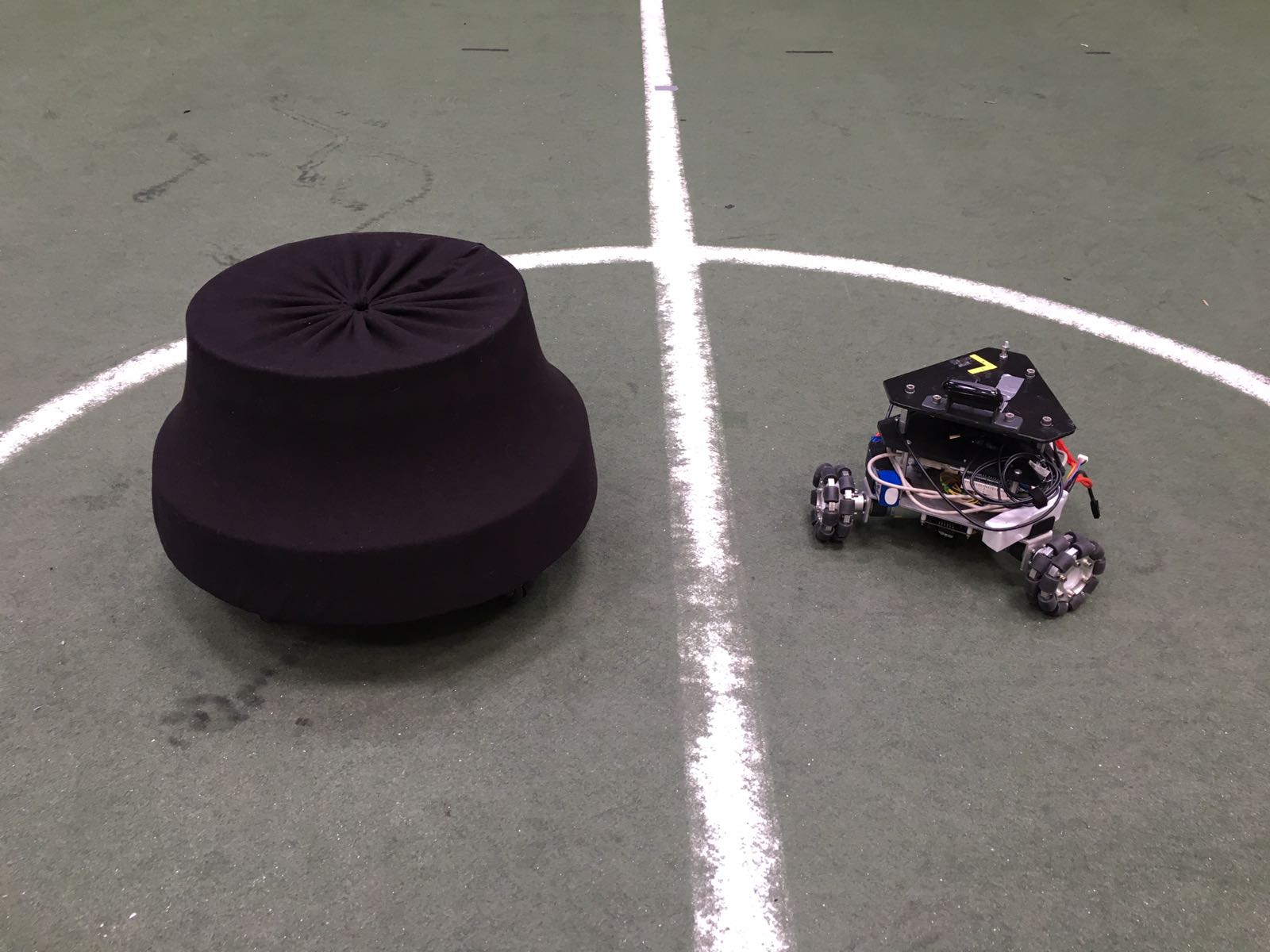
The robots that are used as football players are shown in the picture. In the right side of the picture, the robot is shown as it was delivered at the start of the project. This robot contains a Raspberry Pi, an Arduino and three motors (including encoders/controllers) to control three omni-wheels independently. Left of this robot, a copy including a cover is shown. This cover must prevent the robots from being damaged when they are colliding. Since one of the goals of the project is to detect collisions, it must be possible to collide more than once.
To control the robot, Arduino code and a Python script to run on the Raspberry Pi are provided. The python script can receive strings via UDP over Wi-Fi. Furthermore, it processes these strings and sends commands to the Arduino via USB. To control the drone with a Windows device, MATLAB functions are implemented. Moreover, an Android application is developed to be able to control the robot with a smartphone. All the code can be found on GitHub.[2]