System Architecture MSD16: Difference between revisions
| Line 26: | Line 26: | ||
<center>[[File:Layered2.png|thumb|center|750px|The approach layer of the architecture]]</center> | <center>[[File:Layered2.png|thumb|center|750px|The approach layer of the architecture]]</center> | ||
= Implementation Layer = | = Implementation Layer = | ||
Referring back to the [Pyramid Diagram] as the requirements were further refined, several design choices were made on the software and hardware. These choices were influenced not only by requirements but also by constraints. For example, using a drone and the TechUnited turtle were imposed on the project. These did not come into picture in the previous layers. The current layer of the architecture is the Implementation Layer as depicted in the figure. | |||
Revision as of 17:22, 4 May 2017
Paradigm
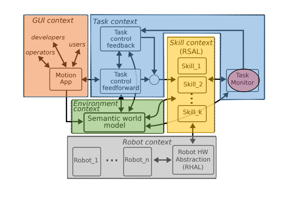
There are many paradigms available for developing architecture for robotic systems. These paradigms are available in Chapter 8 in the Springer Handbook of Robotics. In this project the paradigm developed at KU Leuven in collaboration with TU Eindhoven and was used. This paradigm is followed at TechUnited.
This paradigm defines Tasks (blue block) using the objectives set with respect to the context of the project, i.e. what needs to be done. The Skills (yellow block) then define the implementation, i.e. how to these tasks will be completed. The hardware (grey block) or the robots, i.e. the ones who will complete the tasks by implementing the skills are the agents available at the system-architects’ disposal and the choice made to pick certain agents over the other is influenced by system requirements. The system requirements are influenced by a number of factors especially the objectives and the context of the project. Coming back to the agents, they gather information from the environment and this information is first processed (filtered, fused etc.) and then stored in the world model (green block) which allows it to be accessed afterwards. Finally the visualization or the user interface (orange block) is a tool to observe how the system sees the environment.
In the task block, a sub-block is the Task Monitor (highlighted in red within the Task context block). This block was interpreted as a supervisor and a coordinator. It keeps an eye on the tasks and skills. It is possible to have some tasks which are a completed by a series of skills. In such a case it becomes important to schedule skills as these could either have to be executed sequentially or parallelly. It might become important for the system to track which skills have been completed and which need to be executed next. Task control feedback/ feedforward was not taken into consideration in much detail in the system architecture that was developed for this project.
Layered Approach
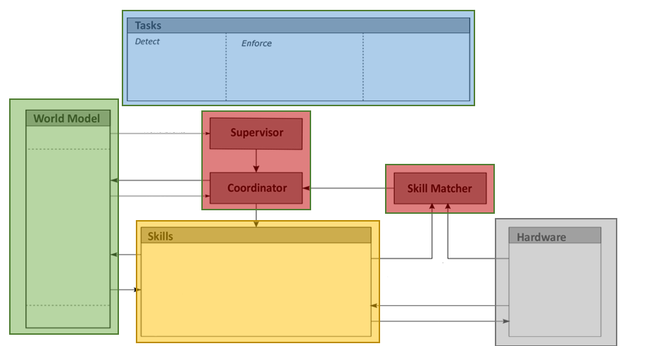
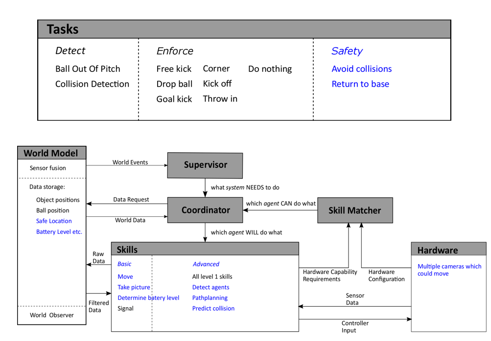
The system architecture derived from the concepts presented in the above-described paradigm can be seen below. Every block but the GUI context is highlighted in this architecture. The Coordinator block interacts with the Supervisor to determine which skills need to be executed and is assisted by the Skill Matcher in picking the right hardware agent best suited to execute the necessary skill. The concept behind the skill matcher is explained in a later section.
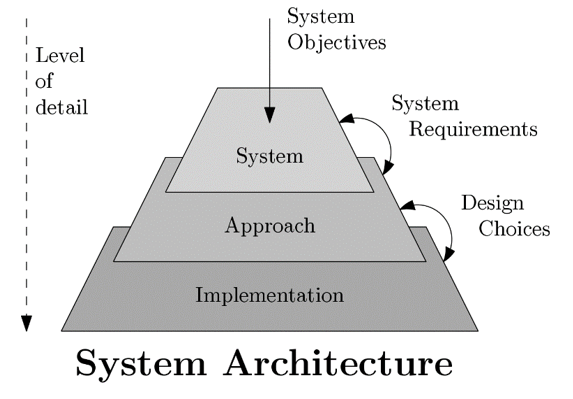
While developing the architecture, a layered approach was used. Based on the objectives, and the requirements/constraints imposed by them, design choices were made. As shown in the Figure below starting from the top, with each subsequent layer the level of detail increases.
System Layer
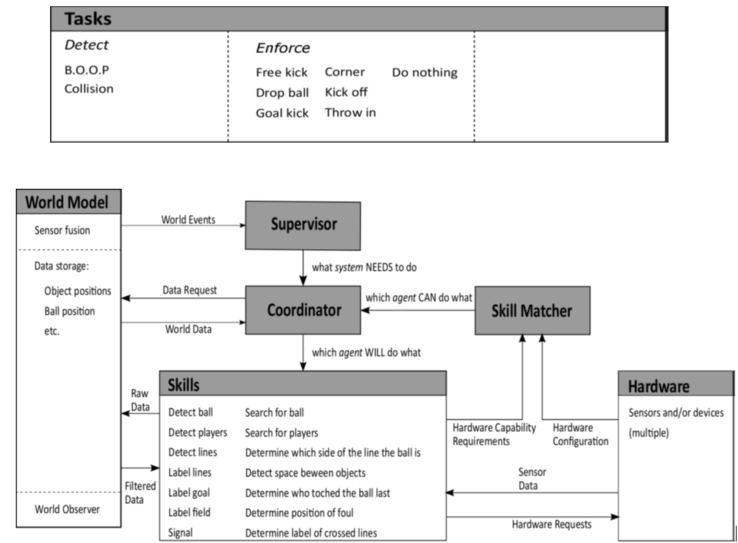
Detecting predefined events and enforcing the corresponding rules were the two main system objectives that could be taken into account for this architecture. Two events, namely
1. ball going out of pitch (B.O.O.P) and
2. collision between players
were considered to be in scope of this project. For detection and enforcement of these rules the Tasks and Skills blocks were filled as shown in the figure below.
Approach Layer
Further, by taking into account some of the system requirements () one can bring more tasks and skills into the scope. For example, if one of the requirement is ‘consistency’, it can be defined as, ‘the autonomous referee system should be able to capture the gameplay dynamically’. This requirement might be further refined and result in the decision, ‘the hardware must have multiple cameras in the field which allow effective capture the active gameplay ’. Further, this decision could be polished into having ‘multiple movable cameras in the field which allow effective capture the active gameplay ’. The current layer in the architecture represents an evolution towards implementation. This is reflected in the narrowing down of the elements in the Hardware Block from Sensors and/or devices to multiple cameras which could move. Though this statement is still vague, it is more refined than its predecessor.
Implementation Layer
Referring back to the [Pyramid Diagram] as the requirements were further refined, several design choices were made on the software and hardware. These choices were influenced not only by requirements but also by constraints. For example, using a drone and the TechUnited turtle were imposed on the project. These did not come into picture in the previous layers. The current layer of the architecture is the Implementation Layer as depicted in the figure.
