Embedded Motion Control 2015 Group 3/Scan: Difference between revisions
| (3 intermediate revisions by 2 users not shown) | |||
| Line 3: | Line 3: | ||
This page is part of the [[Embedded_Motion_Control_2015_Group_3|EMC03 CST-wiki]]. | This page is part of the [[Embedded_Motion_Control_2015_Group_3|EMC03 CST-wiki]]. | ||
In order to solve the maze, the robot needs to be able to drive autonomously. One type of data that is available is the laser range finder data. The PICO robot has a 270 degrees view, | In order to solve the maze, the robot needs to be able to drive autonomously. One type of data that is available is the laser range finder data. The PICO robot has a 270 degrees view, divided in approximately a thousand increments. | ||
=== Potential field === | === Potential field === | ||
| Line 17: | Line 17: | ||
=== Collision avoidance === | === Collision avoidance === | ||
The first level of safety is provided by the potential field algorithm. Its resultant vector will always point towards the direction with the most room and therefore it is sufficient as first layer. However, avoidance collision is one of the top priorities, since if Pico bumps into the wall, the attempt of solving the maze has failed. Another safety layer has been implemented to prevent the robot from hitting walls or corners. The distance to the walls is continuously measured and compared to a set safety margin. If the distance of multiple coextensive beams is smaller than this fixed parameter the robot will move in the opposite direction. | The first level of safety is provided by the potential field algorithm. Its resultant vector will always point towards the direction with the most room and therefore it is sufficient as first layer. However, avoidance collision is one of the top priorities, since if Pico bumps into the wall, the attempt of solving the maze has failed. Another safety layer has been implemented to prevent the robot from hitting walls or corners. The distance to the walls is continuously measured and compared to a set safety margin. If the distance of multiple coextensive beams is smaller than this fixed parameter the robot will move in the opposite direction. Below a simulation can be seen for collision avoidance. | ||
=== Detection intersections === | === Detection intersections === | ||
| Line 33: | Line 33: | ||
===== Open space ===== | ===== Open space ===== | ||
When 80% of the LRF data is larger than 1 meter PICO knows it is in a open space and therefore it starts wall hugging in order to find the exit. Pico will stop this procedure if the width of the corridor is equal or smaller than 1.5 meter, which is the maximum size of a corridor. | When 80% of the LRF data is larger than 1 meter PICO knows it is in a open space and therefore it starts wall hugging in order to find the exit. Pico will stop this procedure if the width of the corridor is equal or smaller than 1.5 meter, which is the maximum size of a corridor. Below a simulation can be seen for handling an open space. | ||
[[File:open_space.gif|200px|frame|left|Pico handling open space]] | [[File:open_space.gif|200px|frame|left|Pico handling open space]] | ||
| Line 44: | Line 44: | ||
===== Crossroad ===== | ===== Crossroad ===== | ||
Consider a crossroad shown in the picture below. The left plot shows what PICO sees when approaching this kind of junction. There are three maxima, which represent the possible directions PICO can go in. By slightly modifying the data, the actual vision as seen in the simulator can be constructed, as shown in | Consider a crossroad shown in the picture below. The left plot shows what PICO sees when approaching this kind of junction. There are three maxima, which represent the possible directions PICO can go in. By slightly modifying the data, the actual vision as seen in the simulator can be constructed, as shown in the figures below. In the figure on the left two minima are shown that represent the far corners between the three maxima. These provide PICO with reference points from where the virtual walls are constructed. Depending on the direction of the desired turn, the corner is used as a reference point for computing the radius at which the virtual walls are placed. In the right figure the actual constructed walls can be seen. The corridor in front and the left corridor are blocked, so due to blocking of these path ways, the potential field will lead PICO to the desired right direction. | ||
{| align = "center" | {| align = "center" | ||
| Line 52: | Line 52: | ||
===== T-junction ===== | ===== T-junction ===== | ||
Now a T-junction is further examined. | Now a T-junction is further examined. The figure below shows what PICO sees in this case. The figure shows two maxima with a minimum inbetween those maxima. These two maxima are used as bounds for finding the minimum. When the robot turns, it is hard to keep a reference point. Therefore finding this minimum is a good method of finding the reference point, which is needed to construct the virtual walls. These actual constructed wall can also be seen. In the case of a T-junction, the situation is slightly different. In this case, using the above method will not result in a minimum, that represents a corner. However locating this minimum is useful, depending on the kind of turn (100+n[minimum] or 100-n[minimum]), a radius is computed which will represent the virtual wall. These actual constructed wall can also be seen. The left corridor is blocked, so similar to the crossroad, PICO will be directed to the right corridor. | ||
| Line 59: | Line 59: | ||
|} | |} | ||
=== Door Detection === | === Door Detection === | ||
Latest revision as of 19:56, 26 June 2015
Scan
This page is part of the EMC03 CST-wiki.
In order to solve the maze, the robot needs to be able to drive autonomously. One type of data that is available is the laser range finder data. The PICO robot has a 270 degrees view, divided in approximately a thousand increments.
Potential field
By splitting up the received laser data from the LRF in x and y, and summing them up results in a large vector containing the appropiate angle for PICO to follow. In other words, PICO moves always to the point with the most room. Note, the actual magnitude of this resultant vector is of no importance, since the Drive block has is own conditions for velocity.
In straight corridors potential field will let PICO drive in the middle in a robust manner. In the case that PICO approaches a T-junction or intersection a decision must be made by the decision maker
Since there are more than one options at intersections, there has to be an extra element to send the robot in the appropriate direction. This is done by blocking the other directions with virtual walls. In principle an extra layer has been added with the modified laser range finder data that PICO sees. From there on the potential field will do its work and PICO will drive in its desired direction.
The potential field function will perceive these virtual walls as real walls. Therefore, PICO will avoid these 'walls' and drive into the desired corridor. The 'decision maker' in combination with the 'mapping algorithm' will decide were to place the virtual walls.
Collision avoidance
The first level of safety is provided by the potential field algorithm. Its resultant vector will always point towards the direction with the most room and therefore it is sufficient as first layer. However, avoidance collision is one of the top priorities, since if Pico bumps into the wall, the attempt of solving the maze has failed. Another safety layer has been implemented to prevent the robot from hitting walls or corners. The distance to the walls is continuously measured and compared to a set safety margin. If the distance of multiple coextensive beams is smaller than this fixed parameter the robot will move in the opposite direction. Below a simulation can be seen for collision avoidance.
Detection intersections
At this stage the basic skill of driving with the potential field based on LRF data is complete. Next, the different type of junctions and intersections must be recognized in order to solve the maze. Not only is recognition necassary for driving through the maze, it is also a important part of mapping the maze, see Mapping.
Since the maze is axis alligned there are three possibilites:
- Crossroad
- T-junction
- Open space
The first two cases are detected by taking n+10 and n-10 and looking if they differ more than 30 centimeter, in that case there is a corridor. By using this simple but very effective method, left and right corridors can be distinguished. Next, detecting if there is a corridor in front. This is done by adding up multiple beams in the front and dividing them by the number of beams. If this differs more than a set value from the middle one, there is a corridor.
Open space
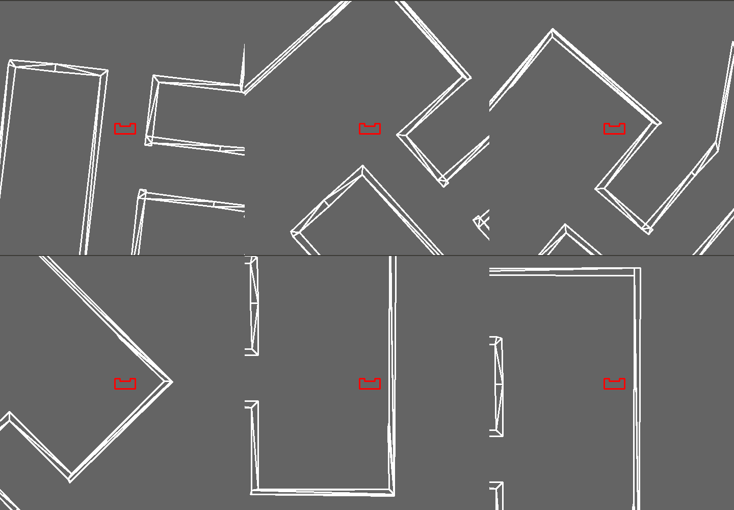
When 80% of the LRF data is larger than 1 meter PICO knows it is in a open space and therefore it starts wall hugging in order to find the exit. Pico will stop this procedure if the width of the corridor is equal or smaller than 1.5 meter, which is the maximum size of a corridor. Below a simulation can be seen for handling an open space.

Constructing virtual walls
Constructing virtual walls is an essential part of driving PICO around the maze. First individual virtual walls are constructed, by which potential corridors are blocked. This lead PICO in the desired direction. At a later stage this idea was slightly modified by computing a wall on a radius. Therefore, PICO will move more smoothly through a corner.
Crossroad
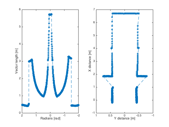
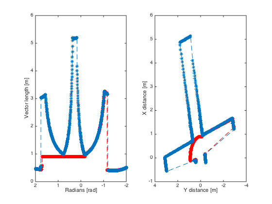
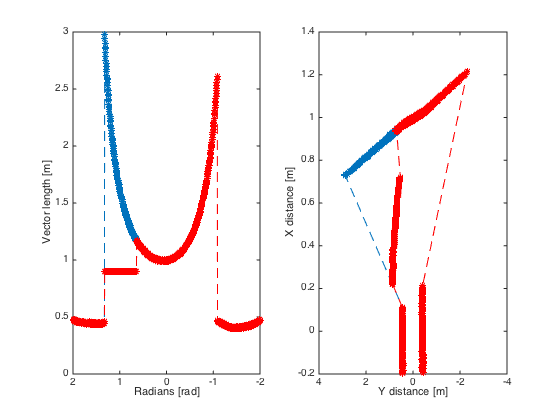
Consider a crossroad shown in the picture below. The left plot shows what PICO sees when approaching this kind of junction. There are three maxima, which represent the possible directions PICO can go in. By slightly modifying the data, the actual vision as seen in the simulator can be constructed, as shown in the figures below. In the figure on the left two minima are shown that represent the far corners between the three maxima. These provide PICO with reference points from where the virtual walls are constructed. Depending on the direction of the desired turn, the corner is used as a reference point for computing the radius at which the virtual walls are placed. In the right figure the actual constructed walls can be seen. The corridor in front and the left corridor are blocked, so due to blocking of these path ways, the potential field will lead PICO to the desired right direction.
|
T-junction
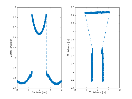
Now a T-junction is further examined. The figure below shows what PICO sees in this case. The figure shows two maxima with a minimum inbetween those maxima. These two maxima are used as bounds for finding the minimum. When the robot turns, it is hard to keep a reference point. Therefore finding this minimum is a good method of finding the reference point, which is needed to construct the virtual walls. These actual constructed wall can also be seen. In the case of a T-junction, the situation is slightly different. In this case, using the above method will not result in a minimum, that represents a corner. However locating this minimum is useful, depending on the kind of turn (100+n[minimum] or 100-n[minimum]), a radius is computed which will represent the virtual wall. These actual constructed wall can also be seen. The left corridor is blocked, so similar to the crossroad, PICO will be directed to the right corridor.
|
Door Detection
Since a door is basically a dead end which can be opened, PICO should search for dead ends. These have a specific profile where always three walls are visible and connected. Since the maze is axis aligned, two of these walls will be parallel. The other wall is positioned perpendicular to the parallel. These dead ends can be found at the end of a corridor and in junctions longer than 0.3 meters. This means PICO has to detect dead ends/doors in front and at the sides. Therefore PICO will search in three regions in its LRF-data for doors. All regions use the same methods for detecting doors. This method is based on the profile of a dead end and PICO tries to recognize dead ends by searching its LRF-data with some conditions. PICO will search for the two corner points where the walls meet. In between these corner points, the dead end/door can be detected. See the figure below, the points which PICO must detect are highlighted by a red cross. PICO will first start by searching the left corner point [1] within a certain range. If this point can be found, pico will search for the wall or door [2] which should be right of this point. If this point can be found, PICO will search for the last point which is the right corner point [3]. PICO will only look for the next point if the last one is found.
To prevent PICO from wrongly detecting doors, two extra conditions to qualify as a door/dead end are added. When the points are found, the distance to these points and the angles are known. This makes it possible to determine whether all points are aligned. This is done by calculating the distance of all points according to figure 3 as "distance to pico". All three lenghts should be approximately equal. The second condition is that the length of the door has to be within the bound given in the assignment. Thus: 0.5 < door length < 1.5. If all conditions are met, this area will qualify as a daed end/door. If the distance to PICO has become small enough, PICO has reached the door area. During the experiments we noticed that doors could still be wrongly detected due to measurement noise, or if the walls are placed a little askew. Therefore the last fix was introduced. PICO has to detect dead ends/doors ten times in a row before it actually qualifies as a real dead end/door. This is done in order to eliminate measurement noise/faults.
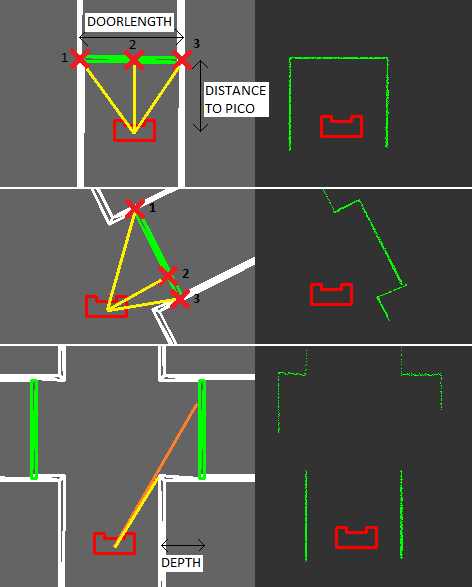
If PICO has detected a dead end/door and it is positioned in the door area, PICO will immediately stop and send the door request. After this, PICO will stand still for six seconds to wait if the doors opens. After this waiting time, PICO will look for one more second whether it is still in the door area. If PICO is still in the door area, this means that nothing has changed and the door has not opened. It will qualify these results as a regular dead end and turn around. If PICO is no longer in the door area, PICO concludes that the door has opened and PICO will continue on its path. Since this path was directed at the door, PICO will go through the door and continue the search for the exit of the maze.