PRE2022 3 Group5: Difference between revisions
No edit summary |
No edit summary Tag: 2017 source edit |
||
| Line 12: | Line 12: | ||
|- | |- | ||
|Wouter Litjens||1751808 | |Wouter Litjens||1751808 | ||
| | |Chassis & Drivetrain Specialist | ||
|- | |- | ||
|Boril Minkov||1564889 | |Boril Minkov||1564889 | ||
Revision as of 18:52, 11 February 2023
Group members
| Name | Student id | Role |
|---|---|---|
| Vincent van Haaren | 1 | Human Interaction Specialist |
| Jelmer Lap | 1569570 | LIDAR & Environment mapping Specialist |
| Wouter Litjens | 1751808 | Chassis & Drivetrain Specialist |
| Boril Minkov | 1564889 | Data Processing Specialist |
| Jelmer Schuttert | 1480731 | Robotic Motion Tracking Specialist |
| Joaquim Zweers | 1734504 | Actuation and Locomotive Systems Specialist |
Project Idea
The project idea we settled on is designing a crawler robot to autonomously create 3d maps of difficult to traverse environments so humans can plan routes through small unknown spaces
Project planning
| Week | Description |
|---|---|
| 1 | Group formation |
| 2 | Prototype design plans done
Bill of Materials created & Ordered components |
| break | Carnaval Break |
| 3 | Monday: Split into sub-teams
work started on prototypes for LIDAR, Locomotion and Navigation |
| 4 | Thursday: Start of integration of all prototypes into robot demonstrator |
| 5 | Thursday: First iteration of robot prototype done [MILESTONE] |
| 6 | Buffer week - expected troubles with integration |
| 7 | Environment & User testing started [MILESTONE] |
| 8 | Iteration upon design based upon test results |
| 9 | Monday: Final prototype done [MILESTONE] & presentation |
| 10 | Examination |
State of the Art
Literature Research
| Paper Title | Reference | Reader |
|---|---|---|
| Modelling an accelerometer for robot position estimation | [1] | Jelmer |
| An introduction to inertial navigation | [2] | Jelmer |
| Position estimation for mobile robot using in-plane 3-axis IMU and active beacon | [3] | Jelmer |
| Mapping and localization module in a mobile robot for insulating building crawl spaces | [4] | Jelmer L |
| A review of locomotion mechanisms of urban search and rescue robot | [5] | Joaquim |
| Variable Geometry Tracked Vehicle, description, model and behavior | [6] | Joaquim |
Modelling an accelerometer for robot position estimation
The paper discusses the need for high-precision models of location and rotation sensors in specific robot and imaging use-cases, specifically highlighting SLAM systems (Simultaneous Localization and Mapping systems).
It highlight sensors that we may also need: " In this system the orientation data rely on inertial sensors. Magnetometer, accelerometer and gyroscope placed on a single board are used to determine the actual rotation of an object. "
It mentions that, in order to derive position data from acceleration, it needs to be doubly integrated, which tents to yield great inaccuracy.
drawback: the robot needs to stop after a short time (to re-calibrate) when using double-integration to minimize error-accumulation: “Double integration of an acceleration error of 0.1g would mean a position error of more than 350 m at the end of the test”.
An issue in modelling the sensors is that rotation is measured by gravity, which is not influenced by for example yaw, and gets more complicated under linear acceleration. The paper modelled acceleration, and rotation according to various lengthy math equations and matrices, and applied noise and other real-word modifiers to the generated data.
It notably uses cartesian and homogeneous coordinates in order to seperate and combine different components of their final model, such as rotation and translation. These components are shown in matrix form and are derived from specification of real-world sensors, known and common effects, and mathematical derivations of the latter two.
The proposed model can be used to test code for our robot's position computations.
This paper (as report) is meant to be a guide towards determining positional and other navigation data from interia based sensors like gyroscopes, accelerometers and IMU's in general.
It starts by explaining the inner workings of a general IMU, and gives an overview of an algorithm used to determine position from said sensors' readings using integration, showing what intermitted values represent using pictograms.
It then proceeds to discuss various types of gyroscopes, their ways of measuring rotation (such as light inference), and resulting effects on measurements, which are neatly summarized in equations and tables. It takes a similar for Linear acceleration measurement devices.
In the latter half the paper, concepts and methods relevant to processing the introduced signals are explained, and most importantly it is discussed how to partially account for some of the errors of such sensors. It starts by explaining how to account for noise using allan variance, and shows how this effects the values from a gyroscope.
Next, the paper introduces the theory behind tracking orientation, velocity and position. It talks about how errors in previous steps propagate through the process, resulting in the infamously dangerous accumulation of inaccuracy that plagues such systems.
Lastly, it shows how to simulate data from the earlier discussed sensors. Notably though the previous paper already discussed a more accurate and recent algorithm (building on this paper).
Position estimation for mobile robot using in-plane 3-axis IMU and active beacon
The paper highlights 2 types of positioning determination: Absolute (does not depend on previous location) and Relative (does depend on previous location). It goes on to highlight advantages and disadvantages of several location determination systems. It then proposes a navigation system that mitigates as much of the flaws as possible.
The paper continues by describing the sensors used to construct the in plane 3 axis IMU: - x/y accelerometer, - z-axis gyroscope
Then, the ABS is described. It consists of 4 beacons mounted to the ceiling, and 2 ultrasonic sensors attached to the robot. The technique essentially uses radio frequency triangulation to determine the absolute position of the robot. The last sensor described is an odometer, which needs no further explanation.
Then, the paper discusses the model used to represent the system in code. Most notably the system is somewhat easier to understand, as the in-plane measurements mean that much of the robot position's complexity is restricted to 2 dimensions. The paper also discusses the used filtering and processing techniques such as a karman filter to combat noise and drift. The final processing pipeline discussed is immensely complex due to the inclusion of bounce, collision and beacon-failure handling.
Lastly, the paper discusses the result of their tests on the accuracy of the system, which shown a very accurate system, even when the beacon is lost.
Mapping and localization module in a mobile robot for insulating building crawl spaces
This paper describes a possible use case of the system we are trying to develop. According to studies referenced by the authors the crawl spaces in many european buildings can be a key factor in heat loss in houses. Therefore a good solution would be to insulate below floor to increase the energy efficiency of these buildings. However this is a daunting task since it requires to open up the entire floor and applying rolls of insulation. The authors then propose the creation of a robotic vehicle that can autonomously drive around the voids between floors and spray on foam insulation. There already exist human operated forms of this product, however the authors suggest an autonomous vehicle can save time and costs. A big problem with the Simultanious localization and mapping (SLAM) problem in underfloor environments according to the authors is the presence of dust, sand, poor illumination and shadows, this makes the mapping very complex according to the authors.
A proposed way to solve the complex mapping problem is by using both camera and laser vision combined to create accurate maps of the environment. The authors also describe the 3 reference frames of the robot, they consist of the robot frame, the laser frame and the camera frame. The laser provides a distance and with known angles 3d points can be created which can then be transformed into the robot frame. The paper also describes a way of mapping the color data of the camera onto the points
The authors continue to explain how the point clouds generated from different locations can be fit together into a single point cloud with an iterative closest point (ICP) algorithm. The point clouds generated by the laser are too dense for good performance on the ICP algorithm. Therefore the algorithm is divided in 3 steps, point selection, registration and calidation. During point selection the amount of points is drastically reduced, by downsampling and removing floor and ceiling. Registration is done by running an existing ICP algorithm on different rotations of the environment. This ICP algorithm returns a transformation matrix that forms the relation between two poses and one that maximizes an optimization function is considered to be the best. The validation step checks if the proposed solution for alignment of the clouds is considered good enough. Finally the calculation of the pose is made depending on the results of the previous 3 steps.
Lastly, the paper discusses the results of some expirements which show very promising results in building a map of the environment
A review of locomotion mechanisms of urban search and rescue robot
This paper investigates/compiles different locomotion methods for urban search and resque robots. These include:
Tracks
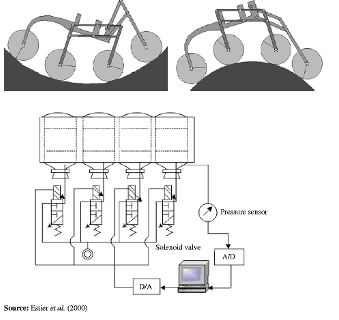
A subgroup of track-based robots are variable geometry tracked (VGT) vehicles. These robots are able to change the shape of the tracks to anything from flat to triangle-shaped, to bend tracks. This is useful to traverse irregular terrain. Some VGT-vehicles which use a single pair of tracks are able to loosen the tension on the track to allow it to adjust its morphology to the terrain (e.g. allow the track to completely cover a half-sphere surface). An example of such a can be seen below.

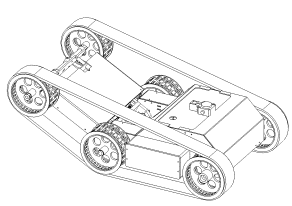
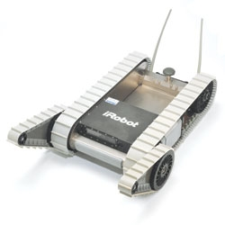
There also exist track based robots which make use of multiple tracks on each side such as the one illustrated below. It is a very robust system making use of its smaller ‘flipper’ to get over higher obstacles. Such an example is seen in the figure below.

Wheels
The paper also describes multiple wheel based systems. One of which is a hybrid of wheel and legs working like some sort of human-pulled rickshaw. This system however is complicated since it will need to continuously map its environment and adjust its actions accordingly.
Furthermore the paper details a wheel-based robot capable of directly grasping a human arm and carrying it to safety.
A vehicle using a rover-like configuration as shown below is also discussed. The front wheel makes use of a spring to ensure contact and the middle wheels are mounted on bogies to allow it to passively adhere to the surface. This kind of setup could traverse obstacles as large as 2 times its wheel diameter.

Gap creeping robots
I took the liberty of skipping this since it was mainly focussed on robots purely able to move through pipes, vents etc. which is not applicable for our purposes.
Serpentine robots
The first robot which is explored is a multiple degrees of freedom mechanical arm which is capable of holding small objects with the front and has a small camera attached there also. This being a mechanical arm means it is not truly capable of locomotion but it still has its uses in rescue work which has a fragile and sometimes small environment which a small cross section could help with. The robot is controlled using wires which run throughout the body which are actuated at its base.
Leg based systems
The paper describes a few leg based designs. First of which was created for rescue work after the Chernobyl disaster. This robot-like design spans almost 1 metre and is able to climb vertically using the suction cups on its 8 legs. While doing so, it is able to carry up to 25 kg of load. It can also handle transitions between horizontal and vertical terrain. Furthermore it is able to traverse concave surfaces with a minimum radius of 0.5 metres.
Conclusion
This paper concludes by evaluating all prior robots and their real life application in search and rescue work. This however is not relevant for autonomous crawl space scanning. Except it may indicate why none of the prior robots would be suitable for search and rescue work due to the unstructured environment and the limitations of its autonomous workings.
Variable Geometry Tracked Vehicle, description, model and behavior
This paper presents a prototype of an unmanned, grounded, variable geometry tracked vehicle (VGTV) called B2P2. The remote controlled vehicle was designed to venture through unstructured environments with rough terrain. The robot is able to adapt its shape to increase its clearing capabilities. Different from traditional tracked vehicles the tracks are actively controlled which allows it more easily clear some obstacles.
The paper starts off with stating that robots capable of traversing dangerous environments are useful. Particularly ones which are able to clear a wide variety of obstacles. It states that to pass through small passages a modest form factor would be preferable. B2P2 is a tracked vehicle making use of an actuated chassis as seen in a prior image.
The paper states that the localization of the centre of gravity is useful for overcoming obstacles. However, since the shape of the robot isn’t fixed, a model of the robot is a necessity to find it as a function of its actuators. Furthermore the paper explains how the robot geometry is controlled which consists of the angle at the middle and the tension-keeping actuator between the middle and last axes. These are both explained using a closed-loop control diagram.
Approaching the end of the paper multiple obstacles are discussed and the associated clearing strategy. I would suggest skimming through the paper to view these as they use multiple images. To keep it brief they discuss how to clear: a curb, staircase, and a bumper. The takeaway is that being able to un-tension the track allows it to have more control over its centre of gravity and allows increasing friction on protruding ground elements (avoiding the typical seesaw-like motion associated with more rigid track-based vehicles).
In my own opinion these obstacles highlight 2 problems:
- The desired tension on the tracks is extremely situationally dependent. There are 3 situations in which it could be desirable to lower the tension, first is if it allows the robot to avoid flipping over by controlling its centre of gravity (seen in the curb example). Secondly it could allow the robot to more smoothly traverse pointy obstacles (e.g. stairs such as shown in the example). Thirdly, having less tension in the tracks could allow the robot to increase traction by increasing its contact area with the ground. This context-dependent tension requirement to me makes it seem that fully autonomous control is a complex problem which most likely falls outside of the scope of our application and this course.
- The second problem is that releasing tension could allow the tracks to derail. This problem however could be partially remedied by adding some guide rails/wheels on the front and back. This would confine the problem to only the middle wheels.
The last thing I would want to note is that if the sensor to map the room is attached to the second axis, it would be possible to alter the sensor’s altitude to create different viewpoints.
- ↑ Z. Kowalczuk and T. Merta, "Modelling an accelerometer for robot position estimation," 2014 19th International Conference on Methods and Models in Automation and Robotics (MMAR), Miedzyzdroje, Poland, 2014, pp. 909-914, doi: 10.1109/MMAR.2014.6957478.
- ↑ Woodman, O. J. (2007). An introduction to inertial navigation (No. UCAM-CL-TR-696). University of Cambridge, Computer Laboratory.
- ↑ T. Lee, J. Shin and D. Cho, "Position estimation for mobile robot using in-plane 3-axis IMU and active beacon," 2009 IEEE International Symposium on Industrial Electronics, Seoul, Korea (South), 2009, pp. 1956-1961, doi: 10.1109/ISIE.2009.5214363.
- ↑ Mapping and localization module in a mobile robot for insulating building crawl spaces. (z.d.). https://www.sciencedirect.com/science/article/pii/S0926580517306726
- ↑ Wang, Z. and Gu, H. (2007), "A review of locomotion mechanisms of urban search and rescue robot", Industrial Robot, Vol. 34 No. 5, pp. 400-411. https://doi.org/10.1108/01439910710774403
- ↑ Jean-Luc Paillat, Philippe Lucidarme, Laurent Hardouin. Variable Geometry Tracked Vehicle, description, model and behavior. Mecatronics, 2008, Le Grand Bornand, France. pp.21-23. ffhal-03430328
- ↑ Paillat, Jean-Luc & Com, Jlpaillat@gmail & Lucidarme, Philippe & Hardouin, Laurent. (2008). Variable Geometry Tracked Vehicle (VGTV) prototype: conception, capability and problems.
- ↑ Paillat, Jean-Luc & Com, Jlpaillat@gmail & Lucidarme, Philippe & Hardouin, Laurent. (2008). Variable Geometry Tracked Vehicle (VGTV) prototype: conception, capability and problems.
- ↑ Wang, Z. and Gu, H. (2007), "A review of locomotion mechanisms of urban search and rescue robot", Industrial Robot, Vol. 34 No. 5, pp. 400-411. https://doi.org/10.1108/01439910710774403