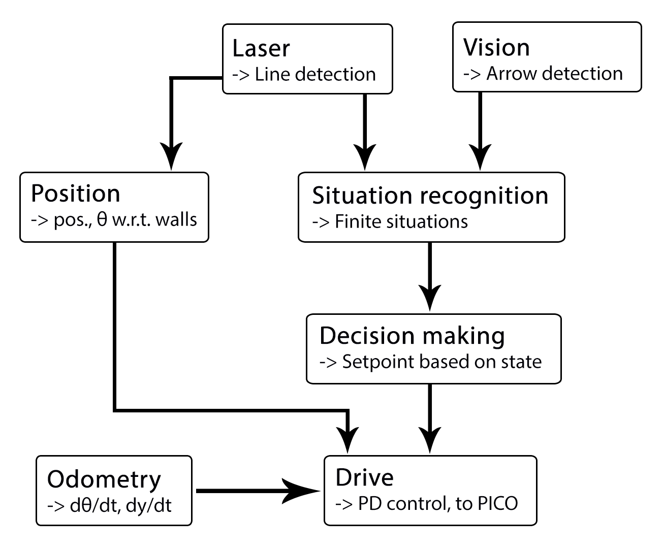
| Lines consisting out of start and end point
[math]\displaystyle{ (x1,y1),(x2,y2)\lt math\gt \lt br\gt \lt br\gt etc.
|Transformation of raw data to lines by use of hough-transform
|-
|Arrow detection
|
|Camera images
|/pico/vision
|Arrow detected to the left of the right
|Detection of arrows pointing to left or right.
|-
|Odometry
|/pico/odom
| Quaternion matrix
|/pico/yaw
|float with yaw angle
|Transform Quaternion in roll, pitch and yaw angles. Only yaw angle is send because roll and pitch are zero.
|-
|Distance
|/pico/line_detection
|Line coordinates
|/pico/dist
|(Y_left, Y_right, X, theta_left, theta_right) also named 'relative position'
|Determine distance to wall to left, right and front wall. Also determines angle left and right with respect to the walls.
|-
|Drive
|/pico/state
/pico/dist
|
dx,dy, dtheta
Y_left, Y_right, X, theta_left, theta_right
|/pico/cmd_vel
|Pico moving
|Move pico in the desired direction
|-
|Situation
|/pico/line_detection
/pico/laser
/pico/vision
|Line data, vision interpretation and possibly laser data.
|/pico/situation
|The situation where pico is in. For example corridor to the right, T-junction, etc.
|Situation parameters.
|-
|State generator
|/pico/situation
/pico/yaw
|Situation and yaw angle of Pico.
|/pico/state
|dx,dy, dtheta|Based on the situation Pico needs to go through different states and continue to drive. Every state defines an action that Pico needs to do.
|}
----
===Line detection ===
inputs: -- \lt br\gt
function: transformation of raw data to lines by use of hough-transform \lt br\gt
output: lines consisting out of start and end point (x_1,y_1),(x_2,y_2) etc. \lt br\gt
\lt br\gt
convert laser data to points (x,y)\lt br\gt
use hough transform\lt br\gt
filter lines\lt br\gt \lt br\gt
data output format: (richard + sander)\lt br\gt \lt br\gt
topic: /pico/lines\lt br\gt \lt br\gt
msg: lines\lt br\gt \lt br\gt
----
===Arrow detection ===
===Relative distance ===
input topic: /pico/lines\lt br\gt
function: Determine distance to wall to left, right and front wall. Also determines angle theta with respect to the corridor. \lt br\gt
output: (Y_left, Y_right, X, theta)\lt br\gt
output topic: /pico/dist\lt br\gt \lt br\gt
msg: dist\lt br\gt \lt br\gt
\lt br\gt
The angle theta can be calculated with the next fomula:\lt br\gt \lt br\gt
\lt math\gt \theta = atan((y2-y1)/(x2-x1)) }[/math]
the position perpendicular to the line/wall is calculated with the next formula:
[math]\displaystyle{ X_r = x2 - ((y2-y1)/(x2/x1))*y2*sin(\theta_1) }[/math]
[math]\displaystyle{ X_l = x4 - ((y4-y3)/(x4/x3))*y4*sin(\theta_2) }[/math]
theta is average of left and right or only left or right depending on situation
Drive
This node sends velocity commands to Pico based on input from the state generator node and relative position node. The state generator node sends a velocity in x and theta based on the state it is in. The relative position node sends the distance and angle relative to the left and right wall with Pico as the centre. When possiblethis information is used for the orientation and positioning of Pico.
Situation
inputs: lines, vision, relative position
Two different approaches are taken into account, a simple approach in which only is detected if the left, front and right side of pico are 'free' of walls/obstacles. But also a more elaborate approach in which situations are detected like, junctions, T-junctions, crossings and dead ends.
Lines can be categorized in two types of lines:
Longitudinal lines: y-coordinates of begin and end point are similar
Lateral lines: x-coordinates of begin and end point are similar
Situations to be recognized:
- inbetween two walls
No obstacles in front, no lateral line detected within X meter.
2 longitudinal lines are detected.
- Junction
3 lines are detected. From which two are longitudinal lines and one is lateral within (X meter).
Detect direction of juction by comparing the x -values of the longitudinal lines with the x-value of the lateral line.
Left junction: When the x value of the left line (the line with the smallest Y values) is 'minimum corridor width' smaller then the x value of the lateral line a gap on the left side is recognized.
Right junction: When the x value of the right line (the line with the smallest Y values) is 'minimum corridor width' smaller then the x value of the lateral line a gap on the left side is recognized.
- Dead end
3 lines are detected. From which two are longitudinal lines and one is lateral within (X meter).
Detect direction of dead end by comparing the x -values of the longitudinal lines with the x-value of the lateral line. When the x values of both longitudinal lines are similar to those of the lateral line a dead end can be recognized.
- T junction: 3 situations named T-right, T-left, T-right-left.
T-right: 3 longitudinal lines are detected, 1 lateral lines detected on the right side of pico.
T-left: 3 longitudinal lines are detected, 1 lateral lines detected on left side of pico.
T-right-left: 2 longitudinal lines are detected: 4 lateral lines are detected
- X junction
4 longitudinal and 4 lateral lines are detected
State generator
input: Situation, relative position
input topic: /pico/sit
function: Create setpoint for position of pico by use of state. (determine wanted position and speed).
output:
output topic: /pico/
msg:
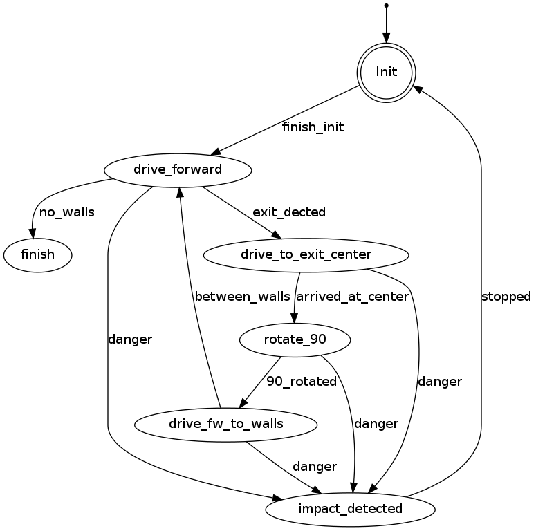
PICO states corridor challenge
For the robot, the internal states can be visualized as in the following figure:

|
 THIS FIGURE HAS TO BE ADAPTED!!!
