Embedded Motion Control 2014 Group 1
Group Info
| Name: | Student id: | Email: |
| Groupmembers (email all) | ||
| Sander Hoen | 0609581 | s.j.l.hoen@student.tue.nl |
| Marc Meijs | 0761519 | m.j.meijs@student.tue.nl |
| Wouter van Buul | 0675642 | w.b.v.buul@student.tue.nl |
| Richard Treuren | 0714998 | h.a.treuren@student.tue.nl |
| Joep van Putten | 0588616 | b.j.c.v.putten@student.tue.nl |
| Tutor | ||
| Sjoerd van den Dries | n/a | s.v.d.dries@tue.nl |
Meetings
Time Table
Fill in the time you spend on this course on Dropbox "Time survey 4k450.xlsx"
Planning
Week 1 (2014-04-25 - 2014-05-02)
- Installing Ubuntu 12.04
- Installing ROS
- Following tutorials on C++ and ROS.
- Setup SVN
- Plan a strategy for the corridor challenge
Week 2 (2014-05-03 - 2014-05-09)
- Finishing tutorials
- Interpret laser sensor
- Positioning of PICO
Week 3 (2014-05-10 - 2014-05-16)
- File:Presentatie week 3.pdf
- Starting on software components
- Writing dedicated corridor challenge software
Week 4 (2014-05-17 - 2014-05-25)
- File:Presentatie week 4.pdf
- Finalize software structure maze competition
- Start writing software for maze competition
Week 5 (2014-05-26 - 2014-06-01
- Test first maze competition software in practice
- Determine bottlenecks for maze competition
- Start with arrow detection
Software architecture
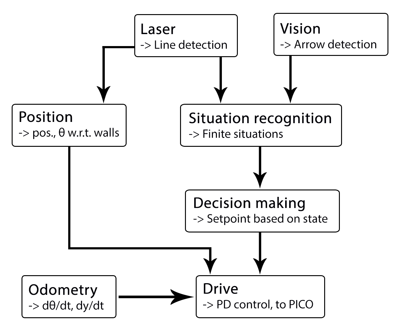
We decided to use a architecture as seen as the following figure:

The components with their respective functions and in and outputs are listed here + who wil work on it:
| node | subscibes topic: | input | publishes on topic: | output | Description |
| Line detection - Sander | - | laser scan | /pico/line_detection | lines consisting out of start and end point (x_1,y_1),(x_2,y_2) etc. | transformation of raw data to lines by use of hough-transform |
| Position - Richard | line coordinates | (X_left, X_right, Y, theta) also named 'relative position' | Determine distance to wall to left, right and front wall. Also determines angle theta with respect to the corridor. | ||
| Arrow detection | camera | Arrow left of right | determine if pico sees an arrow and in what direction. | ||
| state recognition - Joep | lines, vision, relative position | an integer of whitch state is recognized | recognize situation and transform this to one of the states. | ||
| setpoint generator - Wouter | state, relative position | speed and position | Create setpoint for position of pico by use of state. (determine wanted position and speed). | ||
| Drive - Marc | setpoint, relative position | x,y,thata (Moving pico) | make sure that pico is positioned centered if this is needed and turn when needed.
|
Line detection - Sander
inputs: --
function: transformation of raw data to lines by use of hough-transform
output: lines consisting out of start and end point (x_1,y_1),(x_2,y_2) etc.
convert laser data to points (x,y)
use hough transform
filter lines
data output format: (richard + sander)
topic: /pico/lines
msg: lines
relative distance - Richard
input topic: /pico/lines
function: Determine distance to wall to left, right and front wall. Also determines angle theta with respect to the corridor.
output: (Y_left, Y_right, X, theta)
output topic: /pico/dist
msg: dist
The angle theta can be calculated with the next fomula:
[math]\displaystyle{ \theta = atan((y2-y1)/(x2-x1)) }[/math]
the position perpendicular to the line/wall is calculated with the next formula:
[math]\displaystyle{ X_r = x2 - ((y2-y1)/(x2/x1))*y2*sin(\theta_1) }[/math]
[math]\displaystyle{ X_l = x4 - ((y4-y3)/(x4/x3))*y4*sin(\theta_2) }[/math]
theta is average of left and right or only left or right depending on situation
Drive - Marc
inputs: setpoint, relative position
function: make sure that pico is positioned centered if this is needed and turn when needed.
outputs: (Moving pico)
Situation - Wouter
inputs: lines, vision
Lines can be categorized in two types of lines:
Longitudinal lines: y-coordinates of begin and end point are similar
Lateral lines: x-coordinates of begin and end point are similar
Situations to be recognized:
- inbetween two walls
No obstacles in front, no lateral line detected within X meter.
2 longitudinal lines are detected.
- Junction
3 lines are detected. From which two are longitudinal lines and one is lateral within (X meter).
Detect direction of juction by comparing the x -values of the longitudinal lines with the x-value of the lateral line.
Left junction: When the x value of the left line (the line with the smallest Y values) is 'minimum corridor width' smaller then the x value of the lateral line a gap on the left side is recognized.
Right junction: When the x value of the right line (the line with the smallest Y values) is 'minimum corridor width' smaller then the x value of the lateral line a gap on the left side is recognized.
- Dead end
3 lines are detected. From which two are longitudinal lines and one is lateral within (X meter).
Detect direction of dead end by comparing the x -values of the longitudinal lines with the x-value of the lateral line. When the x values of both longitudinal lines are similar to those of the lateral line a dead end can be recognized.
- T junction: 3 situations named T-right, T-left, T-right-left.
T-right: 3 longitudinal lines are detected, 1 lateral lines detected on the right side of pico.
T-left: 3 longitudinal lines are detected, 1 lateral lines detected on left side of pico.
T-right-left: 2 longitudinal lines are detected: 4 lateral lines are detected
- X junction
4 longitudinal and 4 lateral lines are detected
State generator - Joep
input: Situation, relative position
input topic: /pico/sit
function: Create setpoint for position of pico by use of state. (determine wanted position and speed).
output:
output topic: /pico/
msg:
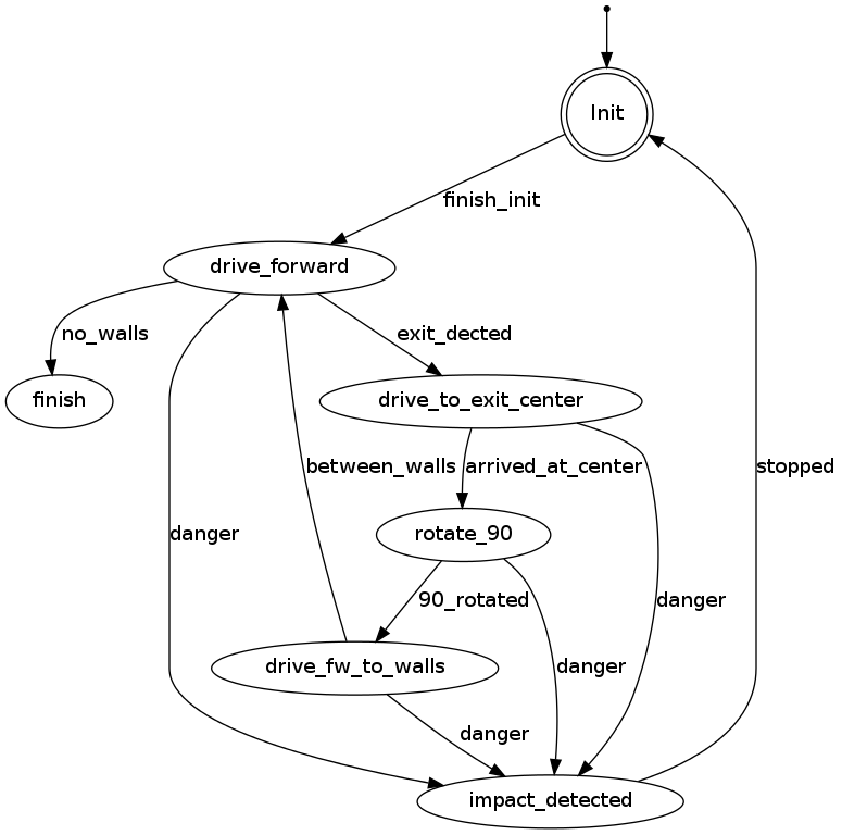
PICO states corridor challenge
For the robot, the internal states can be visualized as in the following figure:
