SolidWorks Casing
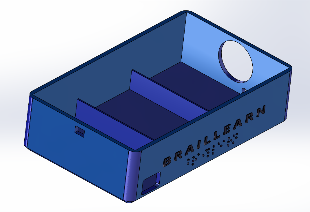
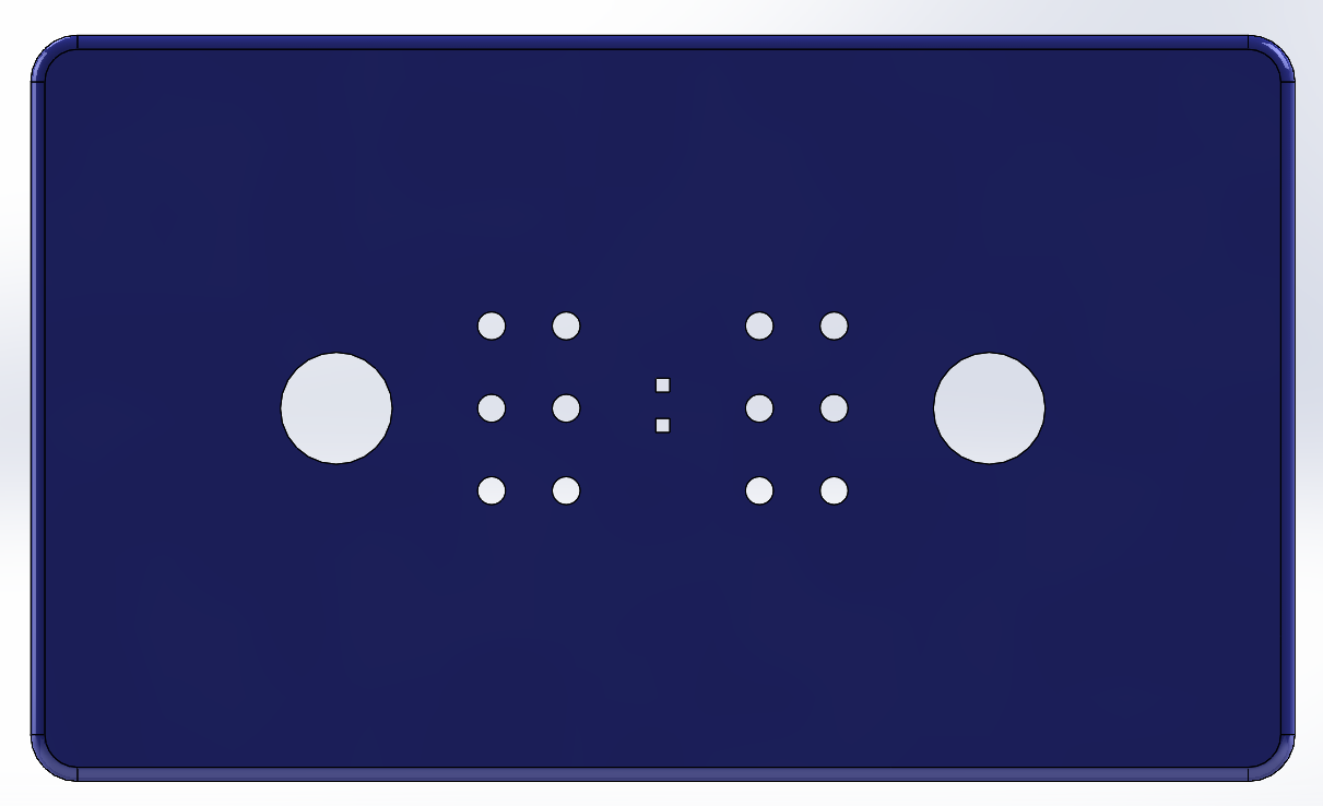
The casing that will be used for the final design has been made in SolidWorks. Due to the broad available literature regarding SolidWorks, this was the most viable option. The final design, and its subparts (case and lid), are depicted in the images to the right.
In the final design, the dimensions L x W x H are much larger than the estimated dimensions for the crude approximation, namely being 220 x 110 x 75 mm. This is due to the fact that an external power supply has to be added that can deliver 7 A. Also the solenoids take much more place than estimated to reduce the total cost, since the tiny braille cells are quite expensive.
Another thing that might be noticeable is that the holes have not been added for the solenoids and the headphone input. This has been done deliberately, since these dimensions might be subject to change throughout the design. Therefore it is better to drill these holes ourselves when all the component placements are known inside the casing.


