Embedded Motion Control 2013 Group 7
Approach to be used:
Strategy -> Software architecture -> Work division -> Test
Group members
Jordy Senden, 0716539, j.p.f.senden@student.tue.nl, Mechanical Engineering, NL
Erik van Broekhoven, 0637413, e.c.v.broekhoven@student.tue.nl, Mechanical Engineering, NL
Luigi Corvino, 138588, l.corvino@student.tue.nl, Mechatronics Engineering, IT
Martin Huberland, 131492, m.huberland@student.tue.nl, Mechanical Engineering, BE
Marcello Di Giandomenico, 138554, m.digiandomenico@student.tue.nl, Mechatronics Engineering, IT
Tutor: Jos Elfring
Meeting #1 - 9/9/2013
Topic:
- Introducing with group members (Background, C-knowledge)
- Installed required software / solved software issues
- Refreshing C language knowledge
- Started to work on the tutorials
- Set-up a meeting with our tutor
- Set standard meeting days on monday and thursday afternoon
Meeting #2 - 12/9/2013
- Meeting with our tutor
- Installed gazebo software
- Solved remaining software issues
To do before next meeting: read the ROS concepts on the EMC website.
Meeting #3 - 16/9/2013
- Thinking about strategies for the corridor competition
Meeting #4 - 18/9/2013
- Concluded the work on the strategy
- Started implementing some basic functionalities
- RECAP 18/9/2013
Meeting #5 - 30/9/2013
- Decide once for all the modular software architecture
- Choose modules, nodes, inputs and outputs to split the work (30/9)
- Think about a initialization function that corrects PICO's orientation.
- Think about a function that restores the motion after an avoided collision from the safety measures.
- Choose the maze solving strategy
- Choose between the simplest approach, i.e. right wall following, and the most complex one, SLAM.
- Split up the group according to the required functionalities of PICO
Meeting #6 - 7/10/2013
- Started working on new line detection algorithm
- Started working on image acquisition
- Started working on decision making node
Meeting #7 - 14/10/2013
- Tried to combine the three different nodes
- Solve the problems due to functions overlapping and make the first tests on Gazebo
- Definition of the new wall-following and safety-condition functions
- Organization of the last details before the next test on Pico
Strategies
Corridor competition
For the corridor we decided to develop a simple code, possibly recyclable for the maze navigation. This deadline is a required step in order to really get our hands dirty and acquire some familiarity with C++ programming and ROS.
It's imperative for the robot to stay approximately in the middle of the corridor, which has been divided into a safe zone and a dangerous zone. PICO compares two distances measured from the laser scans and based on their difference it corrects its orientation by rotating to the left or to the right. During this rotation a small forward velocity is fed to the base in order to get a smooth movement. When he detects the exit, he starts the turning maneuver.
At first, the turning was composed by both linear and angular displacements, but in the end we decided to change our turning method. The exit detection algorithm remained the same, while the turning maneuver changed into a turn on the spot movement as the previous one's success ratio wasn't so high: it was common for PICO to hit the walls if the corridor was too narrow, since the turn was a simple open loop one. Comparing the scan ranges, PICO is able to compute the distance to the exit center and the exit amplitude, so we use some counters in the code in order to define exactly the time needed to reach the wanted position by sending appropriate calibrated velocity commands. In this way PICO's movements depend on the environment and should not allow him to hit the walls.
The Competition(25/09)
We used our "safe" code: not the fastest, but we were nearly sure that PICO would find the exit. In fact, he managed to within 38 seconds. This gave us the 4th place. Unfortunately we had no time to test efficiently the code on PICO in order to achieve higher velocities. We still have a lot of work to do, but this result was really encouraging. Here is a little view of the competition: https://vimeo.com/75465839. A remark has to be done, though: we won't share our beers with PICO anymore. As it's clearly visible from the video, he was drunk.
Maybe the fault is ours, since the wall following algorithm has to be improved!
Maze solving
After the corridor competition we decided to spend one week trying the different solutions proposed during a brainstorming. In order to solve the maze, two main different approaches can be used: a complex one, involving real time map building, localization and path planning, and a simple one, involving wall following and easy decision making.
For the first approach, different tools already exist: for instance, rviz+Navigation stack.
Jazz robot comes with complete compatibility with ROS. For further information: Gostai Open Jazz.
In the beginning, for the second approach we thought about developing the corridor competition strategy, but after some work on it we understood that is really difficult to achieve our goal in this way, in fact in the maze there are different configurations to be aware of, and using this code everything can be compromised by the smallest error. Our exit detection needs to scan the next wall with a 30° angle at least and so cannot be accurate because of the various wall lenghts and gaps.
The simplest, but quite efficient strategy (on paper) we decided to adopt is the right wall following with the aid of camera's arrow detection. This won't let us achieve the fastest time in the final competition, but has a certain robustness (the maze has no islands, and following the right wall will lead PICO to the exit for sure, in absence of failures) and it's easier to implement, thus avoiding waste of time and resources in trying to understand difficult concepts about SLAM.
We opted to use a modular structure with different ROS nodes (see Software architecture). In this way, we can focus on basic programming problems and on software modularity. We decided to use four ROS nodes even if some say that this is not useful, not because we want to complicate our job but to help us understand how ROS nodes work. Basically, our robot must be able to detect different types of junctions and move accordingly. The goal is thus very simple at first glance, and could be handled by using a "blind navigation" approach towards the environment (the walls), consisting in reading the local information about the surroundings with the laser and acquiring and processing images to help PICO find his way. Solving algorithms, like Trémaux, will be implemented only if we have time.
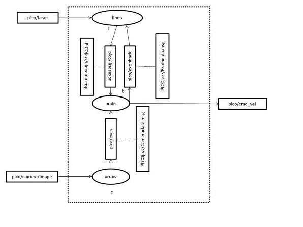
Writing the code, we realized that the number of nodes could be reduced. We decided to keep the decision making node, a.k.a. the brain, alongside the line/corner detection node and the image processing node.
Line detection node
The idea is the following: we are going to robustly implement two functions in this node:
- to know accurately the PICO's position w.r.t. both right and left walls, therefore we'll be able to stand in the middle of the corridor for most of the time;
- to find out which is the 1st horizontal front wall, and to compute the distance from PICO to this one.
To do so, we are going to loop infinitely over many functions described below:
- laserCallback(): this function saves all the laser scanned points and plot them in an image, and saves the front, left and right distances to the wall;
- laserToPoints(): this function applies the Hough Transform to figure out the beginning and end points of each line detected. The next step is to sort the lines according to their position and orientation into 4 categories. Finally, we compute the distance to the closest wall;
- checkFreePaths(): this function checks, if we are closed to the first horizontal front wall, if there is any free path to the left, right or in front of PICO;
- sendToBrain(): this fucntion is used to send only the relevant datas to the brain node.
Polar conversion
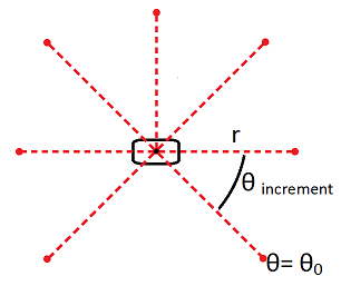
The output from the laser range finder are discrete points in space. These points represent a distant to an object (r) at a certain angle (θ) with respect to PICO. Once the angle of the first point and the angle increment of the sensor is known, each measured point can be represented in polar coordinates (θ,r). In the figure below, a representation of this is given.
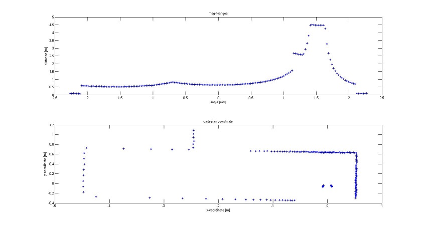
However, when we want to analyse PICO’s position with respect to surrounding object, the polar representation is not really efficient. This can be made clear with the following figure [EMC2012 group7]. The top picture of this figure is a representation of the laser points in the polar coordinates. From viewing this top graph, it is not immediately clear where the walls are with respect to PICO’s position (θ,0). The bottom picture represents the same points, but translated to Cartesian coordinates. It becomes immediately clear where the walls are. Now PICO is at the origin (0,0). The few points close to r=0 in the top picture and (0,0) in the bottom picture are the laser points which are reflected by PICO’s own body.
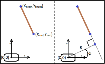
The first step has been made to identify the walls. However, the wall still only exist as a series of points. For the robot it is not clear when a wall begins or ends. It is also not clear if the walls are “vertical” or “horizontal” with respect to PICO. Vertical wall are parallel to PICO’s driving direction while horizontal walls are perpendicular to this direction. This distinction is necessary because horizontal walls may cause head on collisions while vertical walls may in their turn be useful to drive straight. It is decided to make an algorithm which provide us with a line representation of the walls. This representation can exists of a start point and endpoint of the line in Cartesian coordinates, or the orientation of the line can be given in polar coordinates. Where the distance R represents the shortest distance of the wall to PICO and the angle φ represents the lines orientation with respect to PICO (figure).
TO DO!! Explain purpose; advantage/disadvantage.
First tactic, point-to-point evaluation
Explain how we first wanted to do this, but decided not to
Second tactic, Hough transform
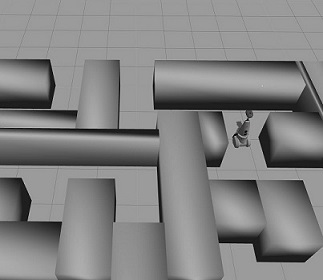
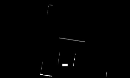
Because the poin-to-point evaluation might be prone to errors, it is decided to take another tactic. Our tutor pointed to us that within OpenCV there exist a function which searches for lines in pictures. This function would be useful to detect the arrow with the camera, but could also be used to detect the lines from the sensor data. However, the function uses an image as input, while the points are represented by values for x and y. To solve this problem, either the Hough transform function can be adapted, or the data points need to be converted into an image. It is decided to do the later because the Hough function already works. Adapting it to our problem could lead to troubles. To transform the data points into an image, we use the cv::imwrite function in OpenCV which transforms a matrix into an image. Each entry in this matrix will correspond to a pixel in the image. All the entries have a grayscale value from 0 to 255 or a colour representation of [r,b,g] where r,b and g also can have a value from 0 to 255. For our purpose it is sufficient to work with the grayscale values. First it is necessary to define a matrix of size (r,c). The r and c represent the number of rows and columns respectively and are determined by the range of ‘sight’ of PICO’s laser. For instance, if we want to look 5 meter in each direction with centimetre accuracy, the matrix will be of size (1.000,1.000) . All values in this matrix are set to 0, or black in the image. Next, all the laser data points are evaluated. The x and y value of every point corresponds to an entry in the matrix. At this entry, the value is set to 255, or white in the image. An example of this can be seen in the next figures. The first picture shows a simulation of PICO in a maze. The next black and white picture shows the data points from PICO’s laser, transformed into an image. It can be seen that the image is not a square. This is because the matrix which is constructed is also not a square. It was decided that the range of sight on the back of the robot does not need to be equal to the front range. PICO can detect object in front of him from a further distance than objects at his back. The white rectangle in the bottom centre is a representation of PICO itself.
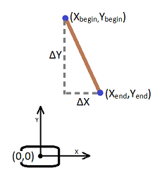
From this image the lines may be detected using the Hough transform function. The problem with this function is its robustness. The function might detect multiple lines on one wall. In order to cope with this problem, the lines are divided into four different types; left or right vertical walls and front or back horizontal walls. At first, a distinction needs to be made between horizontal and vertical walls. This is done using the difference between the points of the line. If ΔX is bigger than ΔY, the line is considered to be of the horizontal type. If it is the other way around, the line is of the vertical type.
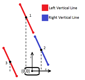
The next thing to investigate, is the side on which the lines exist; left/right or front/back. To show how this is done, the left/right vertical walls are discussed. The distinction between front and back in the horizontal case is done in the same fashion. The first idea of checking whether the walls were of type right vertical or left vertical, is described in the picture below. An average X is calculated using Xbegin and Xend; Xavg=(Xbegin+Xend)/2. This X corresponds to a point in the middle of each line. By evaluating whether or not this Xavg is bigger of smaller than the X of PICO’s position, the type of the wall would be known. This works well if PICO is nearly perfectly aligned. The picture below shows what happens when PICO is askew in a long wall.
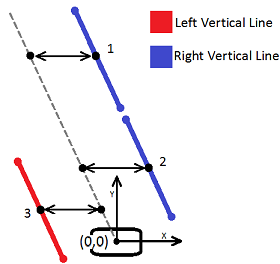
As can be seen from the picture, this algorithm is very robust. Line 1 is supposed be a line of type Right Vertical but is now recognized as a left line. This is because the average X is smaller than PICO’s position. This error can occur when the wall are far away and the robot is not aligned with the walls. To cope with this, the vertical lines have to be evaluated with respect to the middle of the corridor. A visualization of this is given in the next figure.
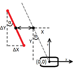
To do this evaluation, the points on the middle of the corridor (grey dotted line) need to be found. It is decided to take points at the same height as the points of the lines, i.e. the Y values are the same. The difficult part is to get the X value of the points on the dotted line. For this, the orientation of the lines with respect to PICO needs to be known. In other words, one angle of the lines need to be known. It does not matter which angle is calculated, as long as the angle is used properly. Because ΔX can become very small, or even zero, if PICO is aligned to the wall, it is decided not to use the quotient between ΔX and ΔY to calculate the angle. This quotient could become zero or infinite. Therefor it is decided to take the length of the line piece instead. This will be made clear in the next figure. In this figure, only one wall is given to explain the method.
Now, the length of the line piece is calculated as: L=sqrt(ΔX¬2 + ΔY2)
Angle α is than given by: α = acos(ΔY/L)
Point X on the middle of the line can then be calculated as: X = tan(α)*Y
Where Y is corresponds to some Y on the evaluated line. Now, every X on the line piece should be smaller or bigger than its corresponding X on the dashed line to be a left or right wall respectively. It suffices to only evaluate one X on the line piece, for instance Xbegin or Xend. This algorithm is more robust. The next figure shows the distinction between left or right vertical walls and front of back horizontal walls. The difference between horizontal and vertical is shown with the thickness of the lines. The distinction between left or right and front or back is made clear with either a white or grey colour.
Now that the line are separated into four different types, they can be used to navigate PICO through the maze. For instance, if no horizontal walls are detected, PICO needs to just drive straight ahead. As soon as a front horizontal wall is detected, this means that a junction is ahead. The distance to this junction can be estimated and PICO can drive up to the middle of this junction. Using the vertical walls and the previously calculated α, PICO could align himself to the walls. Furthermore, the difference in distance between the left and right wall gives PICO a measure whether he is on the centre line or not.
Functions
Brain node
This node merges the information sent by camera topic and from the line detection node so to turn in the right way. In order to stay in the center of the corridor the brain tries to keep the difference betweeen the right and left radius from the line detected as low as possible.
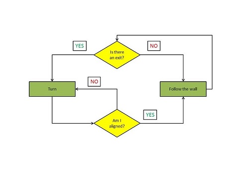
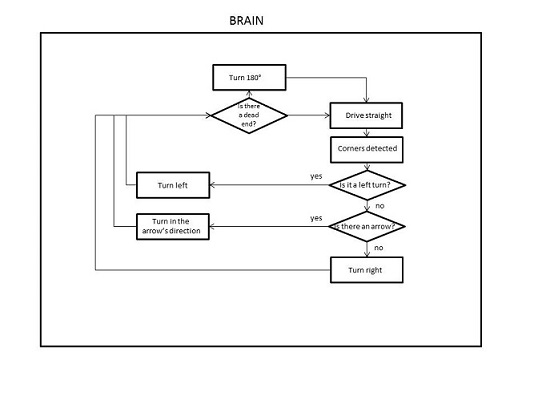
In a first time we opted for this flow-chart scheme, but when we started to implement it we realize that was too untidy for our purposes and we changed to an easier pseudo-code, focused in exploiting as much as possible our line detection algorithm. In this original algorithm the priority was to read the camera information; if there's none, turn right if possible. In case of dead end, turn 180° and keep following the right wall.
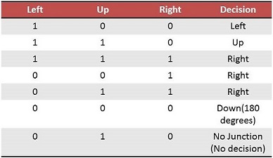
In the new approach, PICO always follows the right wall, until he detects an opening in the corridor. This is possible by reading the boolean data sent from the line detection node: one to stop and three for the junctions.
- cross=true when PICO reaches the center of a cross junction, thanks to the line detection data we can manage to stop in the center of the corridor, and then decide where to go.
- left,up,right=true when PICO recognizes an opening in the specified direction.
After elaborating all these data PICO can decide where to turn, always in agreement with the right wall following. Only in the T-junction case PICO has to check the directives coming from the camera topic.
Filling a matrix with the possibles case PICO can easy understand where is possible to go:
The lines node also send one more boolean variable for the safety condition:
- drive=true Pico can drive because is in a safety zone.
Also the scan ranges needed for the wall following and the dead end zone are sent from the lines node, these are an avarage of the North, Right and Left scan.
Functions
- The turning function is the same of the corridor competition: a time counter with a loop that allows to achieve the desired angle with the selected velocity, thus 90° for normal turning and 180° when PICO is in a dead-end point.
- The wall following function has been recycled from the corridor competition and has to be improved if possible.
Arrows detection
...
Functions
Software architecture
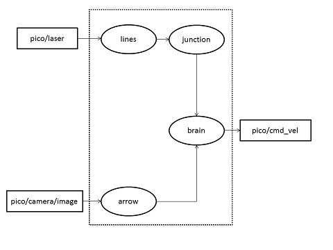
A first rough structure of our software can be represented in the following image:
We decided to change it and reduce the number of nodes, since not all of them are strictly necessary. We defined our custom messages as well.
We still have to test the efficiency of such a system.
Work division
We decided to divide the work such that noone wastes important time.
- Eric -> Image acquisition, Camera and everything concerned with the arrow detection
- Jordi -> Line detection algorithm and Junction recognition
- Martin -> Line detection algorithm and Junction recognition
- Marcello -> Software architecture, inputs/outputs, custom messages, nodes
- Luigi -> working on previous algorithm, brain node and taking exit using the Right Wall following method
Tests
First test (19/9)
Experiments are performed on PICO, however the testing did not go as planned. PICO had to be resetted sometimes and did not respond to our commands as expected. The data shown in the terminal however, did show the proper values while running.
Second test (20/19)
We experienced again some connection issues. We were able to move the robot, and again some delay seemed to occur. The discharged batteries have put a premature end to our tests.
Third test (24/9)
We had 15 minutes to verify our new code, developed in a few hours of this very day, that allows PICO to turn on the spot. Everything worked fine, but improvements have to be made to get a more robust algorithm and, most of all, a fastest one: the turning maneuver is too slow.
Fourth test (11/10)
In this test we used the ROS record function in order to check in different situations what PICO can elaborate from his sensors and from the camera thanks to our line detection and arrow detection algorithm. We recorded in various .bag files the only three topics in which we were interested: camera,laser and odom. Now we can work in this week-end to improve our codes with the real data.
Possible Problems
During our real tests and the simulations we realize that something can always go wrong. Even though we try to achieve a very efficient robustness the robot can behave in an unexpected way. Some noticeable examples are related to the Pico's movements, they don't correspond exactly to our commands, probably this is because of the friction of the wheels and the non-idealities of the environment. We computed how to turn accurately to 90° and 180° using the command velocity, anyway we obtain often an error of about 2 degrees. We are not able to control this imprecision with our functions so we decided to overcome it only after the turning function has been completed using the wall-following function.
A different issue is due to the safety condition. We don't want Pico to crash against the wall, so for emergency cases we need it to stop. We have not handled yet how to solve this problem, so how to make Pico come back in a reasonable position to continue his path. Unfortunately when Pico is so close to the walls, situation that normally doesn't have to happen using our wall-following function, Pico suddenly stop and finish his run! We hope that Pico will not need to use this safety function!
The first three loop scan_ranges give back only 0 values. Actually we don't know why and we decided to exclude these values from some functions, like the turning 180 for the dead end because they were overlapping its operations.
Always regarding the scan ranges we don't use the first and last 30 scans of every loop because the first 7 laser scan hit Pico's body and overcome our working, we decided to discard other few values to maintain a certain security extent.
After combining the brain and lines nodes we discover to have various problems, the two nodes overlapped with different decisions at the same time, this happened during the turning and cross detection. We managed to overcome these problems sending back from the brain some messages to the lines such that this last node can understand at which point of the brain code we are.
