Embedded Motion Control 2018 Group 6
Group members
| Name: | Report name: | Student id: |
| Thomas Bosman | T.O.S.J. Bosman | 1280554 |
| Raaf Bartelds | R. Bartelds | add number |
| Bas Scheepens | S.J.M.C. Scheepens | 0778266 |
| Josja Geijsberts | J. Geijsberts | 0896965 |
| Rokesh Gajapathy | R. Gajapathy | 1036818 |
| Tim Albu | T. Albu | 19992109 |
| Marzieh Farahani | Marzieh Farahani | Tutor |
Initial Design
Link to Initial design report
The report for the initial design can be found here.
Requirements and Specifications
Use cases for Escape Room
1. Wall and Door Detection
2. Move with a certain profile
3. Navigate
Use cases for Hospital Room
(unfinished)
1. Mapping
2. Move with a certain profile
3. Orient itself
4. Navigate
Requirements and specification list
In the table below the requirements for the system and their specification as well as a validation are enumarated.
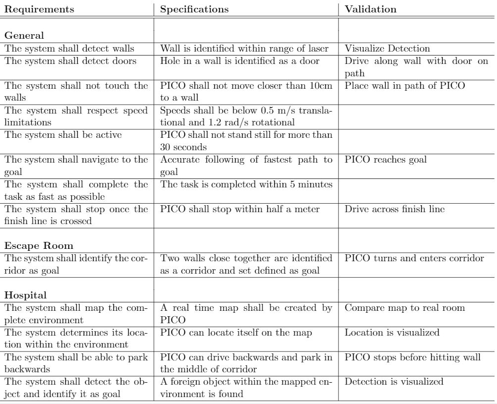
Functions, Components and Interfaces
The software that will be deployed on PICO can be categorized in four different components: perception, monitoring, plan and control. They exchange information through the world model, which stores all the data. The software will have just one thread and will give control in turns to each component, in a loop: first perception, then monitoring, plan, and control. Adding multitasking in order to improve performance might be applied in a later stage of the project. Below, the functions of the four components are described. What these components will do is described for both the Escape Room Challenge (ERC) and the Hospital Challenge (HC).
In the given PICO robot there are two sensors: a laser range finder (LRF) and an odometer. The function of the LRF is to provide the detailed information of the environment through the beam of laser. The LRF specifications are shown in the table bellow,
| Specification | Values | Units |
| Detectable distance | 0.01 to 10 | meters [m] |
| Scanning angle | -2 to 2 | radians [rad] |
| Angular resolution | 0.004004 | radians [rad] |
| Scanning time | 33 | milliseconds [ms] |
At each scanning angle point a distance is measured with reference from the PICO. Hence an array of distances for an array of scanning angle points is obtained at each time instance with respect to the PICO.
The three encoders provides the odometry data (i.e) position of the PICO in x, y and &theta directions at each time instance. The LRF and Odometry observers' data plays a crucial role in mapping the environment. The mapped environment is preprocessed by two major blocks Perception and Monitoring and given to the World Model. The control approach to achieve the challenge is through Feedforward, since the observers provide the necessary information about the environment so that the PICO can react accordingly.
Interfaces and I/O relations
The figure below summarizes the different components and their input/output relations.
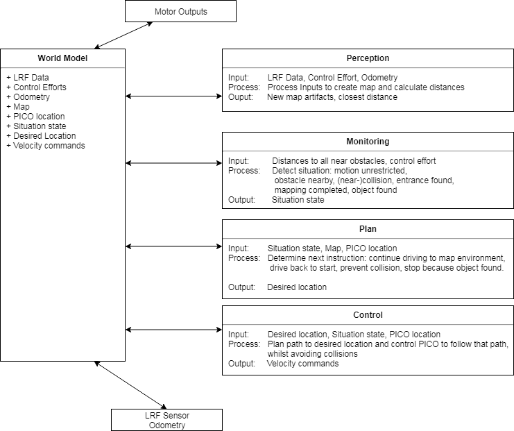
Overview of the interface of the software structure:
The diagram below provides a graphical overview of what the statemachine will look like. Not shown in the diagram is the case when the events Wall was hit and Stop occur. The occurence of these events will be checked in each state, and in the case they happened, the state machine will navigate to the state STOP. The state machine is likely to be more complex, since some states will comprise a sub-statemachine.
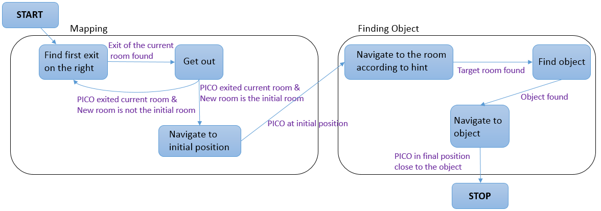
Program structure
Worldmodel The world model contains the prior knowledge that is available as well as information about the surroundings of PICO. It is in the world model that the perception function stores the treated data from the laser rangefinder. Furthermore, it contains a big matrix representing the map where PICO is. This matrix is updated at each time step. Initially, all the values are unknown (represented by -1), then the values are replaced by 100 for known occupied space and 0 for known free space. This method allows for easy path planning by means of Dijkstra or A*. This matrix data can be used to create semantics for the map. From the matrix, doors, rooms, and the corridor can be classified by clever treatment of the data. A drawback of this matrix created by gmapping is that prior knowledge is not implemented. For example, sometimes the walls measured by mapping are not entirely straight or the corners are not exactly orthogonal. This makes treatment and recognition from the data harder.
Perception: In perception, the sensor data is processed. First, the data that measure distances smaller than 10 cm are filtered out, these are instances where the laser finder sees PICO itself. Then the distances and the angles are used to turn each data into cartesian coordinates. Lastly, 3 points on the left of the robot are used to check for alignment with the wall.
Monitoring Map complete Location driving: In this part of the code a
Planning
Map until known space is enclosed
drive to start
bump into wall at start
map again+ compare to the previous map
drive to object
Control
follow wall better follow trajectory drive backwards
Gmapping
For the hospital challenge, the initial state of the environment (i.e. the hospital corridor and the rooms) has to be stored in some way. This can be done in various ways, one of which is mapping. By initially mapping the environment, all changes can be detected by comparing the current state of the environment to the initial mapped environment. Mapping itself can also be done in many ways. One commonly used method is SLAM (Simultaneous Localization and Mapping), SLAM maps the environment and simultaneously improves the accuracy of the current position based on previously mapped features. There are a lot of SLAM algorithms available, one of which is a ROS package called Gmapping. This Gmapping package uses a ROS node under the name of slam_gmapping that provides laser-based SLAM [1].
The library used by this ROS package is the library from OpenSlam [2]. The herein developed approach uses a particle filter in which each particle carries an individual map of the environment. Since the robot moves around, these particles get updated information about the environment to provide a very accurate estimate of the robot's location and thereby the provided map.
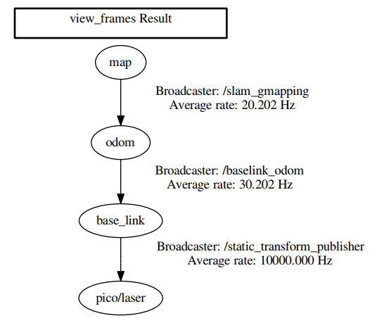
Gmapping requires three transitions between coordinate frames to be present, one between the map and the odometry, one between the odometry and baselink and one between baselink and the laser. Gmapping provides the first transition but the remaining two have to be developed. The second transition has to be made by a transform broadcaster that broadcasts the relevant information published by the odometry. The final link is merely a static transform between the baselink and the laser and can thereby be published via a static transform publisher. These transforms are made using TF2 [3]. An overview on the required transformations can be requested using the view_frames command of the TF2 package, which is shown in Figure X.
Gmapping definitely has various limitations, such as:
- Limited map size
- Computation time
- Environment has to stay constant
Result:
Getting gmapping to work within the emc framework took quite some effort, but as seen below: it works!


Escape Room Challenge
A simple code was used for the escape room challenge. It is a code that follows a wall. The idea is as follows: Once started PICO first drives in a straight, stopping 30 cm from the first encountered wall. Once this wall detected PICO aligns it's left side with the wall and starts following the wall. Once PICO is following the wall it is testing in each loop if it can turn left, if it can't checks if it can drive forward. If it can't drive forward, meaning that it reached a corner, it will start turning right until it is aligned with the wall in front of it. Then it starts the loop again. This application is very simple but it is robust. Due to the simple geometry of the room, the code should be sufficient for the simple task of getting out.
In the following section, more details are given about the different components of the code (perception, modeling, plan, control, world model, main)
The world model is a class with all the information stored inside. The other components, perception, modeling, plan and control function which are called at a frequency of 20 Hz by the main loop.
- Perception
- Monitoring
- Plan
- Control
Result:
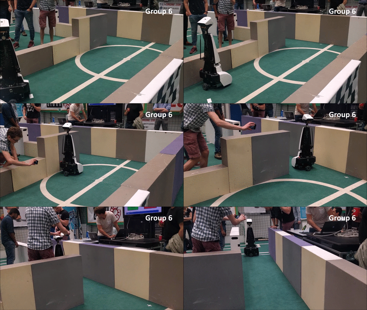
Merely two teams made it out of the room, one of which was us! We also had the fastest time so we won the Escape the Room Challenge!
Hospital challenge
Architecture
Gmapping
Activity Log
An overview over the meeting, activity's and planning can be found at: https://www.overleaf.com/read/vjgrrdnfzhtp