|
|
Viotar project group
William Schattevoet
David Duwaer
Eric Backx
Arjan de Visser
|
|
|
|
|
|
|
Design 0.1
On friday the 5th of november, the first attempt at a design was finished. Only geometric constraints were taken into account, meaning the size of the engines and actuators were solely adjusted to the amount of space that was available in the guitar.
|
 
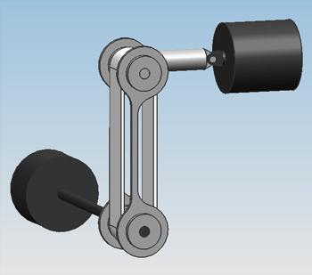
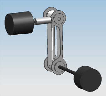
The bowing mechanism for a single string in Design 0.1. A motor at the bottom (black) drives the bowing belt (white), which is pushed against the string by an actuator at the top (black), with a spring shaft in between.
|
|
 
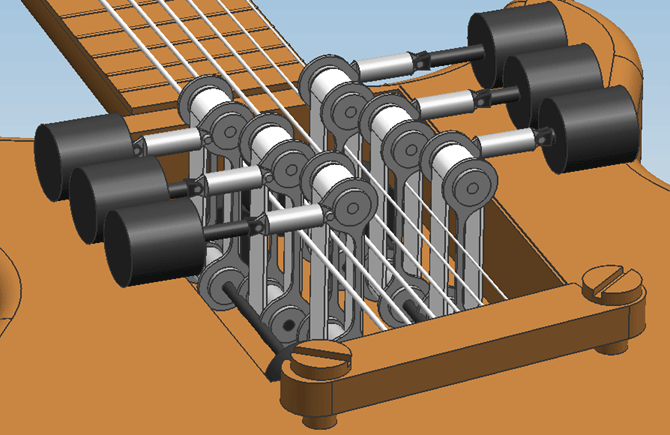
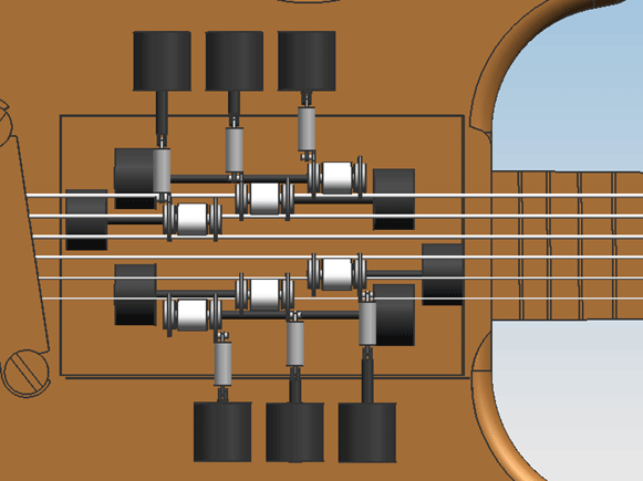
The assembly of all six bowing mechanisms in the guitar in Design 0.1. With this spacial configuration, only little space is left for the motors that drive the belt. Also, the mechanism is very wide in the direction of the strings, and positioned unnessarily far from the neck, leaving too little space for the strings to be plucked by hand.
|
Design 0.2
From reviewing design 0.1 with the group, the following points of improvement were determined:
- There is too little space for the engines, so their spacial configuration should be altered so that they can be bigger.
- There shouldn't be motors on the neck side of the construction, because that forces the construction towards the bridge, leaving less space for the player to pluck the strings.
- An estimation should be done on the size of the motors, based upon an estimation of the power that is required from them.
These improvements have been worked into design 0.2.
Estimation of the required motor power
The needed motor power is calculated using [math]\displaystyle{ P=M_{T}*\Omega }[/math]. For this, the total load [math]\displaystyle{ M_{T} }[/math] and the angular speed [math]\displaystyle{ \Omega }[/math] should be calculated.
The total motor load consists of the load coming from the friction of the bowing belt with the string [math]\displaystyle{ M_{w} }[/math] and the friction of the bearing supporting the wheel that drives the belt, [math]\displaystyle{ M_{br} }[/math].
[math]\displaystyle{ M_{w} }[/math] is calculated by [math]\displaystyle{ M_{w}=R\cdot F_{w}=R\cdot F_{n}\cdot \mu_{w} }[/math], with [math]\displaystyle{ F_{n}=F_{b} }[/math] the normal force between the bowing belt and the string. This equivalent bow force has a maximum of [math]\displaystyle{ 4 N }[/math]. The value of [math]\displaystyle{ \mu_{w} }[/math] is estimated at a rather high [math]\displaystyle{ 0.7 }[/math]. The radius [math]\displaystyle{ R }[/math] of the wheel over which the belt runs is taken to be [math]\displaystyle{ 10 mm }[/math], in practice it will be smaller than this.
[math]\displaystyle{ M_{br} }[/math] is calculated assuming cylindrical roller bearings will be used. For cylindrical roller bearings [math]\displaystyle{ M_{br} }[/math] equals [math]\displaystyle{ F\mu_{w}d/2 }[/math], with [math]\displaystyle{ mu_{w}=0.002 }[/math] the friction coëfficient for cylindrical roller bearings, [math]\displaystyle{ F }[/math] the force on the bearing, and [math]\displaystyle{ d }[/math] the shaft diameter, which is about [math]\displaystyle{ 4 mm }[/math] for a bearing with a outer diameter of [math]\displaystyle{ 11 mm }[/math].
Geeft als schatting van de ordegrote:
M_r=30*0.002*4/2=0.12Nmm
Aangezien de lagers een straal hebben van nooit meer dan 10mm word de wrijvingskracht in de lagers nooit hoger dan 1 [N]. Voor 2 lagers komt de absoluut maximale kracht dan op 2 [N]. De totale kracht die de motor dan moet kunnen leveren is dan ongeveer gelijk aan 16[N], dit is dan wel de kracht bij stationair toerental.
Rotatie-energie lager:
E=1/2 J_z (φ^2 ) ̇,J_z=1/2 mr^2 geeft samen:E=1/4 mr^2 (φ^2 ) ̇=1/4*0.0017*〖0.01〗^2*300*2*π=8*〖10〗^(-5)
Dat is dus niet heel veel (een lager weegt 0.0017 kg volgens skf).
M_w=3.2*10=32Nmm,M_tot=32+0.12=32Nmm
P=M_T∙Ω=0.032*300=10 W
[math]\displaystyle{
\operatorname{erfc}(x) =
\frac{2}{\sqrt{\pi}} \int_x^{\infty} e^{-t^2}\,dt =
\frac{e^{-x^2}}{x\sqrt{\pi}}\sum_{n=0}^\infty (-1)^n \frac{(2n)!}{n!(2x)^{2n}}
}[/math]
|


