Embedded Motion Control 2015 Group 8
Group Members
| Name: | Student id: | E-mail: |
| Ruud Lensvelt | 0653197 | g.lensvelt@student.tue.nl |
| Stijn Rutten | 0773617 | s.j.a.rutten@student.tue.nl |
| Bas van Eekelen | 0740175 | b.v.eekelen@student.tue.nl |
| Nick Hoogerwerf | 0734333 | n.c.h.hoogerwerf@student.tue.nl |
| Wouter Houtman | 0717791 | w.houtman@student.tue.nl |
| Vincent Looijen | 0770432 | v.a.looijen@student.tue.nl |
| Jorrit Smit | 0617062 | j.smit@student.tue.nl |
| René van de Molengraft | Tutor | m.j.g.v.d.molengraft@tue.nl |
Design
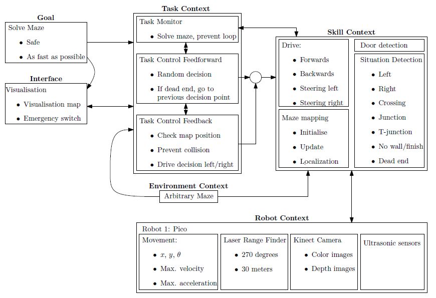
As a start of the course the initial design of the software is discussed. The design is divided into several parts, the general flow chart for the software design is shown in Figure 1.1. In the upcoming sections the initial design will be described.
-
Figure 1.1: Flow chart of the software design
Requirements
The goal of the maze-challenge is to solve the maze as quick as possible and without any collisions. As quick as possible is defined as solving the maze within a minimum amount of steps. The maze can be divided by discrete blocks, so every block is one step in solving the maze. The requirements to fulfill this goal are:
- The robot has to drive, which means movement in the x-, y- and theta-direction.
- The robot has to take boundaries into account to avoid a collision with walls or running into objects.
- The robot has to recognize doors to be able to found the exit of the maze.
- The robot has to be prevented from searching the same area twice, so a map of the maze will be constantly updated to be able to efficiently solve the maze.
Functions
The functions are divided into two groups: the general robot skill functions and the general robot task functions. First the three general robot skill functions are described.
- Drive functions
Realize motion of the robot by providing data to the robots actuators. Realizing the specified motion should be done using a controller to meet the requirements regarding safety.
Input: location set point. Output: motion of robot.
- Detection functions
Characterize different types of corridors based on telemetry provided by the Laser Range Finder.
Input: measured x, y and theta; Output: type of corridor.
- Mapping functions
Updates and maintains a map of the explored maze. These mapping functions can be used to check and visualize the robots actions and set new objectives.
Input: current x, y and theta of the robot; Output: new entry maze map or new robot objective.
Now the three general robot task functions are described.
- Feedback functions
Realize preventing the robot from collisions and check the position in the map to maintain safety requirements and to determine the desired new position in the maze.
Input: current x, y, theta, LFR data and objective; Output: motion of robot.
- Decision functions
Determine which direction or action the robot should take based on the map and current position.
Input: current x, y, theta and position in the map; Output: drive function initiated.
- Monitor functions
Control the exploration of the maze and prevent the robot to explore the same area more than once.
Input: current x, y and theta of the robot; Output: previous unexplored cross
The maze is viewed as a tertiary search tree in which paths represent the branches. Initial path search is done random with no particular preference for a direction and upon hitting a dead end, backtracking is initialized. Backtracking means the robot turns around at a dead end and returns to the previous decision point in the explored maze (map), meanwhile searching for a door. Upon detecting a door or reaching the point of the previous decision the robot continues its random search, or chooses the only unexplored direction at that particular point.
Components
The relevant components in the maze challenge are divided into two parts: the robot itself and the maze as the environment of the robot.
Relevant components of the robot
- Three omniwheels which make it possible to move the robot in x-, y- and theta-direction.
- Laser Range Finder to be able to detect the environment of the robot.
Relevant components of the maze
- Static walls which are the basis of the maze, those walls can form corners, crossings, T-junctions and dead ends.
- Doors which open automatically and make it possible for the robot to get access to the whole maze. Closed doors cannot be distinguished of the wall.
Specifications
Note: Almost all specifications have yet to be determined in specific numbers.
Driving speed specifications
It is unlikely that the maze can be completed with a fixed velocity. Therefore, a number of conditions need to be composed which specify the velocity and acceleration at each encountered situation. Velocity and acceleration may vary on the chosen strategy, for example to find a door (which implies a low velocity or even a drive-stop implementation) or the random walk.
- Random walk to explore an unknown part of the maze.
- Returning from a dead end to the previous decision point, meanwhile searching for a door.
- Detection of an intersection.
- Taking a particular intersection.
Changing direction
The robot can change its direction in different curvatures, at this moment the decision is made to make a full stop before the robot starts rotating. For this action the angular velocity and acceleration need to be specified.
- Determined: make a full stop before changing direction.
- Determined: change direction on a junction when the middle of the junction is reached.
- The angular velocity and acceleration during a rotation need to be specified.
Safety specifications
It is very important that the robot completes the maze without hitting the walls or running into objects. To prevent this, a safety specification should be implemented, which basically comes down to a minimal distance the robot has to maintain to its surroundings.
Laser Range Finder specifications
The Laser Range Finder has a maximal range of 30m. In order to complete the maze successfully, it is expected that this range is too large. The laser range specification to complete the maze has to be determined experimentally.
Interfaces
Regarding the interface, the obtained map from the maze should be visualized for convenient debugging of the code. Paths covered only once should be marked black. In addition, if a given branch does not lead to the exit, the robot will return to the last decision point. The path covered twice due to returning to the last decision point will be marked red.
To prevent unwanted behavior of the robot due to bugs in the software, a kill switch should be implemented in the interface such that the robot can remotely be switched off.
Composition Pattern
Under construction.
Initial software for corridor competition
In the initial design of the software the general framework of functions provided in Figure 1.1 is translated into a composition pattern to solve the corridor challange. The initial software consists of the robot context, skill context and task context. The skill context can be divided into two skills, the 'Drive in maze' and 'Feature detection'. The 'Drive in maze' ensures that PICO can move between the walls in the direction of a given setpoint. The 'Feature detection' detects openings in the maze, like junctions. The 'Task control' get information about the features and determines a setpoint for the 'Drive in maze' function. This software is used to complete the corridor challenge.
Robot context
Under construction
Drive in maze
Under construction
Potential field
Drive Function Block
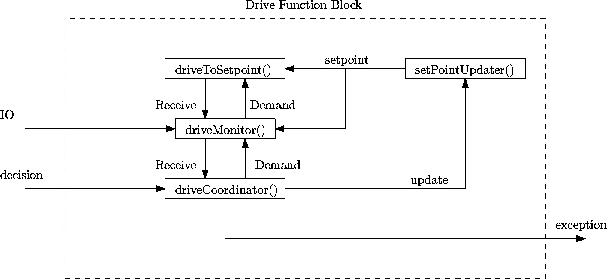
Since the required action on a junction is either one of three cases, i.e. drive straight, left or right, a general drive function blocks have been implemented who’s framework can be reused for other functions. Thus though the function of a drive function block may vary on depending on its goal, their overall composition is similar as the composition pattern provided in Figure 2.1. In Figure 2.1 the composition pattern is shown for a general drive function block and communication to its environment is provided through:
- Robot data provides the data the robot measures through its LRF and odometry sensors.
- Decision provides the decision from the globalCoordinator().
- Exception allows the drive function block to communicate to the globalMonitor() if an exception.
Depending on the decision variable provided a drive function block turns either on or stays off. When a drive function block finishes its task or finds a condition which is outside its task description it sends an exception through the Exception variable. The general drive function block consists of four distinct parts:
- driveCoordinator() verifies whether the current situation corresponds to the required action in the decision variable, i.e. when driving straight only a straight corridor is detected, otherwise it communicates to the globalMonitor() through the exception variable. The coordinator is always vigilant on a potential command from the globalCoordinator().
- setPointUpdater() adjusts the global setpoint to compensate for the robots travelled distance the setpoint. For a detailed explanation see the next section.
- driveToSetpoint() implements the actual motion towards a setpoint using the potential field, while constantly detecting changes in the robots environment.
- driveMonitor() receives data from the setPointUpdater() and driveToSetpoint() and determines the robots current location, orientation and compares what the robot actually sees against the previously provided setpoint.
Feature detection
Under construction
Task control
Under construction
Drive functionality
Setpoint when Driving straight
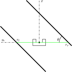
When the robot needs to drive straight, its setpoint is initially set to the front. However, Pico will not be perfectly aligned with the walls on both sides and will not perfectly drive in the middle of those walls. To keep the right orientation and to keep the robot in the middle of the corridor throughout the challenge,the setpoint needs to be be updated. In Figure 2.2, the situation is shown when the robot is not aligned. The orientation of the robot is shown in cartesian coordinates. Under the assumption that the walls are straight, the position and orientation of these walls can be estimated with a first order polynomial approximation. This approximation is obtained using a least squares method using 20 datapoints on each side. For both sides, the distance [math]\displaystyle{ r_l }[/math] to the wall on the left side and the distance [math]\displaystyle{ r_r }[/math] to the right are determined, as well as the orientation [math]\displaystyle{ \theta }[/math]. Now, the setpoint can be updated in y-direction using these data and some basic geometric knowledge. To make the system more robust against noise, the data are averaged over the last 10 iterations. This results however in a system which reacts slower to changes in the environment. In combination with the driving function that was used, some tests showed there was too much overshoot resulting in an unstable system. Therefore, the amount of correction in [math]\displaystyle{ y }[/math]-direction was scaled with a gain with an absolute value between 0 and 1.
Setpoint when Driving a corner
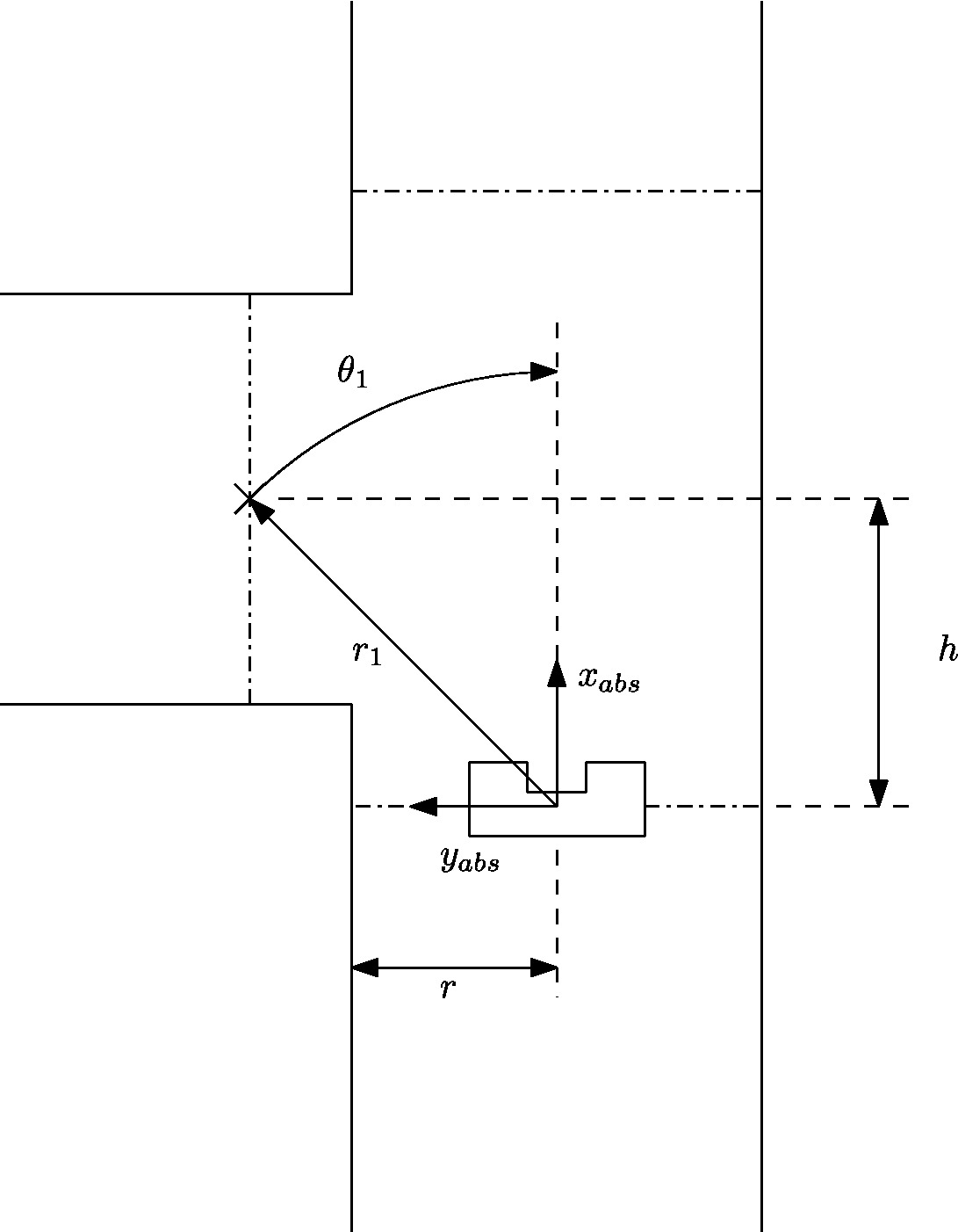
By default the robot assumes it’s in a straight corridor and upon reaching a junction the robot it switches from the drive function block to a turn block. Before a turn can start a global setpoint is determined consisting of logging the distance to its current walls, the opening of the exit of the turn and the distance to the middle of a junction. With this data it constructs a global setpoint which is used in the both the configurator driveToSetpoint() and coordinator driveCoordinator(). Furthermore, to determine the distance travelled to the setpoint a marker is dropped as soon as a cornering action is required. The initial starting point of a turn can be seen in Figure 2.3.
Since the robot’s coordinate frame is relative, the previously determined global marker is used to determine the travelled distance and the robot’s orientation. With this data the global setpoint is translated to the robot’s relative frame according to
[math]\displaystyle{ r_2=r_1-dr, }[/math]
[math]\displaystyle{ \theta_2=\theta_1-d\theta. }[/math]
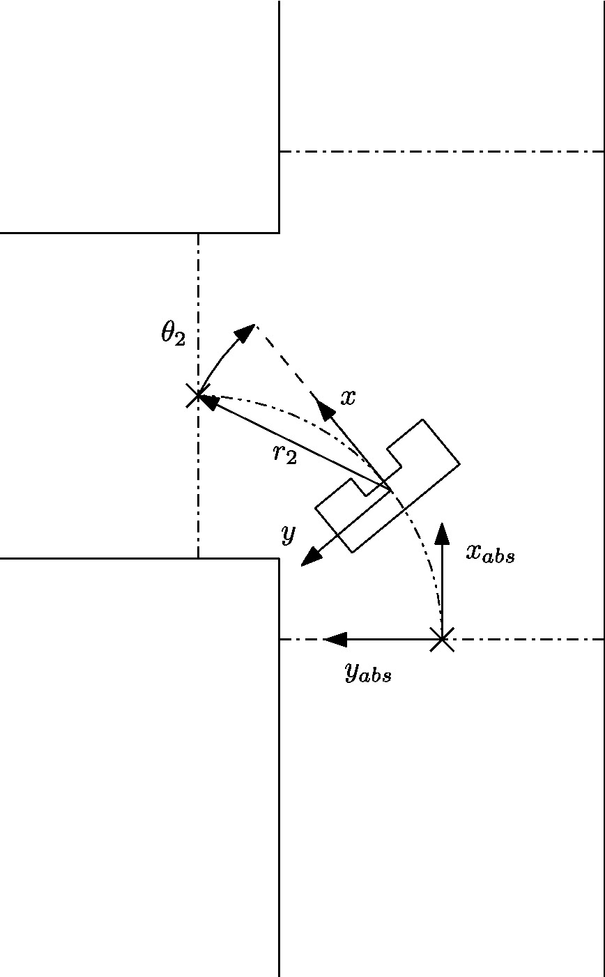
The effect of this update is that the setpoint varies in position when observing it from the robot while it stays at the same location with respect to the absolute frame. An intermediate step in driving through a corner can be seen in Figure 2.4.
To compensate for disturbances in measurements the robot is required to approach the setpoint to within a certain tolerance value tol. Since the potential field prevents the robot from driving through a wall, only the y-position of the setpoint is used to determine if a turn is completed, i.e.
[math]\displaystyle{ |y-\Delta S_y|\lt tol. }[/math]
Furthermore, by only using the y direction to determine if a turn is completed we take into account different locations of exiting the corner and the robot thus stops turning when we cross the line through the setpoint, as can be seen in Figure 2.4.
Evaluating corridor challenge
PICO managed to finish the corridor challenge. With a time of 21 seconds, we finished at the fourth place. The potential field ensures that PICO did not bump into walls, the corner of the exit was detected and PICO take this corner. However, PICO did not take the corner in a smooth way, because the setpoint in the exit was not at a fixed place. This error is solved after the competition.
Further improvements:
- The function setPointUpdater needs to be updated with LRF data. In the old version the odometry data was used.
- During the corridor competition a fixed gain was used to increase the length of the resulting force of the potential field. This gains needs to be replaced by a function that is dependent on the width of the corridor.
Software for maze challenge
Feature detection
Door handling/detection
Maze mapping/strategy
Determine orientation of the robot
Since the maze is constructed out of corners of 90 degrees, an integer multiple of this value is used to determine the orientation of the robot. The initial orientation is zero degrees, hence the decision at every subsequent junction is added to the initial orientation value. A counter clockwise structure has been applied, resulting in +90 degrees for a left turn, +180 degrees for going back the same path as the driving direction, +270 degrees of a right turn and +0 degrees for straight ahead driving over the junction. When the orientation value is larger or equal to 360 degrees, 360 degrees is subtracted. By keeping track of the orientation at every corner and junction, the orientation relative to the initial orientation is known at all times.
Determine orientation number
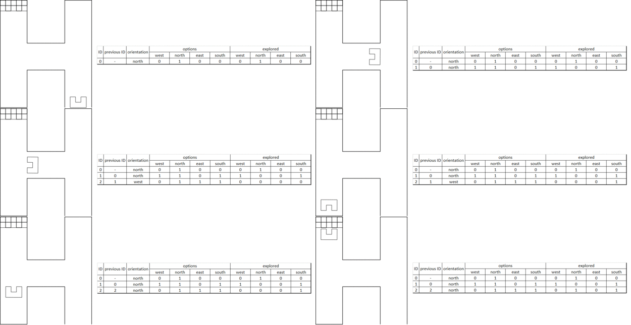
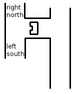
The driveMonitor() function indicates if a change in the maze is detected. It also communicates what type of situation is detected, for example a T-junction. However, the situation is communicated relative to the current driving direction, so for example if the driveMonitor() outputs a T-junction with left en right possibilities, it is possible that it actually is a T-junction in north and south direction. This situation is depicted in Figure 2.5. To obtain usable data for the maze history, the information from the driveMonitor() function is corrected with a correction number, which basically shifts the driveMonitor() information a given amount of places. The number of shifts is determined by the current orientation from the get_orientation() function: 1 for a current orientation of +90 degrees, 2 for a current orientation of +180 degrees, 3 for a current orientation of +270 degrees and 0 for a current orientation of 0 (360) degrees. Now all the junctions can be mapped in global wind direction names: North, East, South and West.
Maze history
The maze history is a vector of classes. Each entry of the vector belongs to a node ID number. Because of the work done in the orientation determination functions above, the maze history function is a matter of bookkeeping. It all starts with a detected change in the maze from the driveMonitor() function, which triggers the following actions:
- Only when the [math]\displaystyle{ 1^{st} }[/math] node is detected: Initialize first node by setting the south exploration value of the [math]\displaystyle{ 1^{st} }[/math] junction to explored. This implies that the initial driving direction is from south to north, regardless of the ´real´ direction.
- A node is added to the history vector by the push_back functionality for each detected change in the maze. This results in an expanding history vector. In each entry the coordinates of the node are saved together with information regarding the available possibilities, e.g. west, north, east and/or south opening. Next, for a new node, the exploration options are initialized. Now the current options for the junction at hand is returned to the Tremaux algorithm, e.g. the unexplored possibilities are returned.
- When a next node is created because of a change in the maze is detected the explored options from the previous node based on the decision made by the Tremaux algorithm are updated.
A graphical presentation of the maze history in action is depicted in Figure 2.6.
