Embedded Motion Control 2015 Group 5
Group Members
| Name: | Student id: |
| Bart van Willigen | 0770142 |
| Joost Peters | 0747630 |
| Robin Loose | 0771575 |
| Koen Bos | 0763939 |
| Joost Franssen | 0824821 |
| Lotte de Koning | 0655209 |
| Marjon van 't Klooster | 0819200 |
Software design assignment
The software design assignment can be found here.
Corridor challenge
Goal: Lead PICO as fast as possible through a corridor with an unknown junction. The first side exit at the junction should be taken.
Approach
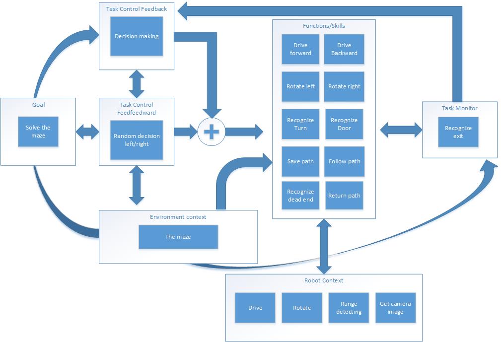
After a first succesful brainstorm, the first draft of the system interface is determined. In this schematic the different contexts are presented. The goal to solve the maze is monitored by the Task monitor. Based on the observed environment and the maze solving algorithm, a set of skills is selected. Task control feedforward is used when no deterministic choice can be made. These skills are based on the robot's basic functions.
Development
Main
Tasks
- Aligning and centering the robot:
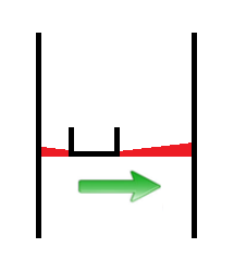
In order to drive straight and centered in a corridor, a function is created which aligns and centers the robot w.r.t. the corridor walls. The function consists of two parts; a part that uses two beam bundles on each side of the robot and compares their length in order to center the robot (Figure left), and a part that uses three small beam bundles on one side of the robot to align it with the walls. A safety check is implemented to make sure the robot ignores cracks in the corridor walls. A proportional controller is implemented for correcting the robot’s misalignment, this means that the more the robot is off-center or misaligned, the larger the control action will be to correct this.
Implementation in corridor challenge: When implementing the function for the corridor challenge, two issues arose: the proportional control could lead to problems when the system stability was compromised. Extreme high gain would result easily into a crash. A second issue was compatibility with the rotate function; during rotation at the corner, the alignment function interfered and this resulted into unwanted effects. A reason for this could be our main algorithm that consisted of a switch-case construction that was far from optimal. During the corridor challenge the align-part was disabled in order to complete the challenge.
- Recognize junction
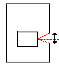
The robot is able to robustly distinguish cracks from junction. If the laser on the left or right of the robot detects a large distance, a bundle of lasers around the perpendicular laserbeam is analyzed. The angle between the first and last bundle with a large distance is calculated and this angle, combined with the corresponding distances at the outer beams of the bundle, is used to calculate the width of the crack (or junction).
- [math]\displaystyle{ width\_crack = sin(angle\_ crack/2)*distance[outer\_ bundle]; }[/math]
This width is now used to distinguish small cracks from actual junctions in the corridor.
- Take a turn:
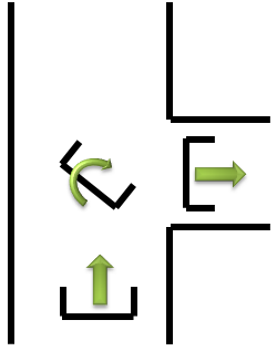
When a decision is made to turn left or right some skills will be performed. First PICO is positioned in the middle of the junction, with the skill: junction_mid. Then PICO will rotate on his position around his axis with the function rotate and after this PICO will drive forward until it is in the corridor. When two walls are detected next to him the center function will take over and will drive further until the exit is detected. These different skills are described below.
 |
 |
 |
 |
Skills
- Center at junction
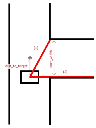
When a junction is detected and the decision has been made to enter a specific corridor, the function ‘junction_mid’ is started. The goal of this function is to stand still at the exact middle (target) of the corridor which is about to be entered. To find this exact middle, the beam to the opposing corner of the entrance is measured (1) as soon as beam (2) passes the corner. Beam (1) can then be used to compute the width of the corridor (corr_width) and therefore, the middle of the corridor is also known. Junction_mid ends when it has reached the half width of the corridor (target).
- Rotate
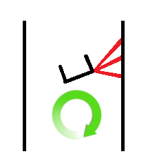
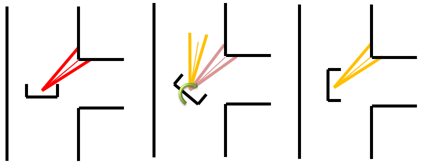
The rotation for the corridor challenge is based on the form of the corner of the wall. As example the right rotation will be used as explanation. First the corner is detected through analyzing the laser bundle at the right side of PICO, the shortest vector bundle is used as reference for the corner. For a 90 degrees rotation it can be calculated which vector bundle is needed at the left side of PICO. PICO will rotate until the vector bundle at his left side is equal to the reference vector bundle. See the rotate figure below.
- Detect exit
This function is constantly checking if the exit of the maze is reached. The LRF data is divided into ten bundles and if all of these bundles each show an average distance larger than 1.5 m, the exit of the maze is reached. In this case, the robot stops and the program is ended.
 |
 |
Conclusion
See the video of the corridor challenge!