Implementation MSD19
After a comprehensive understanding of the problem, it was divided into sub-categories to assess and work efficiently and to have a modular system as a deliverable. Following milestones were set up to keep the project on track and achieve the desired goals step by step.
- Hardware Assembly and manual flight of the drone
- Autonomous Flight of the drone
- Localization of the drone
- Path Planning of the drone
- Setting up of visualization environment
- Perception system for the drone
- Integration of sub-systems
- Testing
Getting started with Crazyflie 2.X
Crazyflie is the mini-drone which we used during this project. The positive aspect of Crazyflie is that a considerable amount of research is available online with guidelines to undergo autonomous flights. Considering the scope of this project and economical viability, Crazyflie was a good choice. Getting started section will cover the following main headings:
- Manual Flight
- Autonomous Flight
- Modifications
- Troubleshooting
A recommendation in the start would be to follow the procedure from manual to autonomous flights. Jumping directly into autonomous flight mode would is not advised as it would create a lot of ambiguity and lack of understanding of how the basic system works.
Manual Flight
This section explains in details on how to set up a Crazyflie 2.X drone starting from hardware assembly to first manual flight. We used Windows to continue with the initial setup of the software part for manual flight. However, Linux (Ubuntu 16.04) is preferred for the autonomous flight. The following additional hardware is required to set up a manual flight:
- Bitcraze Crazyradio PA USB dongle
- A remote control (PS4 Controller or Any USB Gaming Controller)
This link was used to get started with assembly and set up the initial flight requirements.
NOTE: It must be noted that the Crazyflie is running on its latest firmware. The steps to flash the Crazyflie with the latest firmware are discussed here.
The Crazyflie client is used for controlling the Crazyflie, flashing firmware, setting parameters and logging data. The main UI is built up of several tabs, where each tab is used for specific functionality. We used this link to get started with the first manual flight of the drone and to develop an understanding of Crazyflie Client. Assisted flight mode can be used to have a stable altitude and hovering as an initial manual testing mode.
Autonomous Flight
To get started with autonomous flight, the pre-requisites are as follows:
- Loco Positioning System: Please refer to “Loco Positioning System Section” for more details. The link explains the whole setup of the loco-positioning system.
- Linux (Ubuntu 16.04)
- Python Scripts: We used autnomousSequence.py file from the Crazyflie Python library. We found this script to be the starting point of autonomous flight.
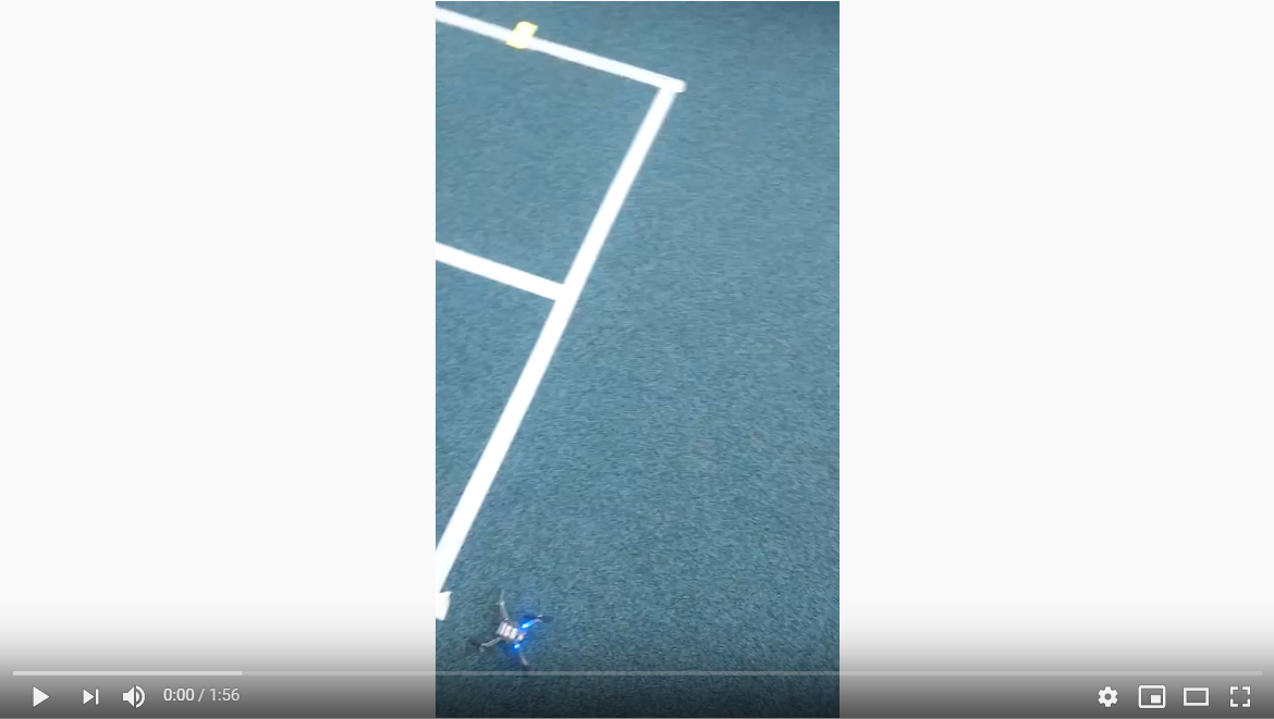
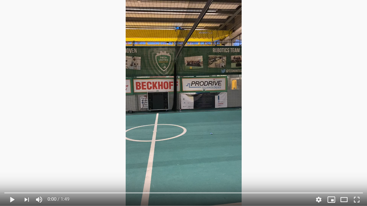
This link was also used to develop a comprehensive understanding of autonomous flight. After setting up the LPS, modifications in the python script of autonomousSequence.py file were made to adjust it according to desired deliverables. The video below shows the Crazyflie hovering autonomously while changing yaw over time.
Modifications
The following modifications were made in the autonomousSequence.py file.
- Ball Position Extraction from Visualizer Data
- Development of Path Planning Algorithm which takes the Visualizer data and converts it to drone position data
- Drone Position data extraction and sending it to Visualizer for visual representation
The modified_autonomousSequence.py file was developed in parallel with the project. The modifications were made as we were progressing through the project and new observations and suggestions were coming to light.
The original autonmousSequence.py file will develop the basic understanding of autonomous flight parameters and its comparison with the modified_autonomousSequence.py is advised to understand and follow through the changes and modifications.
Troubleshooting
The drone positioning parameters, i.e. roll, field and yaw are not stable. The solution is to trim the parameters which can be seen in the Firmware Configuration headline in the following link. For autonomous flights, issues regarding updating the anchor nodes and assigning them identification numbers may appear in Windows, but they can be solved by updating the nodes in Linux.
Localization
Mobile robots require a solution to determine a spatial relationship with its environment in order to fulfil any motion command. Localization is a backbone component of such robots as it covers the process of depicting a position (and orientation) estimation of the moving robot at a given time. Using sensors and the onset information of the environment a robot will be able to create a spatial relationship with its surroundings. This relationship is in the kind of a transformation between the world coordinate system and the robot local reference. From a transformation, the pose and attitude of the robot can be computed. Additional challenges on localization come from the fact that sensor data contains a level of error and need to be filtered/processed to account for accurate measurements.
Since an individual sensor would not be adequate for localising, the Crazyflie 2.0 offers numerous options apart from its standard hardware configuration. By default, it is equipped with an IMU. For the project, several options were considered before moving on to implementation and testing their capabilities; (1) Camera and markers (Optitrack), (2) Ultra-wideband positioning (LPS), (3) Optical motion detection (Flowdeck) or a combination of two. The intention of the project group was to avoid any platform-specific dependencies that could lead to difficulties in integration. Thus, the focus was to either use LPS alone or combine with Flowdeck, considering limitations thereof.
The following sections describe each option and summarise the overall performance achieved.
Local Positioning System (Loco Deck)
The core of the localization tool used for the drone is based on a purpose-built Loco Positioning system (LPS) that provides a complete hardware and software solution by Bitcraze. This system comes with documentation regarding installation, configuration, and technical information in the online directory. Before starting, the following preparations are made:
- 1 Loco positioning deck installed on Crazyflie
- 8 Loco positioning nodes positioned within the room
- Node fixed on stands 3D printed from makefile
- USB power source for anchors
- Ranging mode chosen as TWR
Overall hovering ability observed during hardware testing matches with what has been stated in company measurements as +/- 5 cm range.
Laser Range and Optical Sensor (Flow Deck 2.0)
An additional positioning component is a combination of VL53L0x Time of Flight sensor that measures ground distance and a PMW3901 optical flow sensor measures that ground planar movement. The expansion deck is plug and play. However, technical information is available.
Loco Deck + Flow Deck
Integration of the sensor information occurs automatically as drone firmware can identify which types of sensors are available. Subsequently, the governing controller handles the data accordingly. To accept more sensor input, the Crazyflie uses an Extended Kalman Filter. The information flow from components to components at the low level can be seen below;
Path Planning
Path planning refers to providing a set of poses (x, y, z and yaw) for the drone to go to at any time step. We first design our path planning method in the field of the visualizer, and then we transfer the planned path to fit the reference frame at the real field at Tech United. Two methods are designed by us and are described below.
Algorithm 1 --- Drones moving parallel to the sidelines
In this method, two drones are used so that the ball can be seen almost all the time. They are positioned at a specific height outside the field, respectively moving on the lines parallel to the sidelines of the field with yaw movements. The drones are supposed to move so that the ball is always around the centre of their camera views. Since the algorithm works the same for the two drones, we only show the computation of the planned path of one drone.
Assumptions
To facilitate our path planning, several assumptions are made as follows:
- The ball is assumed to be on the ground all the time.
- There is no obstacle to the drone on its height.
- The ball velocity does not change in two consecutive sampling periods.
Below is the figure which depicts the method.
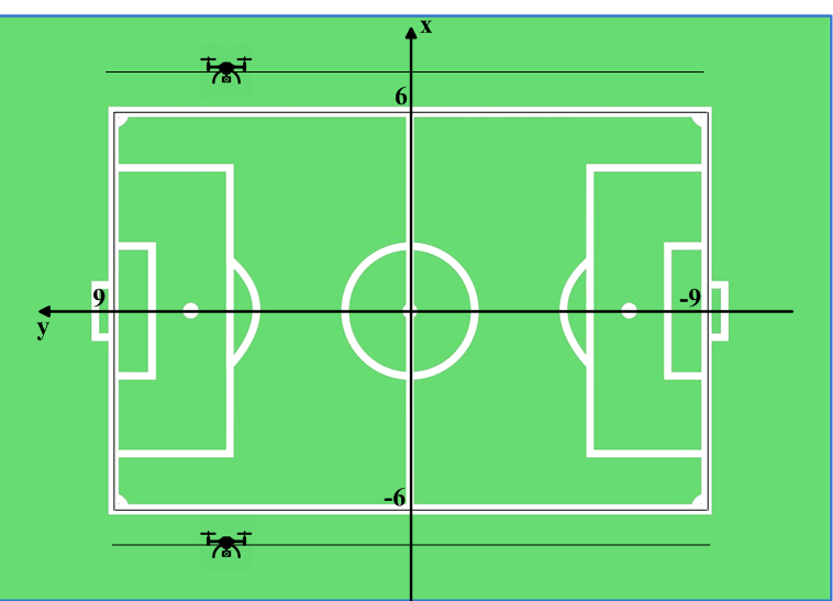
The dimension of the field is 18m x 12m, and the origin is at the centre of the field.
Algorithm
Since the drone moves on the lines parallel to the sidelines and the same altitude, the x and z-coordinate references of the drone ![]() and
and ![]() are fixed. In this way, only y-coordinate and yaw angle change.In our algorithm, we set
are fixed. In this way, only y-coordinate and yaw angle change.In our algorithm, we set ![]() (the value is -7 for the other drone) and
(the value is -7 for the other drone) and ![]() .
.
The following notations are made:
At sampling time k-1, the ball position is ![]() .
.
At sampling time k, the ball position is ![]() , and the drone position is
, and the drone position is ![]() .
.
Since the ball velocity does not change in two consecutive sampling periods, the predicted ball position at sampling time k+1 can be computed as


The path planning method is then described as follows:
We assume there is a circle, with a radius of ![]() , whose centre is
, whose centre is ![]() .
.
Then we decide whether we rotate or move (or both) based on the relationship between dist and ![]() :
:
1. If dist < R:
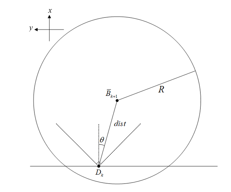
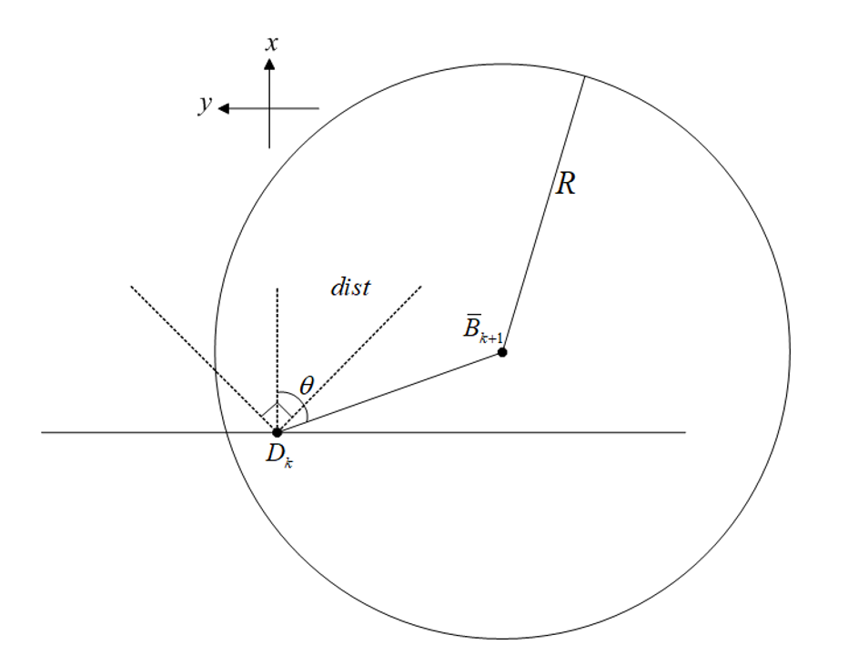
2. If dist > R:
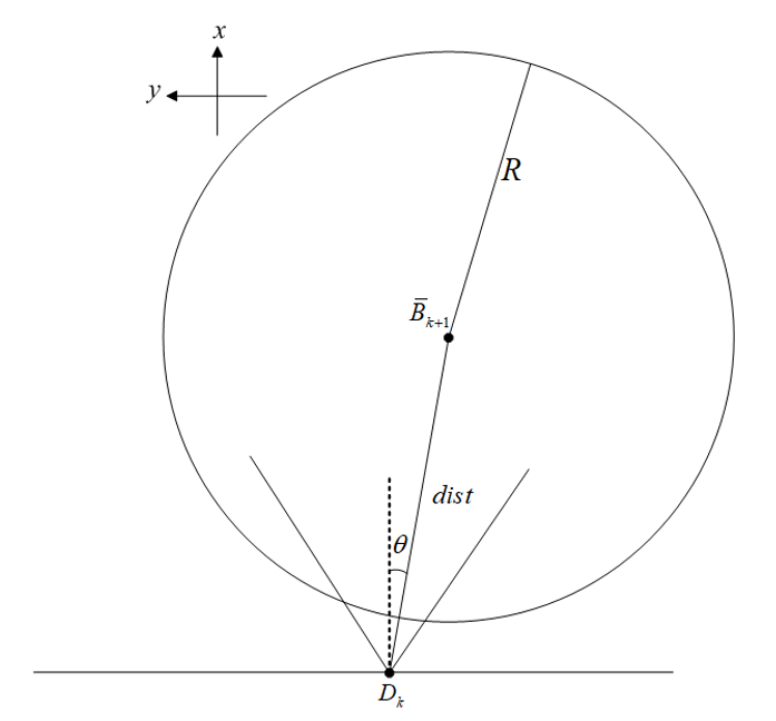
- Under this circumstance, the drone can track the y-coordinate of the ball. We can set the drone reference at the sampling time k+1 as
 .
.  is the maximum distance that the drone can travel per second. Since the sampling frequency in the Visualizer is between 16 Hz and 20 Hz, we set
  as the distance that a drone can go in a sampling period. In this scenario, the yaw reference changes as well
  .
.
The implementation of the algorithm can be found here and here.
Algorithm 2 -- Drone moving in a circle
The objective of this path planning algorithm is to find the shortest path for the drone while keeping the ball in the field of view. This is to minimise the mobility of the drone under given performance constraints to ensure a stable view from the onboard camera. This is done by keeping the ball's position as a reference and thereafter, using the ball velocity to predict the future ball position.
The reason to implement a second algorithm to capture the area of interest was mainly to test, apply and compare different strategies that work out best for every kind of game data. Drone in a circle is not only a good algorithm to capture the point of interest in a visualiser but also in a real game that uses a camera sensor to get the input data.
Assumptions
- The altitude,
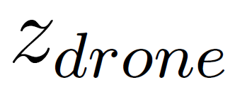 of the drone is same throughout the duration of the game.
 - The ball is always on the ground, i.e.,
 .
. - The drone encounters no obstacles at altitude,
 .
.
Algorithm
Let ![]() and
and ![]() be the radius of the circle around the ball, and the distance of the drone from the ball respectively. The drone holds its current position for
be the radius of the circle around the ball, and the distance of the drone from the ball respectively. The drone holds its current position for ![]() and tracks the ball as
and tracks the ball as ![]() exceeds
exceeds ![]() as shown in Fig below.
as shown in Fig below.
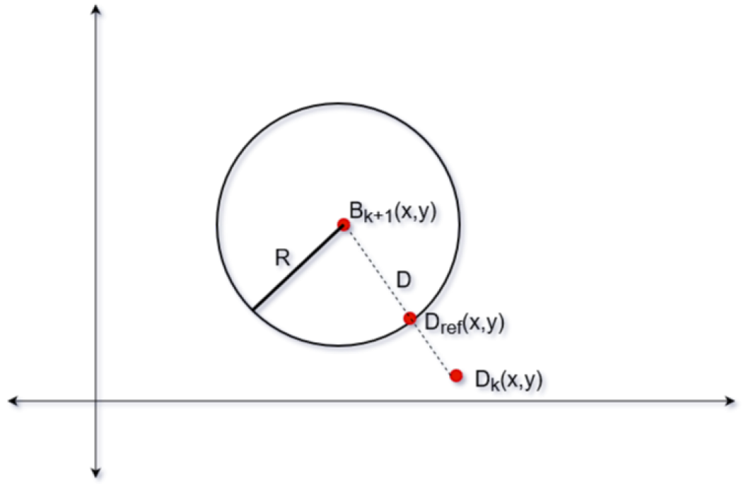
Let ![]() be the position of the ball at sampling time
be the position of the ball at sampling time ![]()
![]() be the sampling position of the ball at sampling time
be the sampling position of the ball at sampling time ![]() . The predicted position of the ball is therefore given by the following equation:
. The predicted position of the ball is therefore given by the following equation:


where ![]() is the time taken by the drone to travel from position
is the time taken by the drone to travel from position ![]() to
to ![]() . Distance,
. Distance, ![]() is then defined as follows:
is then defined as follows:
![]() are the reference coordinates for the drone to achieve within time period,
are the reference coordinates for the drone to achieve within time period, ![]() and is denoted by the following equation:
and is denoted by the following equation:
where ![]() is the maximum speed of the drone. The yaw reference for the drone,
is the maximum speed of the drone. The yaw reference for the drone, ![]() is given by the following equation:
is given by the following equation:

The ![]() are then fed to the drone to move around in a circle and capture the area of interest.
are then fed to the drone to move around in a circle and capture the area of interest.
NOTE: Since the visualizer has limitations to properly reproduce the yaw movement, the demonstration of the drone is a circle cannot be demonstrated and tested with the visualizer at this point. The implementation of this algorithm can be found here.
Transferring the coordinate in the Visualizer reference frame to that in the beacon reference frame
The dimension of the field in the Visualizer is ![]() , and the origin of the Visualizerframe is at the centre of the field. The dimension of the field at Tech United is
, and the origin of the Visualizerframe is at the centre of the field. The dimension of the field at Tech United is ![]() , and the origin of the beacon frame is at the centre of the beacon 0. Therefore, the planned path in the Visualizer cannot be applied in reality, unless we transfer the planned path in the Visualizer into that in the beacon frame. The transformation is depicted below.
, and the origin of the beacon frame is at the centre of the beacon 0. Therefore, the planned path in the Visualizer cannot be applied in reality, unless we transfer the planned path in the Visualizer into that in the beacon frame. The transformation is depicted below.
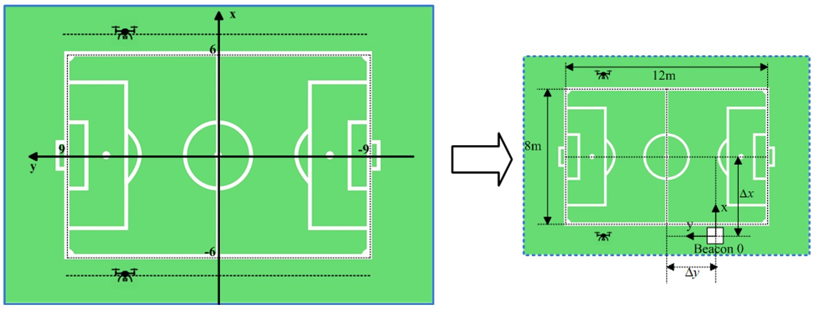
Since we only consider this problem in the 2D frame, we do not transfer the z-coordinate.
Assume that the coordinate in the Visualizer reference frame is ![]() , and the coordinate in the beacon reference frame is
, and the coordinate in the beacon reference frame is ![]() .
.
Visualization
There are two goals for implementing a Visualizer. One is to verify and validate the concept of the path planning algorithm during the development process, and the other is to demonstrate the result of our system. To realize the goals, the scenario of using the Visualizer will be to replay the previous game of Tech United in the Visualizer and programmatically control the view angle and position, which will represent the camera view from the camera mounted on the physical drone. There will be drones flying synchronously in the virtual world and physical world, both are taking the set-points from the path planner. Considering the compatibility with previous game data, we decided to adopt the existed Visualizer of Tech United and modify the source code to meet our requirements. There were two functions implemented in the Visualizer which are described below.
Previous Game Data Extraction
To extract the ball position from the previous game data and transfer it to the path planner, we tried to retrieve the ball position from the data file loaded when replaying the previous game. After a few attempts, it turns out that it would be more straightforward to save the ball position into a matrix when it is used in the original program. A function is built to implement this.
Drone Camera View Control
To show what the camera mounted on the drone is filming in the virtual world, we need to manipulate the position of the camera position and camera target position in the simulation environment. The camera position is assumed as the drone position, which can be directly retrieved from the path planner as coordinate x, y and z. The camera target position is calculated as below.
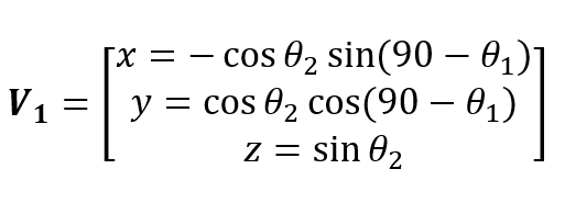
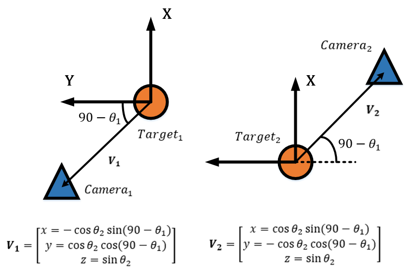
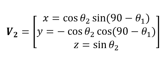
As we have two drones flying in the virtual world, due to the orientation of coordinate systems, the calculations of view target positions are slightly different from each other. However, the concepts are the same. We derive them as the equation below shown, as the vector V represents the normalized vector of vector indicating Target to Camera.
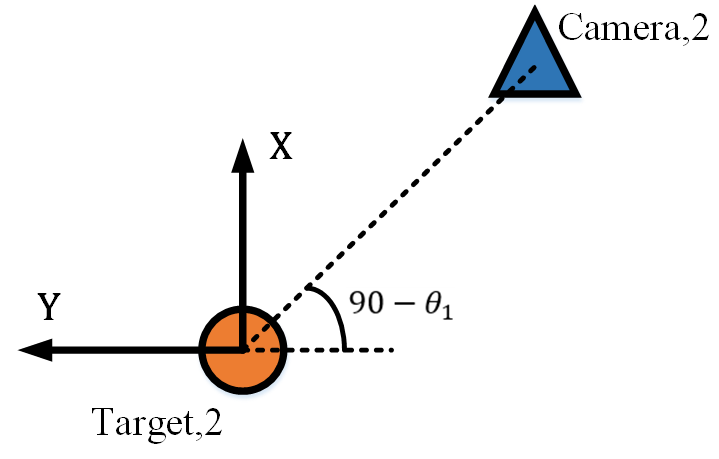
To calculate the V, the yaw angle of the drone θ1 will be used and the field angle of the camera θ2 has to be derived with the formula below, as the figure shows.
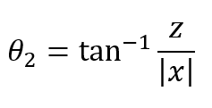

With θ1 indicating the angles as the figure shown, V will be calculated as the formula shown.
Vision System
The fundamental goal is to referee the game of football. While testing for this project is a two vs. two game between two robots at the Tech United field facilities, the ultimate vision is that the system could be scaled and adapted for use in a real outdoor game between human beings. From the experience of previous projects, the client imposed the direction that the developed system uses drones with cameras. The main benefit of this being the relative convenience of setting up and the assumption that this dynamic capability would save cost by allowing for fewer cameras for comparable camera coverage.
The work activity relating to the camera system was divided into two workstreams to allow for concurrent work activity. 1) The selection and integration of the hardware, such that it would not adversely affect the flight dynamics of the drone. Owing to the small size of the Crazyflie 2 drone, and the additional safety issues with using the larger drone variant with extra load capacity, we were restricted to using a small FPV camera because of latency issues with other options, as discussed here. While this option allows for a live camera feed to an external referee, this option seemingly does not allow for further processing of those images without significant delay. So this option would only ever allow for the most basic of systems, requiring humans firmly in the driving seat of all decision making. While this simplification was deemed an acceptable compromise for the scope of this project, it is assumed that the project will be continued by others, and so this is an essential factor to consider. In this project, we also assumed that the position of the ball and players is known, as this data has been taken from previous games that have been recorded from the server. In the real case, this would not be available, and mechanisms to determine this input must be a part of the system itself. 2) Intending to address both of those points, other workstream relating to the camera system focused on obtaining information from the data captured in the video streams, which is the software aspect. As the first step in that direction, the specific objective here was focused on getting the ball position so that this could input into algorithm 1 and algorithm 2 and also update the Visualizer views. At this stage, the player positions have not been considered, as this information is required for more granular decisions.
Hardware
The camera on the drone is the subsystem that fulfill the requirement to stream the gameplay from the drone point of view. Additionally, the image streamed by the camera on the drone is also expected to obtain information from the actual field (e.g ball/player location). During the projects, three design options are considered and analyzed, see Table below
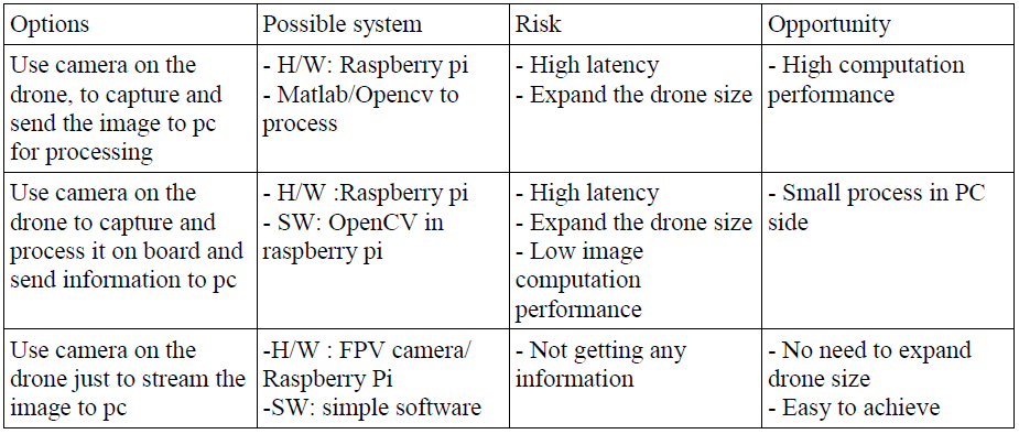
The first option is analyzed by investigating the communication performance between raspberry pi and pc. The communication uses IP communication. Some setting change is observed to verify the communication performance, such as changing from TCP protocol to UDP and use different wifi router. The result shows high latency with the fastest would be 0.6s. This shows that wireless communication is not reliable to give field information (e.g ball location), hence we leave this option out.
For the second option, it has a risk of processing burden in raspberry pi to handle communication and image processing. In addition, more work is required on the drone system (e.g the drone needs to be expanded).
Given the consideration above, the requirement for the vision system is concluded as to only streaming video (option 3). Therefore, an FPV camera is chosen as camera on crazyflie drone.
Final vision system setup:
- Wolfwhoop WT05FPV Camera
- Skydroid 5.7 dual receiver
Operation:
- Connect the power cable from FPV camera with crazyflie battery.
- Connect skydroid receiver to pc run any webcam software/choose as second webcam for opencv.
- Set radio frequency in FPV camera into skydroid receiver frequency .
Software
The initial step in developing this interpretation aspect of the camera system was to construct a scale model of the real field. Owing to logistical reasons, such as availability of the actual field and distance from our office, this proved to be a useful and convenient tool in early-stage prototyping of ideas. From this, we determined a first attempt strategy of a fixed camera, independent of the drone, to capture the ball and whole field. Then by taking the homography, we could determine the world co-ordinate of the ball with respect to the field from the image space. Several issues where identified from conducting scale model testing, such as bright spots, occlusions, and changes in lighting condition. In order to overcome these issues, the first step would be to apply a mask to the image; this would block out the background so that only the field area would be considered. At this early stage, occlusions would just be accepted, and in such cases, the system would not be able to provide a decisive location for the ball. This was deemed to be acceptable because the dynamics of the game mean that occlusions are usually temporary, and the drone would only move with a quite significant change in ball position anyway. From testing on the model and the actual field, it was found that occlusions are not as substantial as was expected. Of course, the use of extra cameras would also further reduce this impact. To address the issue of changing light conditions, using Hue, Saturation, Value (HSV) color rather than RGB color significantly reduced the effect of this. For this first proof of concept in the specific test environment, a bright orange ball was used, and so we could expect high contrast with all other actors on the field; also, the light conditions at the Tech United facilities are well controlled. To improve system quality, several filters are applied to the image, such as erosion and dilation, and the position of the ball in the image is identified by blob detection and taking the centroid.
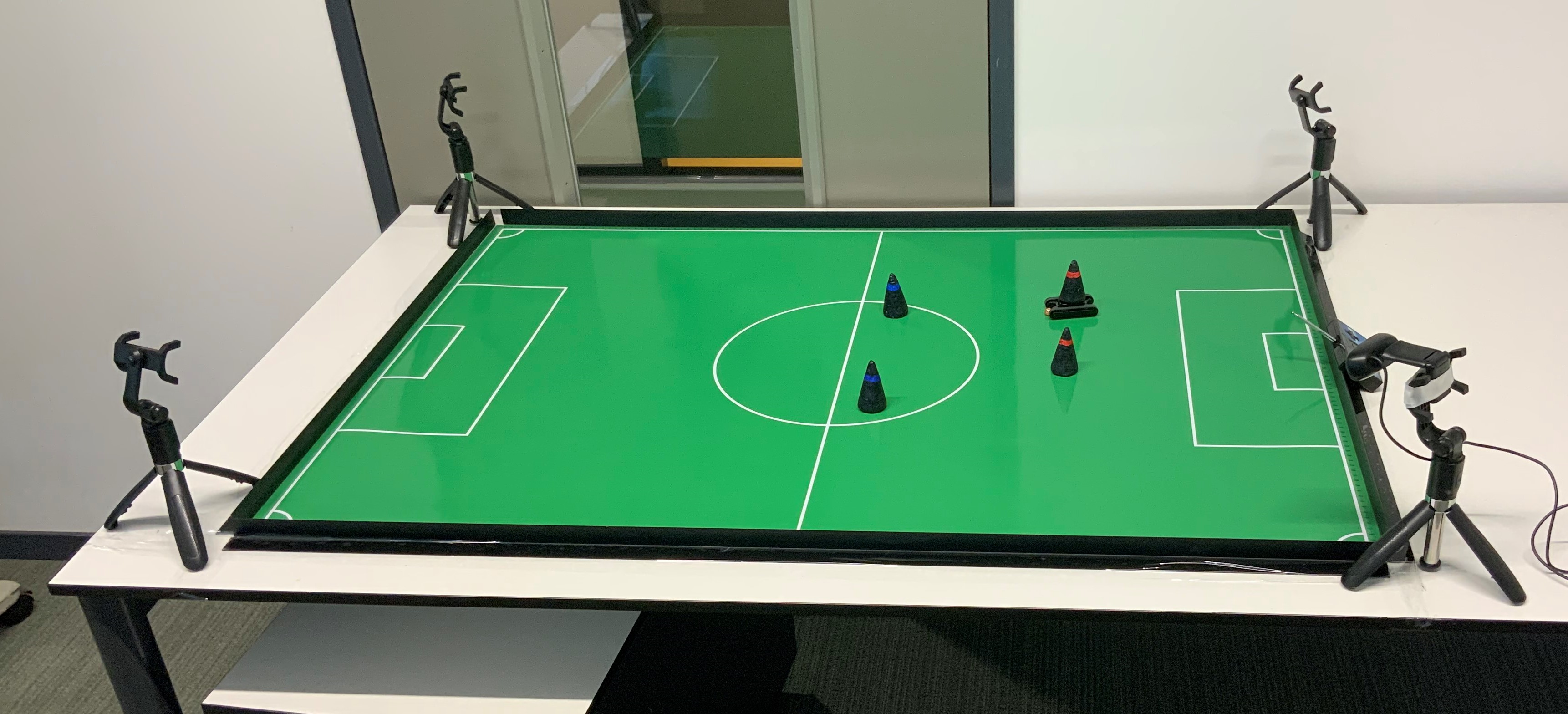
It was found that the most convenient option would be to use the camera built into a mobile phone. From a practical point of view, this also has the benefit that everyone tends to carry a cellular phone around with them. In order to do this, the Epoccam app was used that allows the mobile phone to be used as a wireless webcam. It was found that if both the phone and laptop where connected to the Eduroam network, then there was no discernable latency issue. This was also tested using a mobile data hotspot, and this also proved to have excellent performance. In order to mount the mobile phone, a camera mount was constructed from a selfy-stick and a 3d printed base that allowed it to be secured to a scaffolding pole at the field site. On the field, testing showed that the delay and accuracy were both completely reasonable. At the extreme corners of the field from the camera, the system placed the ball within less than one meter of precision on a first attempt; this was deemed adequate just for informing the drone position. At the center of the field, the precision was within 20cm. Due to the coronavirus, further testing and refinement were not possible. There is, however, the scope for plenty of improvement if it should be needed. The camera was only placed 2m off the ground, and so this means that, at that height, at the extremes of the field, the field line angles are very acute. Also, the image quality was only set to low during that particular test. The testing that was done at the higher resolution showed no noticeable drop in latency.
NOTE: It is assumed that the ball remains on the ground. From analyzing gameplay footage, it is apparent that for the vast majority of cases where the ball is not on the ground is when a robot shoots. The most straightforward approach to deal with this more complicated scenario is to be directly above the goal looking down so that you also only need to consider a 2D problem. In the simulator video that uses server data collected from the combination of all the robot players, it can be seen that they also often lose track of the ball in this scenario. These use much higher quality equipment, and there a multiple of them, so it does not seem likely that this is something the drone could do. So a view from directly above would most likely be the most robust approach. This has not been investigated further because of the coronavirus.
Integration
This task integrates all the subsystem according to three deliveries defined. Those deliveries are defined as follows:
First Delivery: Reading from Visualizer data, translate it as drone setpoints sequence
The goal for this delivery is to verify the path planning algorithm in Visualizer. The plan is to extract the ball location data of previous game data (e.g to .csv file) and translate that into drone setpoint which will be equal to point of view location in Visualizer.
The expected result would be the point of view in Visualizer that play a recorded gameplay is equal to the setpoint generated by path planning algorithm .The integration task for this delivery involves Visualizer, and path planning algorithm. In general, the task identified are to answer these questions:
- How path planning is implemented and get ball location from a recorded techunited’s gameplay.
- How the setpoints produced by Visualizer is read by Visualizer as point of view.
These questions are solved by logging the ball location simultaneously while a gameplay is played. The path planning algorithm read this csv file as a matrix of ball location and return another .csv file that contains a matrix of camera/drone location. The Visualizer then is modified to read .csv file with camera location and insert that as Visualizer's point of view.

Second Delivery: Implement the drone setpoint from previous gameplay on the crazyflie
The goal for this strategy is to verify the drone behavior based on setpoints given (e.g response time, maximum speed). Crazyflie read the .csv file of setpoint produced by previous delivery. This strategy shows the drone flies in the actual field based on the setpoint sequence generated, while the drone location is fed to Visualizer that playing a game data. The expected result would be the location of the camera in Visualizer is synchronized with the ground truth of drone location and hence the goals are achieved.

This strategy will be the first delivery of the project where the drone flies in the actual field based on the setpoint sequence generated, while the drone location is fed to Visualizer that playing a game data. The expected result would be the location of the camera in Visualizer is synchronized with the ground truth of drone location and hence the goals are achieved.This integration task involves drone, Visualizer, and path planning subsystem. The sub-tasks which are addressed should be:
- Transform frame reference from Visualizer and drone
Since both use different frame reference, transforming the coordinate is required between loco positioning system(lps) and Visualizer. We decided to add this functionality in drone system: drone transform the setpoint to its lps coordinate and transform its ground truth position to Visualizer coordinate which is fed to Visualizer as camera position.
- Communication between drone and Visualizer
The Visualizer is run in matlab enviroment while the drone is in python environment. To enable transferring the data from the drone to Visualizer, two options are considered:
- Drone write a file (e.g csv file) that contains drone actual location, and Visualizer read the file as Visualizer camera position
- Use socket communication, to communicate between the process
Both are feasible and tested with minimum code (<socket communication> <csv communication>). The second option has been tested with crazyflie running. Following are the pros and cons between the options:

The video below shows the result of integrating algorithm 1 with the visualizer.

The video below shows the result of integrating algorithm 2 with the visualizer.

Final delivery: Get ball location from vision system, translate it as drone setpoints sequence

Figure above shows how this strategy will look like. Based on the analysis for the camera on the drone, it is decided to use a static vision system to get the ball location. This static camera feeds ball location into path planning algorithm that later will generate the drone set point.
Since the ball localizing system can be developed in any system, integration between static vision system is considered based on different scenarios.

The video below shows the result of integrating vision system with the visualizer.
