Drone Referee - MSD 2018/9
Introduction
Football is a long-lived and well-liked sport which is a widespread passion nowadays. Consequently, it represents a growing industry with a huge market size. On the other hand, technological advancements are growing rapidly in different sections of humans’ lives, sports and more specifically football is not an exception. Some examples of the new technologies used are: automatic goal detection [1], use of trackers to monitor players' performance [2], soccer robots (the players are robots) [3], etc.
One possibility of technology usage in football matches is to use a drone referee instead of a human referee or a camera system covering the field. This system provides several advantages with respect to the mentioned conventional refereeing methods. First, human referees are naturally prone to human errors, which are one of the main sources of controversy in the game by possible unfair decision making. A camera-based autonomous system would remove the unfairness factor since every game would be refereed according to the same algorithm and would cover virtually any possible game situation, it is still rather very expensive in many situations such as regional games. A moving camera provided by the drone can therefore replace such an expensive system, and therefore appeal to a large market. While the technology to automatically enforce the rules of the game based on video is not available yet, a camera system capturing important game situations can assist a remote referee, by providing video and repetitions based on which, the he/she is able to provide some decision and send them to the ultimate referee.
The use of a remote referee also makes sense in a robot soccer match, where, although the players are robots, the referee is still human. In this case, in addition to the difficulties of a human players football match refereeing, there are some rules in particular which are difficult to be checked and enforced by a human referee but rather easy for an autonomous referee with a vision system.
In summary, the current football industry can be described by:
• Football is a growing industry with a market size of several billions of euros.
• Human referees, naturally are prone to human errors.
• Unfair situations will happen in a game; where, both financial and emotional stakes are high.
Solution
• Autonomous refereeing system
Scope
Design an autonomous referring system for Robocup middle size league (MSL) using drones.
Deliverables
1. System Architecture
2. Drone refereeing system
3. Wiki page documentation
Architecture
In this part we introduce CAFCR and its role in building our architecture (RAS & MSL)
Introduction and overview
CAFCR
Referee aiding system
Referee aiding system (RAS)
RAS CAFCR
RAS use case
RAS context diagrams
MSL/Ball-Following 2D
MSL/Ball-Following 2D CAFCR
MSL/Ball-Following 2D use cases
MSL/Ball-Following 2D context diagrams
MSL/Ball-Following 2D sub-systems
Drone
World model
Functions:
- Acts as system’s model, avoiding lateral dependencies between sub-systems,
- State storage for the whole system,
- Master message-passing node for sub-systems,
- Single logging point of the system.
Camera footage system and HMI
Supervisor
Introduction
The supervisor is a subsystem of RAS. This subsystem is responsible for providing high level control states for the other subsystems of RAS. Furthermore, it is responsible for translating user commands to states. The supervisor subsystem monitors the overall safety of RAS.
Architecture constraints
RAS
The supervisor subsystem is responsible for keeping record of the states of RAS.
The supervisor must capture the game, before game, emergency situation in its states.
The states of the supervisor must be accessible to other subsystems of RAS.
Drone MSL
Supervisor states must include drone positioning as additional states.
Supervisor must include drone emergency situations in its states.
Supervisor states are independent on MSL sub-packages (2d, gimbal, inclined?)
Supervisor takes input from MSL referee box through json interface.
Supervisor takes land, take off, safe to land from remote referee through world model
Supervisor gives the high level game states as outputs through world model
Supervisor enabled the RR to land from any point in the field.
Supervisor enables the drone to take off after takeoff command receive from RR.
Supervisor enable the drone to start refereeing the game after receiving the start game signal form MSL referee box.
Supervisor dictates that after a half time ends drone will hover above landing position.
Supervisor dictates that after receiving the land command drone will hover above landing position.
Supervisor enables the landing of the drone after checking it safe to land from both RR and drone action planner. State transition: check with AP requirements.
System description
In this section, a description of the supervisor subsystem for the MSL 2D architectural package will be shown. The description is divided into four points. These points are scenarios, purpose, inputs and outputs.
Scenarios
In the upcoming sub-section, selected game operation scenarios are presented. The purpose of these scenarios is to show the sequence of events of running game. These sequences are the result of application of the requirements or constraints to our drone referee system. In the next part, we will try to use these scenarios to obtain supervisory states for our MSL 2D architectural package. These scenarios are game, intentional landing and emergencies scenarios.
Game scenario
This scenario shows a complete sequence for the first half time of a MSL 2D game. The step sequence is the following:
1. RR makes sure robot players are positioned in center.
2. RR press take off using HMI.
3. Drone takes off then flies to start position. For MSL 2D ,the start position is the center of the pitch.
4. Drone is hovering at start position.
5. MSL referee issues start game signal.
6. Game starts.
7. Drone starts the refereeing technique.
8. First half time is over.
9. MSL referee issues the end of the 1st half time signal.
10. Drones hovers above landing position.
11. RR presses it is okay to land in HMI.
12. Drone lands in the landing position.
13. Drone is waiting for another game start.
Intentional land scenarios
These scenarios represent situations where the RR wants to land the drone before and during game. In this document, two scenarios are shown. The first scenario (ILS1) ,where; the RR wants the drone to land before game start. While, the second one (ILS2), where, RR wants the drone to land during the game. The sequence of steps of ILS1 is:
1. RR makes sure robot players are positioned in center.
2. RR press take off using HMI.
3. Drone takes off then flies to start position. For MSL 2D ,the start position is the center of the pitch.
4. Drone is hovering at start position.
5. RR presses land in HMI.
6. Drones hovers above landing position.
7. RR presses it is okay to land in HMI.
8. Drone lands in the landing position.
9. Drone is waiting for another game start.
While, the steps for ILS2 are:
1. RR makes sure robot players are positioned in center.
2. RR press take off using HMI.
3. Drone takes off then flies to start position. For MSL 2D ,the start position is the center of the pitch.
4. Drone is hovering at start position.
5. MSL referee issues start game signal.
6. Game starts.
7. Drone starts the refereeing technique.
8. RR presses land in HMI.
9. Drones hovers above landing position.
10. RR presses it is okay to land in HMI.
11. Drone lands in the landing position.
12. Drone is waiting for another game start.
Drone Emergencies scenarios
In these scenarios, three sets of sequences are presented. These sequences deal with only one kind of emergency. This emergency is related to battery emergency at different moments the game. These moments are before game start and drone is still in land (EMS1), drone is hovering at center before game start (EMS2) and during game (EMS3). The sequence of steps of EMS1 is:
1. Before game, drone is on land
2. Drone emergency occurs
3. Drone is not able to takeoff despite any command given by RR
4. Drone will only be able to take off again only when emergency is solved
For EMS2, the sequence is :
1. RR makes sure robot players are positioned in center.
2. RR press take off using HMI.
3. Drone takes off then flies to start position. For MSL 2D ,the start position is the center of the pitch.
4. Drone is hovering at start position.
5. Drone emergency occurs
6. Drone lands
7. Drone is not able to takeoff despite any command given by RR
And for EMS3, the sequence is:
1. RR makes sure robot players are positioned in center.
2. RR press take off using HMI.
3. Drone takes off then flies to start position. For MSL 2D ,the start position is the center of the pitch.
4. Drone is hovering at start position.
5. MSL referee issues start game signal.
6. Game starts.
7. Drone starts the refereeing technique.
8. Drone emergency occurs
9. Drone lands
10. Drone is not able to takeoff despite any command given by RR
11. Drone will only be able to take off again only when emergency is solved
Functions
From the previous scenarios and constraints, the functions of the sub-system supervisor can be presented by these points:
• To take the remote referee’s commands, referee box game states and drone emergency as inputs
• To provide high level control ( game) states according to inputs.
• To provide reaction to emergency situations
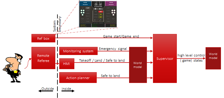
The other sub-systems will take action based on the high level abstract states. In figure , a context diagram for the supervisor subsystem is depicted. In this diagram, the inputs and outputs of the system are shown. Furthermore, the possible messages for each input or output are shown. In the figure, the system boundary line separates the subsystems of the drone referee form the outside environment.
Figure 1 Context diagram for the supervisor subsystem.
Inputs
Remote referee
The supervisor takes the takeoff, land and safe to land commands from the remote referee via HMI through world model.
Monitoring system
The supervisor reads the emergency status in the world model. This status is written by the monitoring system. Referee box
The supervisor reads the game status from the MSL HMI (ref box). Based on this status , supervisor can know when game starts and ends. Action planner
Action planner sends a “safe to and signal” to world model. The supervisor reads that signal from world model. Drone can only land when the two safety checks are fulfilled.
Output
High level control (game) states
Supervisor write these states into world model. Other subsystems like action planner read these states and take action based on them.
Design choices
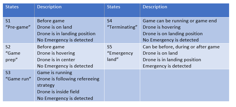
For the MSL 2D, the supervisor will have 5 states. The transition between these states are governed by transition conditions. These conditions are based on the values and combinations of the so called transition variables and the transition variables are based on the inputs of the supervisor subsystem. States
The 5 states of the supervisor are presented in table 1. Furthermore, table 1 shows the description of each state.
Table 1 State description
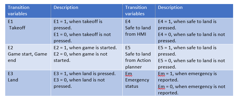
Transition variables
In table 2, the description, value, condition of each transition variable are shown.
Table 2 Transition variable description
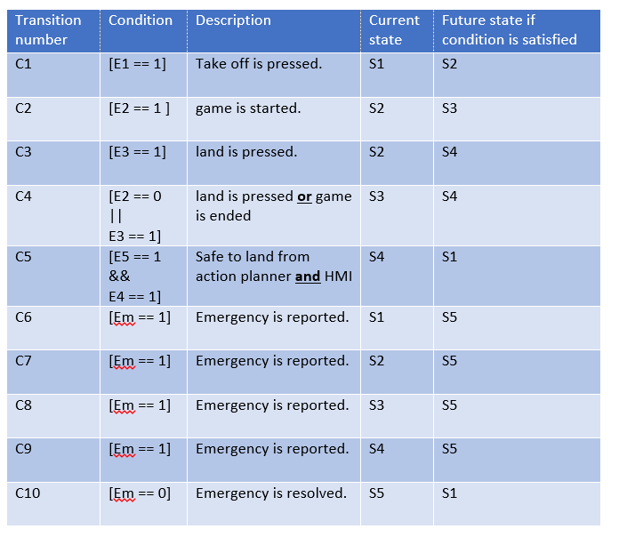
Transition conditions
They are conditions consisting of the variables and mathematical operators. The operators are || (OR) , == (EQUALS) and && (AND). Whenever, the condition is true, the supervisor is allowed to move from the current state to the future one. Tables 3 shows the description of each condition, the current state and the future sate.
Table 3 Transition conditions
State machine
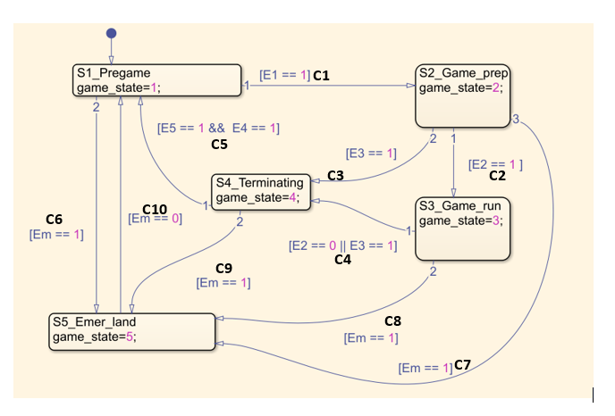
The complete state machine of the supervisor subsystem is shown in figure 2. The initial state of the system is S1. In the figure, the states, variables and conditions are shown. Furthermore, the output (high level control (game) states) of the supervisor is presented in the variable game_state. This variable is sent to world model and can be read by other subsystems.
Figure 2 State machine of the supervisor subsystem
Reaction to emergency situations
In MSL 2D, there are two emergency situations. The first one is drone emergency. While, the second one is dependent on the remote referee’s estimation. For both of these situations, the drone will land.
Assumptions
• RR must make sure that robots are in starting place while drone is hovering above starting position.
• RR must make sure that is safe to takeoff before pressing safe to take off in HMI.
• The drone emergency situations considered in the systems are only battery emergencies.
• RR must make sure there are no obstacles in the airfield and landing position.
• RR must make sure the safety net is closed.
• During game pauses drone will still follow the refereeing strategy.
• System’s initial state is always at S1
Technology
For this supervisor, Matlab Stateflow was used [add ref].
Recommendations
Emergency situations
Supervisor should consider other drone emergency situations. These situations can be obtained after experimentation of the system in several test runs. Furthermore, additional functional safety measures could be considered for each subsystem.
Model based supervisor
It was not possible for our team to model each subsystem separately and make maximal permissive supervisor with the time resources we had. Furthermore, the drone manufacturer used Matlab Simulink to control the drone. Designing a maximally permissive supervisor on Matlab is very difficult. Our recommendation is to model the subsystems using other supervisory control tools. After finishing the supervisor start couple it with Matlab. The challenge in this case would be modeling, capturing requirements and supervisor synthesis. [ add ref]
Simulation
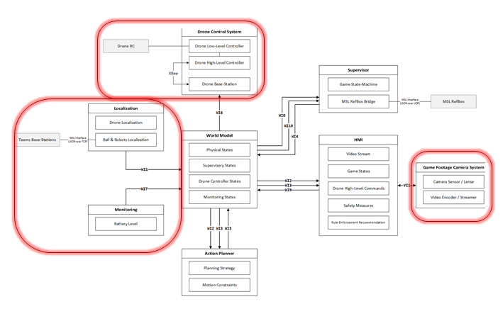
The software simulation has been implemnted to test and simulate the system. In the simulation, the hardware parts has been simulated. These parts have been highlighted in the context diagram below.
Drone
Simulated by use of dynamic equations of motion Instead of receiving feedback from sensors, it is received from the dynamic equations directly. Instead of sending PWM (pulse width modulation) to the brushless motor drivers, it is sent to the dynamic equations.
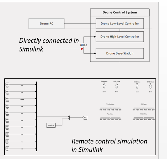
Remote control
Simulation is simulated in Simulink. Instead of sending data over X-bee, signals are directly connected in Simulink.
Features
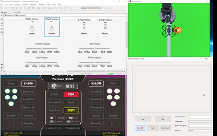
Simulated remote control
MSL referee box
Simulated view port of the camera
Remote referee HMI with out live camera feed
Simulation video
For the video, press this link [1]
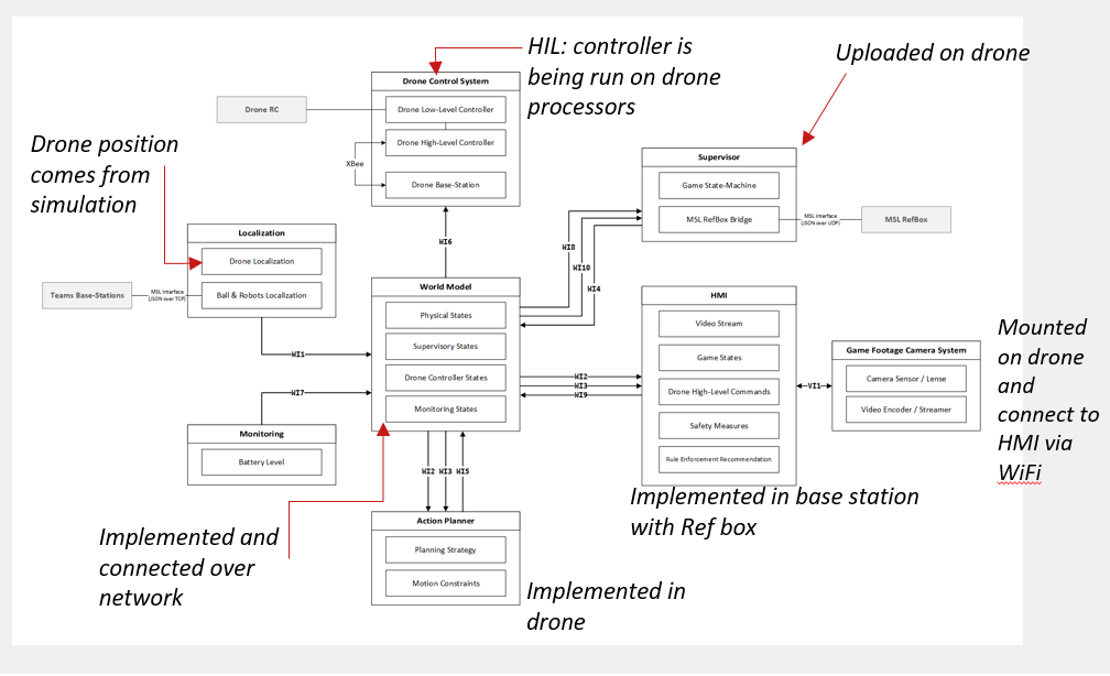
Full system integration with hardware in loop drone (HIL)
Purpose
Test all subsystems except for the drone, while MSL game is running.
Provide a proof of concept of the whole refereeing system
Act as mitigation action if Avualr hardware fails.
Test conditions
Test record
For the video, press this link [2]
MSL/Ball-Following Gimbal
MSL/Ball-Following Gimbal CAFCR
MSL/Ball-Following Gimbal use case
MSL/Ball-Following Gimbal context diagrams
Project Management
Introduction
Project management plan
Integration plan
Levels
Level 0 before world model integration (highest priority) Level 1 (two system elements together), 6 possible integrations Level 2 (three system elements together), 4 possible integrations Level 3 (Four system elements together), 1 possible integration Level 4 (Five system elements together), 1 possible integration
Level 0 before world model integration (highest priority)
HMI + Camera = HMI with camera (chosen by team) Action planner + drone = Linked action planner (should be implemented by Avular) Ball & Robot from Tech-united + drone from Avular = Position system (ball & robot & drone)
Level 1 (two system elements together), 6 possible integrations
Supervisor + HMI with camera Supervisor + Position system (ball & robot & drone) Supervisor + Linked action planner Position system (ball & robot & drone)+ HMI with camera Position system (ball & robot & drone)+ Linked action planner Linked action planner + HMI with camera
Level 2 (three system elements together), 4 possible integrations
Supervisor + HMI with camera + Linked action planner Supervisor + HMI with camera + Position system (ball & robot & drone) Supervisor + Linked action planner + Position system (ball & robot & drone) Linked action planner + HMI with camera + Position system(ball & robot & drone)
Level 3 (Four system elements together), 1 possible integration
Supervisor + HMI with camera + Linked action planner + Position system (ball & robot & drone)
Level 4 (Five system elements together), 1 possible integration
Supervisor + HMI with camera + Linked action planner + Position system (ball & robot & drone)+World Model GOAL!
Communication management plan
Quality management plan
Test management plan
Risk analysis
Implementation
Drone
Introduction
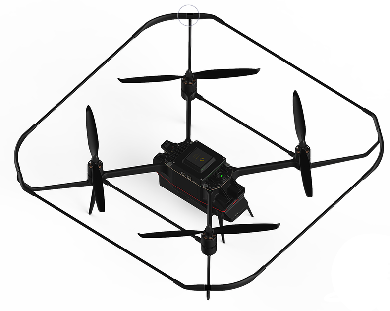
The drone is the main hardware subsystem of the RAS. This subsystem includes sensors, microcontroller, communication ports and mechanical components. The drone used in this project, is the last version of Avular curiosity drone provided by Avular company. The drone can be programmed by means of Matlab Simulink. All the other subsystems must eventually be implemented on the drone to achieve the final goal of refereeing the game.
Architecture constraints
- RAS:
The drone must be able to fly autonomously.
The drone is responsible to follow the command of action planner through world model
The sensors data must be accessible to world model (the other subsystem of RAS)
The drone should provide the battery level information to other subsystems.
The drone must have the possibility of installing the footage camera on it.
- Drone MSL:
The drone must be able to fly for 5+2 minutes and show the battery level all the time.
System description
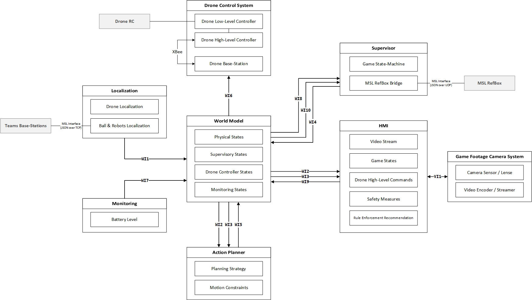
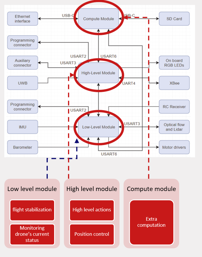
The drone is the main hardware subsystem of drone referee system which consists of different components and subsystems itself. The main task of the drone is to receive commands in real time from a remote computing module (usually a PC) and follow the action required from action planner while carrying the footage camera. For this need,the main challenge is programming the drone and setting the wireless connection for sending wireless data to the micro-controller present on the drone. The Avular curiosity drone can be programmed through three computing modules: Low-Level module, high-Level module and compute module. Each of these modules is responsible for part of the functionality of the drone, and is connected to a different set of sensors, actuators or communication devices. These modules, their general functionality and their communications are shown the the figure below. Each one of the High-Level and Low-Level Modules uses a 180MHz Cortex-M4 processor and the Compute Module is a Raspberry-Pi Compute Module 3.
The idea is to use Low-Level module for calculations related to flight stabilization and monitoring the current status of the drone, and use the High-Level Module for other high-level calculations, such as: path planning or position control of the drone which can be different depending on the project requirements. The Compute Module can be used in combination with both High-Level and Low-Level Modules for intensive computations. In drone referee project it is only used for comunication with the footage camera as mentioned before in the camera section.
Functionality Overview
After programming the Low-Level and High-Level modules, communication to the drone is possible through X-bee and by means of MAVLink protocol. An overview of this communication process is shown in figure below.
Technology
In this project only High-Level and Low-Level modules are used for programming the drone. They are programmed in MATLAB-Simulink via ST-link programmer.
Subsystem Results
In this section all the tests done by the drone and their results will be shown.
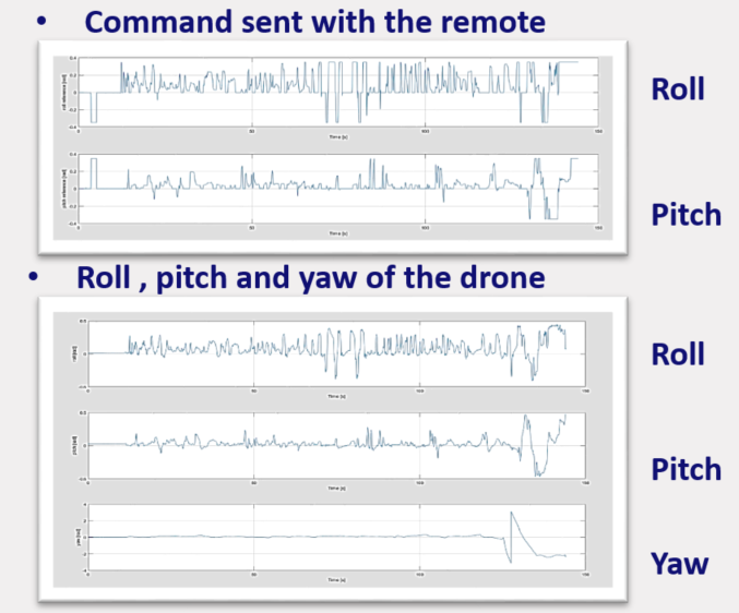
Flying manually with the remote control
Diagnosed Problems
- Hardware: defective battery
- Software: Probably Kalman filter/Low level control
Solutions
- New batteries (at least 3)
- More tests to improve the low control system
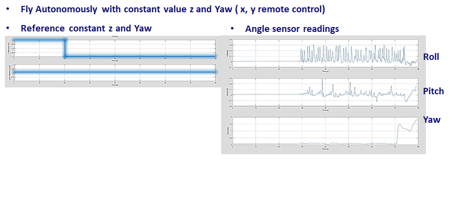
Autonomous flight
Diagnosed Problems
Incorrect sensor reading (Probably the magnetometer)
Solutions
- Better calibration sensors
- Use other measurement techniques
Localization system, UWB (Ultra-wide band) flight
Diagnosed Problems
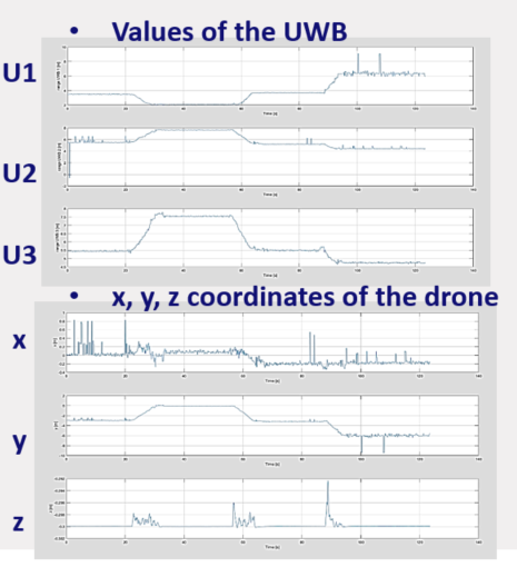
Noisy Ultra-wide band data
Solutions
- Better calibration of the UWB
- Apply a median-filter in the MATLAB algorithm
Autonomous flight II
In this test, drone is controlled autonomously in Z direction and manually in x,y and yaw. Controlling Z position of the drone was successfully performed. This test is shown in the video below:
??
Recommendations
World model
- Binary serialization of data for each interface,
- Uses UDP for sending/receiving information for each interface,
- Implemented in Simulink,
- Simulink and C# clients are implemented.
Camera footage system and HMI
Introduction
The purpose of camera footage system and the HMI is to provide video stream on game referee’s console. Camera attached to the drone should provide enough situational awareness to enable referee to take decisions. Additionally, referee should be provided with recommendations such as ball out of pitch, collision between players to help him make better decisions.
Requirements and architecture constraints
After discussion with stakeholders and team members following requirement and constraints were imposed on the system
1. Referee’s HMI shall display raw video from received video stream
The HMI should show the video stream of the game on referee’s console.
2. The “Game Footage Camera’s ” parameters (FOV, depth-of field etc.) shall be chosen to cover 4-5 meters of field of view (FOV) around the ball, with nominal allowable flight height in each match
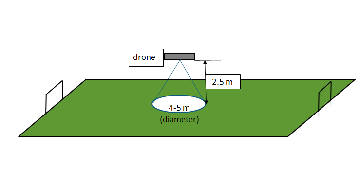
It is important for referee to see enough area around the ball to make proper judgement. After discussion with the experienced robosoccer referee, it was decided that it is preferable to have 4-5 meters of field of view around the ball. The field of view is dependent on the height at which drone of the flying.
3. The overall streaming delay (from real-scene viewed by camera to the video stream displayed for the RR ) shall be less than 0.5 sec
In sports it’s important for referee to make decisions as soon as possible. Therefore, the referee should be able to see the video with as less delay as possible. Based on the feedback received from the experienced referee the delay should not be more than 0.5 seconds.
4. Any image processing (detection/distortion improvements/ marking boundaries etc.) shall be done on external processors
To have minimum footprints in terms of size, processing power and energy consumption all the image processing should be done on an external processor.
5. Each video stream shall take less than 10% of the network link bandwidth
System needs to be scalable for multiple cameras, referee consoles. Therefore each video stream should not consume more than 10% of the network bandwidth.
6. Any on-board camera on any drone shall stream raw video to referee’s HMI using network connection
Camera should use network connection for streaming in order to make the system flexible and scalable.
7. RR laptops and any drones within DR system shall be accessible for each other over a wireless network connection
System description
The figure below shows the camera and referee HMI system
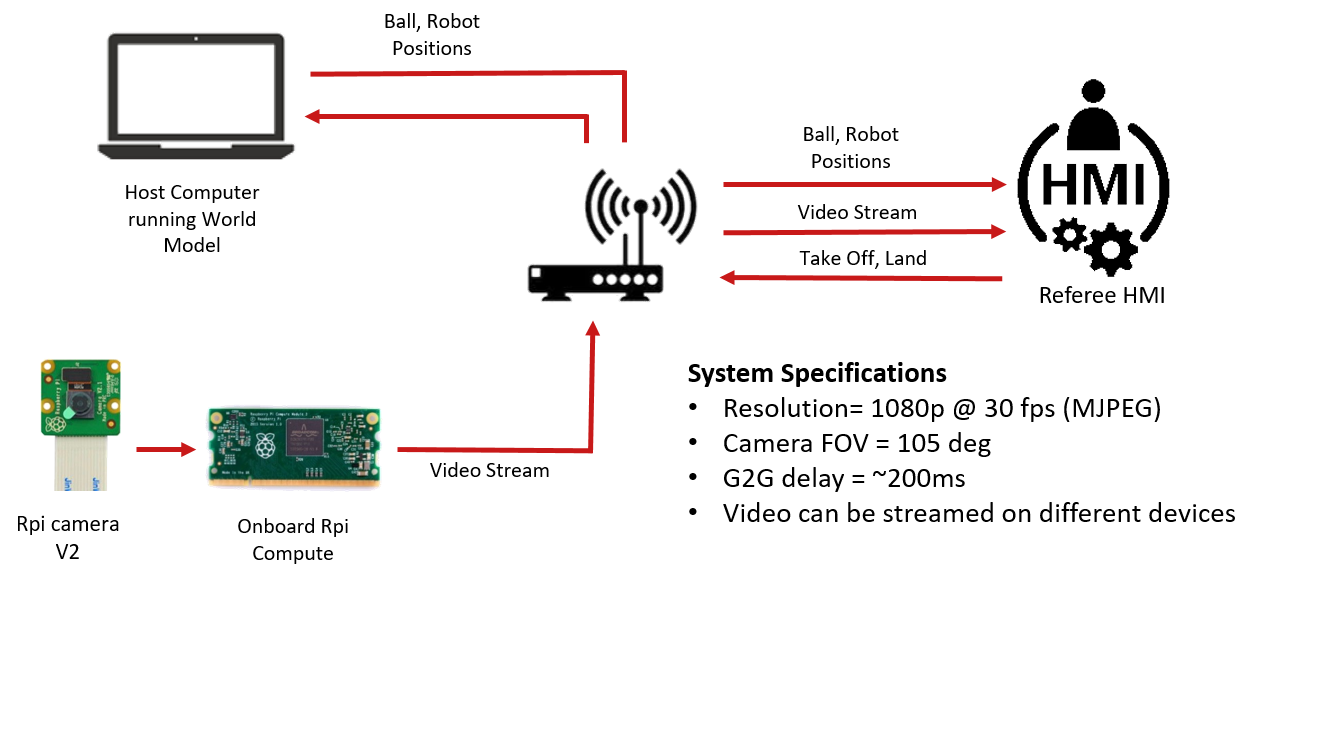
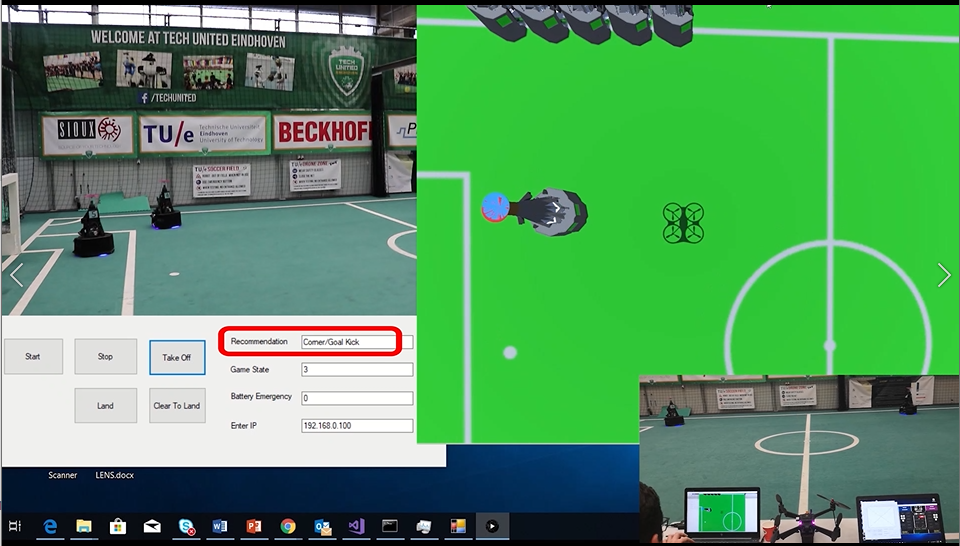
System consists of camera sensor connected to raspberry pi streaming the video on HMI. The camera is mechanically mounted on the drone with the lens looking vertically downwards. The HMI is programmed in C# which makes it portable to different devices running Windows operating system. HMI also communicates with the world model running on host computer to receive ball, robot and drone position streams. This information can be used for giving useful recommendation to the referee. Current HMI can recommend referee to award corner, throw in or goal kick when ball goes out of the pitch. Referee can also send commands to take off or land the drone from the HMI. Game states described in section 4.4, are also displayed on the HMI.
Subsystems
Raspberry Pi with camera and Lenses
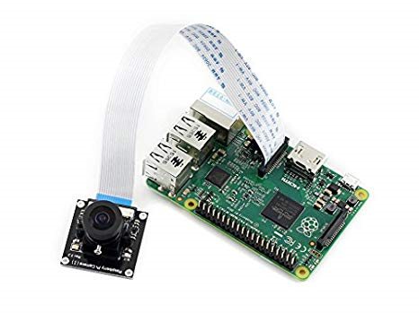
Raspberry pi camera module was chosen because of the following reasons
• Modularity: Pi camera can be attached with different lenses which offer different field of views
• Flexibility: Raspberry pi can be configured to work with different video codecs which can be adapted to different hardware
• Community Support: Raspberry Pi has large user community support
• Availability: Avular drone has raspberry compute module onboard which supports the camera and eliminates requirement of additional hardware
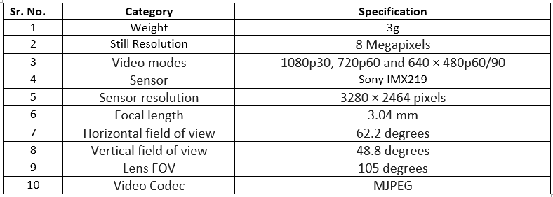
Below are the specifications of the camera and lens
Human Machine Interface(HMI)=
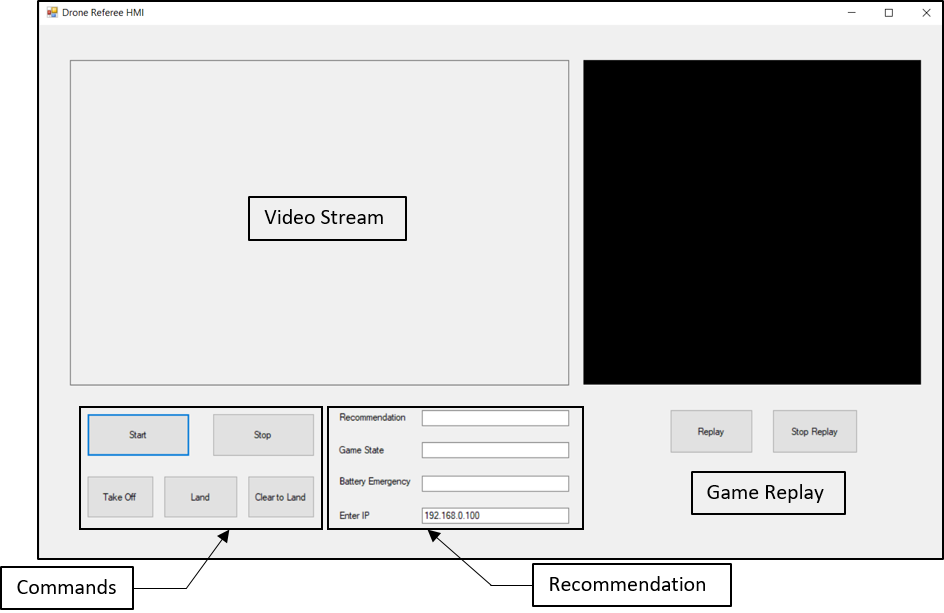
Fig. above shows Human Machine Interface(HMI) for the drone referee. The HMI is programmed in C# which communicates with world model running in MATLAB over the network. The application can be ported to different devices running windows. HMI has following functions
• To display video stream from camera
• Provide replay of last 30 seconds as and when needed
• Send take off, clear to land and land commands to drone
• Display recommendations such as goal kick, corner and throw in
• Display state of the game
Interfaces
Remote Referee
The supervisor receives Take Off, Clear to Land and Land commands from remote referee.
World Model
The HMI receives Game States and Physical States(Extracted from positioning data) from the world model.
Technology
HMI is programmed using C# to make it portable and avoid dependency on MATLAB.
Supervisor
Action planner
Localization systems
Function
Provides the ball, individual robots and drones positions to the world model.
Ball localization system
Requirements and architecture constrains
Positioning System shall be able to:
1. Get ball’s position from any two teams playing in the field, when deployed for Robocup Middle Size league
2. Work with MSL’s standard data interface for monitoring game states (physical/non-physical), when deployed for Robocup Middle Size league.
3. Get position of any type/number of drone’s being used by the DR System.
4. Positioning System specification/implementation shall not be dependent on TechUnited or any other teams Design Choices, when deployed for Robocup Middle Size league.
System description
In a robot soccer team each of the turtles(soccer robots) and their DevPC of the team share data using a RTDB. The turtles share set of data that contains the robot id, robot position, ball position, ball velocity and the ball confidence. The DevPC hosts this RTDB server. According to the MSL rules each participating team are required to log these data on to the referee base station.
Overview
Figure 8, Block diagram of the positioning system
As shown in figure 8 there is an executable that reads data from the RTDB and converts into JSON(Java Script Object Notation) strings. This data is then transmitted over a TCP(Transfer Control Protocol) connection. The DevPC hosts the TCP server and the base stations acts as the TCP client and receives this data.
This system keeps receiving the JSON data until the connection is manually interrupted or a transmission error is encountered. The positioning system then receives the JSON data and parses them.
Figure 9 Integrated positioning system with world model
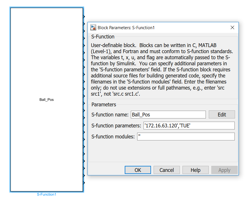
The Simulink block takes in the IP address of the TCP server and the team name as a parameter as shown in figure 3 and outputs the ball position with the highest confidence. In case of equal confidence the value with lower ID value is considered. The block also outputs position of the individual robots.
Drone localization system
Requirements and architecture constrains
???????????????????????????????????????????
Drone localization system overview
Figure 10, Overview of the drone localization system
Technology
The system was implemented using Avular ultra wide band system
Conclusions
As
Recommendations
The biggest challenge of the project was to make the hardware part concerning the drone and the sensors reliable and functional.
We have expected that to happen. We have included it into our risk mitigation plan. However, we believe that these problems will recur in the future due to the nature of the project.
Our recommendations are:
1. Extend the duration of the project (minimum 12 weeks)
2. Create a week of interaction between MSD groups over the years so that we can work on the same project clearly.
