PRE2018 3 Group13
Abstract
A robot which is able to read a book/form of text and is able to translate it into braille so that deaf-blind people can read it.
Problem statement
In this world, there is an estimate of around 356.000 deafblind people internationally. Only around 1% of all books are translated in braille which means that people who are deaf-blind have small amount of available reading material. Even the blind people will most often need to resort to audio books if they want to read a certain novel.
Objective
Make it possible for people whose only choice to read books is using braille to read books which are not translated in braille and give a choice to blind people who prefer to read in silence to do so.
Who are the users?
The users of our device will be people with visual and/or hearing impairments who know how to read braille. For the people with both visual and hearing impairments, they will use this product in order to read novels. For the people with just visual impairments, they will use the product incase they prefer to read in silence. Most visual impaired people have to resort to use audio books because of limited availability braille books.
What do they require?
A way to convert (digital) text to braille.
Solution:
Create a robot which is able to translate e-books into braille so that the users can read it. (with translate do not mean to write a new book with the translation but instead some other form of reusable interface.
Braille interface
Input
e-book / digital text
Output
physical braille letters
Prototype
Manual digital letter input for testing first, outputs a single braille letter. Multiple letter output can be considered afterwards.
Approach
If we build a prototype of the mechanical part: Firstly, we will research braille on which we can base our user requirements on. We then look for existing patents and their mechanics on a Braille output system and look for possible trade-offs. Once we have detailed insight on the possible solutions, we devise our own solution based on our design decisions that correspond to the user requirements. We make a concept to visualize our idea and eventually we will make a (physical) prototype that can be tested with our target users.
If we only focus on user-friendliness
Firstly, we will research braille on which we can base our user requirements on. We then look for the most user-friendly materials and user-interface so we can improve the user-friendliness of the machine.
Milestones
Have digital text be the input of a reusable interface where the text is converted to braille. The braille can be projected per word or group of words, depending on their length. Choose the research topic Summarize a State-of-the-Art by performing a literature study Find a contact person that fits our target user group to gather additional information regarding our case Create user requirements for the robot Validate the requirements with the contact person Design a concept build corresponding to the requirements Validate the concept with the contact person Build a prototype of our concept and test it with the contact person Produce a final presentation in which we discuss the process, design and prototype
Deliverables
Compact, user-friendly and cost-efficient physical braille interface. The Braille interface should accept digital text and convert it to several Braille characters at a time. User-friendliness consists of: Type of material to interact with Speed of the machine Possible physical interaction with buttons/triggers (functionality)
Possibly a working prototype of one or several letters, that can be reset and configures itself to a given input.
Who will do what
- Material choice
- Dennis
- User interface (layout, buttons etc.)
- Thomas
- Converting feedback of test person to useful information
- Luc
- Hardware internals stuff
- Luc
- Builder
- Simon
- Programmer if we build a 6-segment letter prototype
- Dirk
Planning
Planning
Week 2 (16 Dec - 22 Dec):
|
Task |
Person responsible |
Deadline |
Remarks |
Done |
|
Creating planning |
Everyone |
14-02-2019 |
||
|
Researching different materials: Making a overview of different materials based on multiple aspects such as cost, smoothness, stretchability or other factors which could be important. |
Dennis |
20-02-2019 |
Needs to add the references and finish small parts. Will be done before the tutor meeting |
|
|
Getting blind contacts, make appointment and creating a survey. |
Luc |
20-02-2019 |
Appointment date doesn’t have to be within the deadline |
Didn’t create survey |
|
Working out existing Braille mechanism solutions for six-dot cells and argue their (cost)effectiveness |
Thomas |
20-02-2019 |
Piezo-electro |
|
|
Creating system/process of taking .pdf text input and outputting Braille |
Dirk |
20-02-2019 |
Requires documentation First output to plain text and then to Braille |
|
|
Look for possibilities of creating Windows program that outputs to Arduino |
Simon |
20-02-2019 |
Requires documentation on choices made |
|
|
Discuss the survey contents |
Everyone |
20-02-2019 |
Content finished during meeting |
|
|
Put the planning in the wiki |
Simon |
20-02-2019 |
Week 3 (23 Dec - 29 Dec):
|
Task |
Person responsible |
Deadline |
Remarks |
done |
|
Word context to Braille shortcuts recognition |
Dirk |
27-02-2019 |
Optimization of .pdf to Braille system |
Optional function |
|
Finish survey layout and give it to our target group. |
Luc |
27-02-2019 |
Or interview them depending on the appointment |
No response from contacts |
|
Define the user requirements based on the results of the survey. |
Everyone |
27-02-2019 |
First iteration of the user requirements |
|
|
Defining the Braille mechanism |
Luc |
27-02-2019 |
Blueprint of how it should be constructed |
Needs some changes |
|
Specifying the parts and create circuit diagram |
Thomas |
27-02-2019 |
Includes calculations electricity usage and resistors |
|
|
Defining the output of Arduino to the Braille mechanism |
Simon |
27-02-2019 |
How to let the Arduino work correctly with the mechanism i.e. reversing polarity |
|
|
Creating user interface concept with the current user requirements |
Thomas |
04-03-2019 |
This date may change depending on the user requirements |
No survey conducted |
|
Choose and get the best material(s) and look into how to make a suitable dummy Braille. |
Dennis |
27-02-2019 |
Best materials will be based on the research and based of off multiple perspectives (such as cost, smoothness and stretchability) |
|
|
Buying the components |
Everyone |
27-02-2019 |
Will be done during the meeting |
Components not definitive |
Week 4 (29 Dec - 5 Jan):
|
Task |
Person responsible |
Deadline |
Remarks |
Done |
|
Attempt to get in touch with contact person again |
Luc |
13-02-2019 |
Two surveys completed, no further contact responses |
|
|
Change Braille mechanism and make model of it |
Luc |
13-02-2019 |
Mechanism consists of cam follower with solenoid now |
|
|
Guess the user requirements and create a user interface for it |
Thomas |
13-02-2019 |
Base the user requirements on educated guesses with the literature study |
|
|
Testing the entire software with Arduino output |
Simon & Dirk |
13-02-2019 |
Will be done later in the afternoon |
|
|
Testing a solenoid |
Simon |
13-02-2019 |
Failed test, will retry with transistor connection check |
|
|
Creating different dummies to test usability without the material. |
Dennis & Thomas & Dirk & Simon |
13-02-2019 |
Solid materials (aluminium, plastic, etc) |
3D model being worked on to be printed |
Week 5 (5 Jan - 13 Jan):
|
Task |
Person responsible |
Deadline |
Remarks |
done |
|
Creating single solenoid prototype as a whole |
Simon |
20-03-2019 |
Finished software + Braille mechanism & Arduino |
|
|
Find cam follower model and find research in letter/words interpretation in braille of users |
Dirk |
20-03-2019 |
Google cam follower product with fitting dimensions for the solenoid |
|
|
Recreate 3D model with cam follower mechanism |
Luc |
20-03-2019 |
Updated pin dimensions |
|
|
Getting the materials for the dummy and write about braille pin distance interpretation |
Dennis |
20-03-2019 |
Human fingers have can distinguish for example 2mm and the arm like 2cm? What research lies behind the standard braille distances we have and explain them a bit for argumentation of the design decision |
|
|
User Interface document with existing braille display features |
Thomas |
20-03-2019 |
Include process models |
|
|
Iterative dummies changes |
Luc |
20-03-2019 |
Iterative improvement process |
Week 6 (5 Jan - 13 Jan):
|
Task |
Person responsible |
Deadline |
Remarks |
|
3D print the prototype and assemble it |
Luc |
27-03-2019 |
|
|
Concept drawing UI |
Thomas |
27-03-2019 |
Google survey format |
|
Gather more feedback from users via reddit |
Thomas |
27-03-2019 |
|
|
Complete functional prototype with 6 solenoids and Braille output |
Simon |
27-03-2019 |
Week 7 (5 Jan - 13 Jan):
|
Task |
Person responsible |
Deadline |
Remarks |
|
Finalize corresponding wiki sections |
Everyone |
27-02-2019 |
|
|
Create final presentation |
Everyone |
27-02-2019 |
|
State-of-the-Art literature study
We have a seperate page for the literature study, which can be found here
User research
In order to get to know our target group, we have attempted to contact several institutes and communities for blind people both through phone calls and online posts. Unfortunately, the amount of responses we got is low and we only managed to get a few of our survey filled in. Therefore we have decided to look for existing surveys that relate to our users and questions. The results of all user surveys are on this page.
Braille mechanism
The idea of a mechanism that dynamically creates Braille output has been worked out in all kinds of ways by existing patents over the years. We will be discussing some of the more common mechanisms and eventually decide on the one that fits our scenario the most by looking at the trade-offs.
Piezo-electric actuators
Piezo-electric actuators for the use of Braille displays were introduced in 1979 and still mostly constitute the operating principle of commercially available Braille displays [1]. In order to get a complete view on the implementation of this actuating mechanism, we take the TactoBook [2] system which presents the use of piezo-electric ultrasonic actuation. The dimensions they have taken for their Braille configuration is 2.54 mm spacing between pins and 0.7 mm vertical strokes.

By using a relay-lever mechanism with the piezo-electric benders, we can move the pin up when voltage is supplied and move it down back to its original position when the power is off due to the self-weight of the lever mechanism. However, there is a design drawback with this mechanism as this implementation requires much space and may therefore make the entire product less portable.
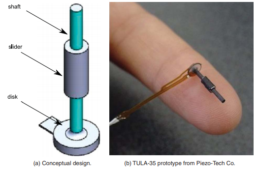
In order to overcome the compactness problem, the paper discusses the use of piezo-electric linear actuators instead. Here the actuator consists of a shaft, a moving slider and a piezo-electric ceramic disk. Its entirety is very small and lightweight as it is 2.4 mm diameter, 11.6 mm in length and 370 mg in mass. There are no burdensome relay levers that require the use of more space.

So the ceramic disk has a rigid case surrounding the transducer, which vibrates when voltage is applied. This creates vertical movement, allowing the slider and shaft to move up and downwards. The motion is based on the principle of inertia displacement by square wave electric potential [3]. Both the slider and shaft move upwards when the power is on, if it’s turned off then the shaft will be moving downwards while the slider remains at its global position due to its inertia. The power will be turned back on to move both the shaft and slider upwards and the power will be turned off again, which only moves the shaft downwards. Through this cycle we can move the slider and consequently move the pin up and down as the slider is attached to the plastic pin. The reverse motion can be achieved by simply inverting the cycle’s electric potential.
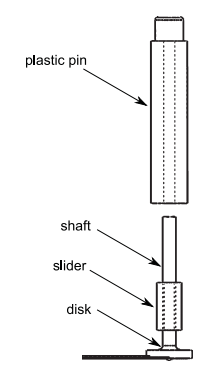
Here the assumption is made that the plastic pin is bi-stable. This means that we only require energy to changing one position from another. In order to acquire this, we assume that the friction between the slider and shaft is such that the slider retains its position without the use of power. To create an actual compact device with this mechanism, you would need the following design goals:
Each pin is independently addressed and their motion should not limit the motion of neighbouring pins
Each pin must be placed within a Braille cell and have convenient access to electricity without influencing other pins
Pins should be easily removable when necessary
The proposed design concept is to use multiple layers, where the first layer acts as the contact surface where pins will poke through and the second acts as a guiding structure for the pins. The consequent layers will have two pins each, while the bottom layer acts as a base of the cell.
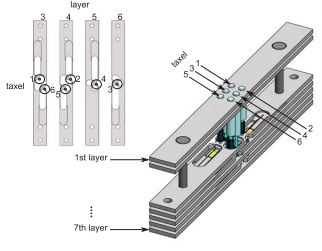
As a result, a prototype of this concept would have the following performance:
108 mN pull force
5 Hz refreshable bandwidth
0.7 mm strokes
The product is available through manufacturer quotes and not to the general consumer, so there is a wide price range and model variety. As of now, the rough estimate is around $50 per actuator which is quite expensive.
1. Tetzlaff, J.F.: Patent US 4283 178 A (1981) 2. Veláquez R., Hernández H., Preza E. (2012), A portable piezoelectric tactile terminal for Braille readers, Applied Bionics and Biomechanics 9, pp 45-60. Available at: http://downloads.hindawi.com/journals/abb/2012/637851.pdf 3. H. Ko, S. Kim, S. Borodinas, P. Vasiljev, C. Kang and S. Yoon, A novel tiny ultrasonic linear motor using the radial mode of a bimorph, Sensors and Actuators A 125 (2006), 477–481.
Electro-magnet actuators
To discuss the viability of electro-magnet actuators, we have looked at various existing patents from the literature study that utilize this mechanism in order to consider understand the core workings.
We see that the general use of electro-magnets is simple and take the portable reading device for the blind patent [1] as an example.

In the figure we see an expanded view of the housing concept for the Braille pins (19). These non-metallic pins (19) are attached to the plate (18) to keep them interdependent. The tips of the pins are always sticking through the holes (21) and form small dots. Large dots will be representing the actual Braille letters are moving cores (20) of micro-electromagnets (7) and its tip will be rounded. These moving cores (20) are hollow and crossed by the non-metallic pin (19), in order to allow the dots to remain protruding from the holes (21) when the mechanism is not actuated. When the micro-electromagnets are energized, the large dot made by the moving core (20) will protrude which causes the small dot to disappear. To reset the moving core back to the resting position when the micro-electromagnet is no longer energized, we can use a leaf spring that acts on a groove made in the moving core (20)
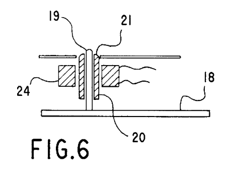
This actuator construction can be generalized as follows. The moving part is an axially magnetized cylindrical permanent magnet and there are two coils connected in series in such a way that they create magnetic flux of opposite directions in the region of the permanent magnet. Consequently, the permanent magnet will move either up or down depending on the polarity of the power supply. In order to move up, the coils should create flux in the air gap and to move down the polarity is simply reversed. This motion is transferred to the Braille dot using a non-metallic shaft to prevent magnetic interference.
1. Parienti R. (1999). U.S. Patent No. US6159013A. Available at: https://patents.google.com/patent/US6159013
Cam follower actuator
The mechanical linear actuator is the simplest actuator that would fit as a Braille mechanism, as it creates motion in a straight line. These typically operate by converting rotational motion into linear motion by using screws or gears. We consider the cam and follower assembly which consists of five basic parts; the groove, cam, follower, spring and pin. Here we create a toggled system that only has two states, where the pin is either protruding or not. As shown in the figure [1], the groove holds all parts, while the cam pushes the follower to the state it is not in. The spring is used to ensure that the follower can transition states every time the cam is active.
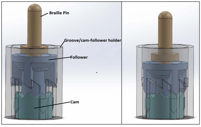
With the mechanism, we can disregard concerns of keeping active protruding Braille dots in place when the user is pressing on them while reading. Since the follower is resting on the cam’s grooves, it is locked in place until it is pushed by the cam.
1. Mubvuma T.H., Molter L., Alternative Actuators for Braille Devices. Available at: https://scholarship.tricolib.brynmawr.edu/bitstream/handle/10066/14255/Mubvuma_thesis_2014.pdf?sequence=1&isAllowed=y
Comparison
Linear piezo-electric actuators are the most compact and lightweight, but their high costs make it unreasonably expensive for a full display Braille product so we will not opt for this actuator.
Micro-electromagnets and cam followers are more accessible to general consumers than linear piezo-electric actuators and they are also significantly cheaper as the prices are around $10 per actuator. They do however take relatively more space, but this varies per actual product.
The main advantage of the cam follower actuator is that the protruding Braille dot state is very robust, as the user cannot force the dot down due to the locked grooves of the cam part. However, this can also be negated in the use of micro-electromagnets by having sufficient magnetic force keeping the dot protruding.
We can assume that the mechanism will be used very often, so by keeping the degradation of the performance in mind we can make the decision. The cam follower actuator uses mechanical parts that can degrade after many uses and are more prone to hardware failure. Meanwhile, the micro-electromagnets mechanism’s moving part is only dependent of the permanent magnet and the coils. Magnets generally remain magnetic for hundreds of years and its most prominent performance degradation factor is due to the reduction of its volume, which is not of a concern if we have working design. Here we don’t have many risks of hardware failures even after long extended uses and from the user’s perspective it would be preferable to have a longer-lasting product that highly unlikely requires repair in the future. Hence, we shall opt for the micro-electromagnet actuators for our Braille robot mechanism.
Actuator specification
As mentioned above, we will be making use of electromagnetic linear actuators but there are many different possible implementations with this mechanism. We will be considering the voice coil actuators and solenoids as they are both highly similar to the patent on micro-electromagnetic actuators for the braille display.
Voice coil actuators
Voice coil actuators or also known as non-commutated DC linear actuators consist of two assemblies. A permanent magnetic assembly, which contains the permanent magnets and ferrous steel and there is a coil assembly. As current flows through the coil assembly it will interact with the permanent magnetic field since it produces magnetic flux from the coil windings, which consequently generates a force vector perpendicular to the direction of the current based on the Lorentz force principle. This force vector can be reversed simply by changing the polarity of the current that flows through the coil. Either one of the assemblies can be used as the moving part in the voice coil actuator.
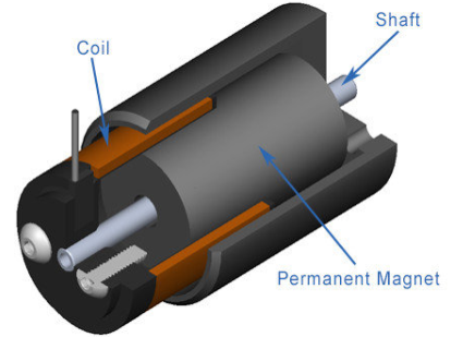
The amount of force generated can be expressed as F = k*B*L*I*N where
F = force (Newton)
k = force constant
B = magnetic flux density (tesla)
L = wire length (meter)
I = current (Ampere)
N = number of conductors
With a given voice coil, all the parameters are fixed except the current. Therefore, we can see that the generated force is directly proportional to the input current. This actuator is typical for fixed-stroke applications with maximum strokes of approximately 15 cm. The generated force is constant throughout the stroke, with exceptions of the beginning and the end of the stroke.
Solenoid
Solenoids consist of a coil contained in a ferrous steel housing and a movable steel slug. Here magnetic fields are generated by applying current to the coil, the magnetic field intensity is determined by the amount of force that can be generated by the solenoid. They can create high forces at much shorter strokes than voice coil actuators, however this operation is unidirectional and when the power is turned off the force drops to zero. In order to return to the opposite direction a spring is needed. Solenoids also have a rapidly declining force output throughout the total displacement and are therefore only typically used for strokes less than 1.5 cm.
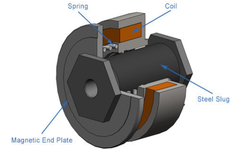
Comparison
When we compare the attributes of both actuators, we see that voice coil actuators have a constant force, the force is bidirectional and the stroke lengths can be considerably longer than solenoids. Meanwhile, solenoids can have higher force and operate with very short strokes that are within our range for the use of braille dots.
Our application only requires a compact linear actuator that is capable of accurately moving a shaft within the range of a millimeter and to be able to keep the shaft position fixed while there is a small downwards force applied on it (due to the blind person reading it). We cannot meet both requirements with the sole use of the actuator itself as the braille dot, therefore we would need these actuators to push a cam follower mechanism that puts the dot in a protruding state.
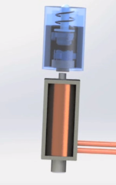
Knowing the fact that voice coil actuators usually cost more than solenoids and that solenoids are an appropriate solution to our problem, we have decided to make use of solenoids to change the states in the cam follower braille dot.
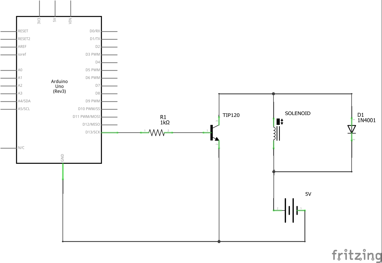
Technical specification for braille dot
1x Solenoid
- Model: ROB-11015 [1]
- Voltage: 5V DC
- Current: 1.1 A
- Power: 5.5 W
- DC Resistance: 4.5 Ohm
- Dimension: 20.00mm L x 11.00m W x 12.00mm H
- Stroke length: 4.5 mm
- Shaft diameter: 4.0 mm
Despite the 5V, it cannot be powered from the Arduino as it draws too much current and when it’s turned off it produces destructive voltages. Therefore we will use an external 5V power supply.
1x 1k Ohm Resistor
Arduino Uno can pass a maximum of 40 mA from a pin.
1x 1N4001 Diode
Only allows current to flow in one direction in order to prevent frying the Arduino when the current is turned off.
1x NPN Transistor
- Model: TIP120 [2]
- Collector-Emitter Voltage Max: 60 V
- Emitter-Base Voltage: 5 V
- DC Current Max: 0.12 A
1. Solenoid ROB-11015 datasheet from sparkfun https://cdn.sparkfun.com/datasheets/Robotics/ZHO-0420S-05A4.5%20SPECIFICATION.pdf
2. NPN transistor TIP120 from adafruit https://cdn-shop.adafruit.com/datasheets/TIP120.pdf
Material study
For materials we’ll first look into materials which can act as a cover over the pins of the robot. For this to be possible, the material would need to be sufficiently elastic. With this approach we aim to provide a good user experience which might be hindered by the spaces and inconsistencies that a non-elastic braille display would provide. This inconsistencies might be created because of faults in the connection between the braille display and the pins or unintended deformation of the braille display. Based on the feedback we’ll receive from our interviews, we might look into the non-elastic materials. Materials For the materials regarding the display of the article, we’ve done some research as to which materials would be useable. Since the exact requirements of the materials are not yet calculated, the requirements will mostly based on estimates. The requirements of the materials are that they are sufficiently elastic, easily deformable, durable and have a low friction coefficient. We distinguish between the following material types: Metals, Polymers, ceramics and textiles.[1] For each of these material types we’ll discuss what they include exactly and if applicable which materials could be useable . Since both deformability,durability and friction coefficient are not easily specified, we’ll focus on the elasticity.
Metals
Metals refers to a group of materials that that consists of elements that readily forms positive ions and has metallic bonds. In general, metals conduct electricity and heat relatively well and are overall a popular material type to use. Depending on the type of metal, they could be easily deformable and in our situation durable. The main problem with metals regarding our robot is that in general their elasticity is low. This means that if the material is deformed too much, it will not revert back to its original form. We assume our design would need a decently high elasticity and for these reasons we’ll look into the metals with the highest elasticity. We found the following metals:
Chromoly steel with Cr <= 9%
Chromoly steel is an alloy including both chromium and molybdenum. Chromoly is often used when the strength of mild carbon steel is not enough. You often see this material used in things such as bicycle tubes, molds, pins and chain links. Cost: $0.06 – 0.15 / kg Elasticity: 29.7* 10^6- 30.9 * 10^6 psi [2]
Carbon steel
Carbon steels refers to a steel which contains carbon elements up to 2.1% of its weight. Carbon steel has many different uses based on the percentage of carbon. The higher the percentage of carbon, the stronger the material is. Because of this carbon steels has a range of uses from constructing small things such as fences to construction of buildings and bridges. Cost: $0.86 – 1.03 / kg [4] Elasticity: 29.3* 10^6- 29.5 * 10^6 psi [2]
Polymers
A polymer refers to a type of material in which the material is made from long chains of molecules which may have cross linking bonds affecting flexibility and stiffness. Polymers can be categorized in three different categories. The first category is thermoplastics. Thermoplastics refers to a polymer which can only be flexible or moldable above certain temperature. The thermoplastic with the lowest moldable temperature is 60 °C. Since the temperature is too high for long term exposure to the skin, we can conclude that there are no thermoplastics which can be used for our robot. The second category is thermosetting polymers. Thermosetting polymers refers to polymer which is irreversibly hardened. Once hardened the thermosetting polymers cannot be changed in form. For this reason thermosetting polymers are not usable for our robot. The third is elastomer. Elastomer refers to polymers that are capable of recovering their original shape after being stretched or deformed to great extents. This polymer type can be used in our design because of its high elasticity. A good choice for the material for our design would be a certain type or rubber. Rubber is an easily obtainable material and because of its general high elasticity, it could be used in our robot. The main problem with using rubber is that rubber generally has a high friction. When the user would use our robot to read over the letters, the high friction will most likely cause a bad experience for the user. This could be solved by applying a low friction rubber coating to the robot to reduce the friction coefficient. Cost: $ 3.46 / kg
Ceramics
Ceramics are solid materials which are composed of inorganic compounds of metal, non-metal and covalent bonds. Ceramics are hard materials which are known to have an even lower elasticity at room temperature than most metals. Because of this, we will assume for now all ceramics will be unusable for our robot.
Textiles
Textiles are any material ,which can be used to create fabrics , cloth or the resulting material. An example of textiles are cotton or wool. There exists multiple kinds of textiles in which each of them has his own characteristics. Depending on how the materials are created, textiles could be elastic and thus be used in our robot.
A good candidate for our robot is the textile wool. Wool is a fibre formed of sheep fur which is both elastic and durable. Since wool made up of multiple threads, there could be some hindrance when reading the braille points. This is because threads will have to be spun and thus will not be a perfectly flat layer. This will have to be tested with the users in order to verify the viability of this material.
User Requirements
This is being worked on iteratively by processing survey results into requirements and we will be checking those requirements with the target group as well. It can be found at: https://drive.google.com/open?id=1D0T3C2wYtNyWK7ZE4wtTIpXq9gRA280T4eBAQZk00WI
User Interface
The UI will be based on survey results we have conducted along with iterative improvements made to this over time as we constantly update this according to the feedback we receive. Here we discuss the workings of each interface without going into too much detail about the actual implementation, as each interface is prone to change. Finalized interfaces will have a state diagram/flowchart that shows its relations and functions.
Automatic display refresh [R_003]
Using refreshable braille displays for reading books is uncommon, as the experience is not very pleasant due to slow refreshing and the tedious work of manually refreshing the display. Books with more pages naturally require even more manual refreshing, which can take the user out of his/her reading flow. By including a sensor that detects whether the user has finished reading the last braille letter in the display and then consequently refreshing the letters such that it shows the next sentence we greatly improve on user friendliness. However, it can be crucial to decide whether we refresh by letter or the entire display as well as if the user is actually done with reading the sentence.
Refresh per letter
Once the user has read a braille letter x and is for example 4 letters further, we can assume that the user will no longer notice nor feel the presence of letter x. Therefore we will update this letter x according to its next sentence and since we have 20 letters, it is safe to assume that the letter has been updated before the user reaches it again. We will however require sensors that track the current reading position of the user.
Full display refresh
Due to the possibility of users that re-read certain letters in a sentence, we don’t want refresh per letter in that case so we will only refresh the entire display once the user has reached the very last 20th letter. Depending on the actual refreshing speed, this could potentially cause the user to wait instead of seamlessly allowing the user to continue reading. However, it is more robust and people are used to this method from manually pressing a button to advance to the next sentence.
Dependencies
This proces should only be executed when the Autonomous toggle is enabled [R_002] and we have overlap in functionality due to the manual Advance button [R_001]. So we have two options for how we handle this overlap:
Advance button becomes disabled; the user can only make use of the automatic refresh and are purely dependent on it.
Advance button overwrites automatic refresh; when the Advance button is pressed it performs its function and the automatic refresh gets disabled until the advance proces has been completed in order to avoid double refresh.
UI layout [R_001, R_002]
Due to the functional simplicity of only acting as a e-book braille reading device, we won’t be needing many functional operations for our users. The most important one is to advance to the next braille sentence through either manual or automatic operation. So we will be having the following buttons:
Autonomous mode toggle
Advance button
As both buttons are provide the same functional operation in different ways, we do not want the user to accidentally overlap with interacting to either button. Therefore we shall be placing the toggle on the side of the device, which has a small surface of searching for the toggle. And due to its position, the user will have no risk of accidentally turning the toggle while reading.
As of the Advance button, it should be placed such that it conforms to the use of either left/right hand users as well as those who use both of their hands to reach. In all of those cases, the button generally can be reached easiest with the thumb. So we will be placing the Advance button centered below the braille display. However, to avoid hinderance caused by this button during reading, we will be placing the button at a larger height than the button. The Advance button will be integrated in a wristrest that provides optional comfort to the user.
Braille to Arduino
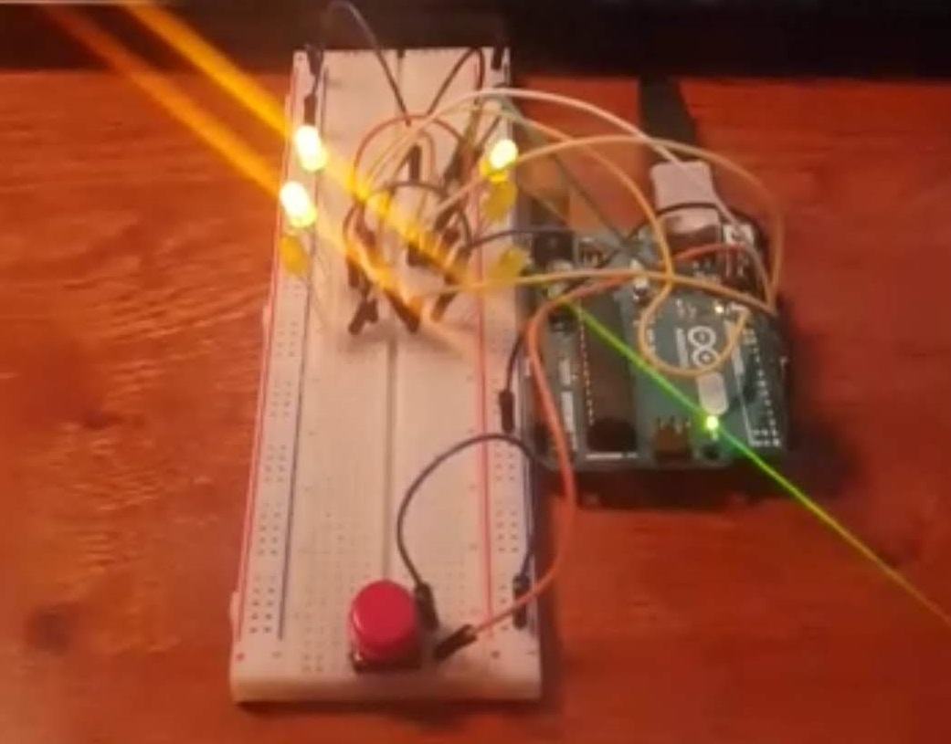
We're using an Arduino Uno with 6 outputs which represents a braille character. For testing purposes, we'll be using LEDs for these 6 outputs. Serial Monitor is used for input. Enter the numbers of the LEDs you want to enable (eg. 1256). After you press “send” on the interface or “enter” on your keyboard, the lights corresponding to the number input will light up. We've also added a button and by pressing it, you can reset all lights (the Braille output).
Defining the output of Arduino to Braille
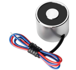
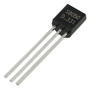 An electro magnet (suited for Arduino) can be turned on and off via a digital pin. The current through the Arduino itself is too weak for it to operate, so we need an external power supply (battery). Then, to regulate the voltage we’ll need a transistor.
Alternatively, we can also use relays. The Arduino would power the On/Off action of the relay and an external power supply can power the magnet.
We’ll need 6 electro magnets, 6 transistors (or relays if we go for that option), and one battery.
To reverse polarity of an electro magnet we can use the transistor, simply switch the output of the two transistor pins.
Serial communication between Windows and Arduino
We’ll be using Serial communication to connect our Windows software (PDF to binary output) to our Arduino software (binary output to solenoid). And in order to do that, we’ll be using the following library. https://sourceforge.net/projects/javaarduinolibrary/ As we do not have all the parts yet for the solenoid, we’ll be using LEDs for now. It’s the same principle.
We can for instance send an output of 111000, it will be communicated to the Arduino via the Serial port, and the Arduino will enable the first 3 of the 6 LEDs.
Solenoid & Serial communication testing
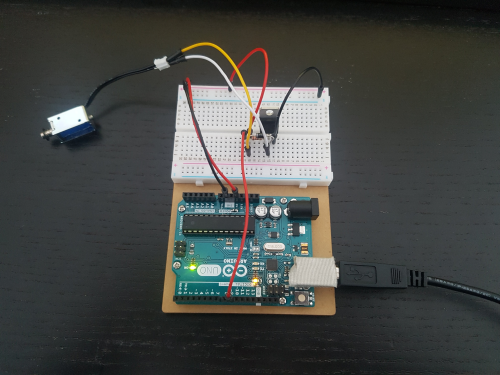
We have acquired a single solenoid for testing purposes. Our main goal was to find out if the solenoid we got was of good quality and if the strength of the solenoid was sufficient (can we push it down “accidentally” while reading?), before we invest in 6 of them. We did at first get a faulty solenoid, but the second one we got is perfect. After a lot of testing we could conclude that the solenoid is powerful enough and works reliably.
We have made a program to test both our solenoid and serial communication, while also gaining some more experience with GUIs (which will be used in our final product).
To connect to the Arduino from Windows, we have made a port selection GUI. Select the COM port, and click on connect.

We have added two simple functions: “Pin up” and “Pin down”. These buttons control the state of the solenoid.

The single solenoid testing setup.
We’ll be buying 5 more solenoids next. (for complete braille input we require 6 pins)
3D modelling the mechanism
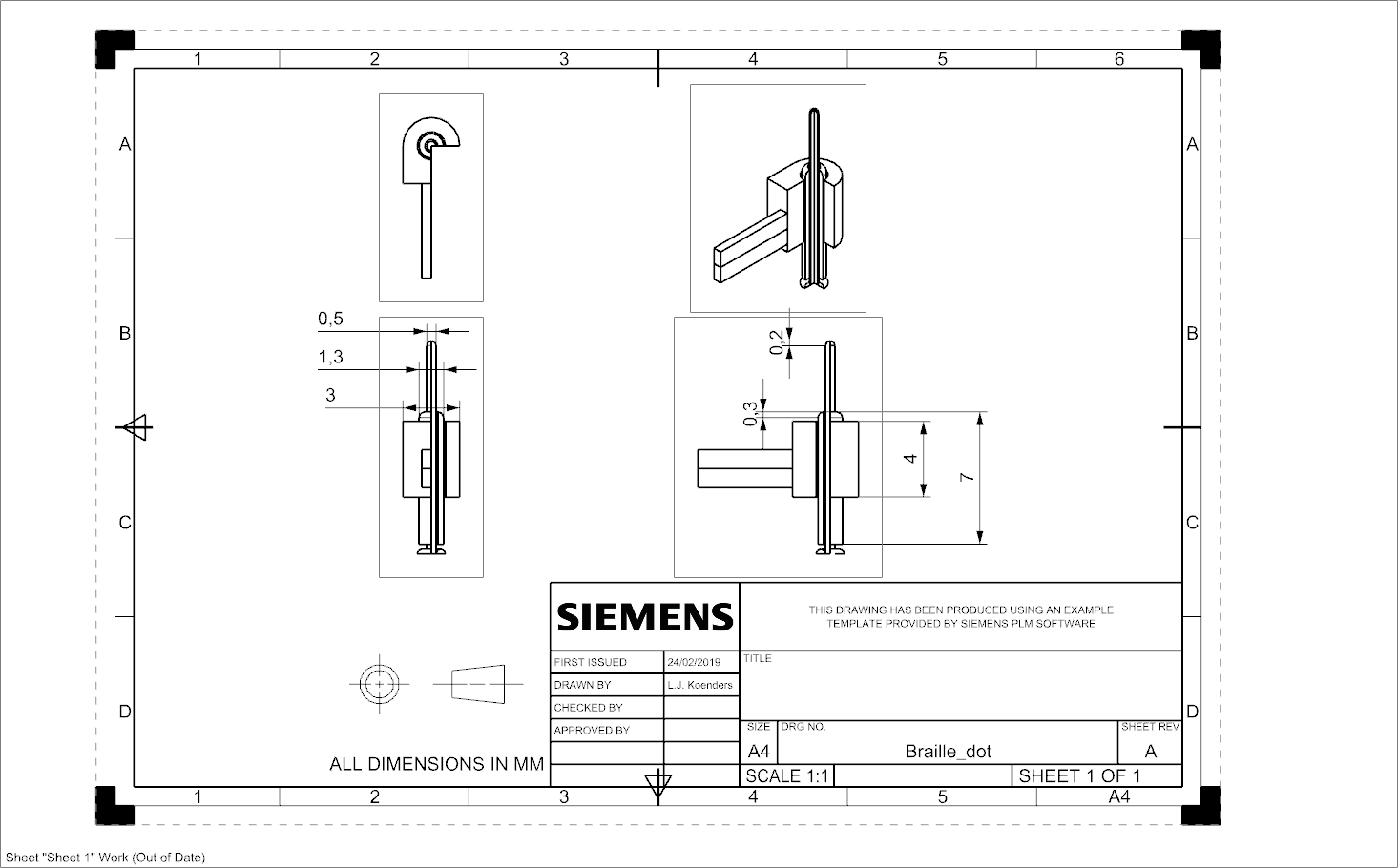
For the 3D modelling of the mechanism, several iterations will be made of different ideas. The model will keep changing because used methods or components will change. First a single dot of a braille letter was modelled, using some assumed dimensions for the parts. The technical drawing of this model can be seen below as a section of the complete pin.
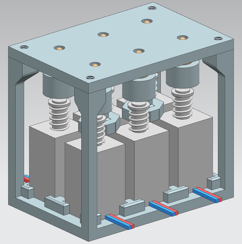
Then, six of these dots were used to model one complete braille letter, as is one of the goals for the end of the project. However, the model changed because we chose to use a different mechanism. The whole model was made from scratch, to include a solenoid mechanism with a cam and follower. This model can be seen below.
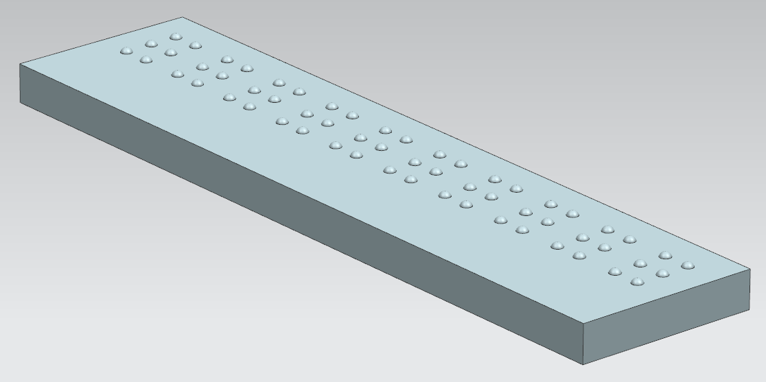
Also, a model was made of a pad of arbitrary length with several letters next to each other. This could be used for the dummy, but is also a help to visualize how much space we will have. The eventual length of the pad will be decided upon when the user-requirement list is set up.
braille dot distance research
The braille standards are different all around the world. The exact reasoning for these standards are nowhere to be found, however there was an article about how much you can feel with your body, which found out that the human finger is able to detect objects of a size of 2.3mm. Most values of the braille standards had a distance of between dots for around this value. While I did not find any further research to support my claim, I believe that the dot distance is based on this found value. Because I can not find what the exact reasonings for the differences between the values are, I suggest that we go for the electronic braille standards since we our robot falls within this category.
https://www.pharmabraille.com/pharmaceutical-braille/marburg-medium-font-standard/ https://www.ncbi.nlm.nih.gov/pmc/articles/PMC3928539/ https://cdn.discordapp.com/attachments/140133975606689793/557703767332618260/Meier_FootFeedback_iWOAR2015.pdf
converting a pdf file to braille code
Using http://braillebug.afb.org/braille_deciphering.asp for general braille rules.
We can describe a 6-pin braille symbol by the position of the ‘active’ pins. In order from top to bottom and then left to right. We can represent this as a boolean vector or equivalent binary number. The symbol ‘a’ for example becomes 100000.
Conversion rules:
- Each letter in the alphabet and some symbols are converted to the corresponding braille code. (using a table)
- A capital letter is made by adding 000001 in front of the normal code.
- A capitalised word is made by adding the 0000001 symbol twice before it. (what if the only non-capitalised symbols in a word are not letters?)
- A number is made by placing 001111 in front of the symbols for the letters that correspond to the digits. For example a=1,b=2 so 12 = 001111 100000 110000
- 000011 must be placed between a number and a letter if the letter directly follows the number
- Some groups of letters get contracted to a single symbol or multiple (but less) symbols. (using a table)
Currently we have written a program in java that accepts a pdf file and outputs a txt file with the text translated symbol by symbol to braille. The braille is encoded as described above.
TODO: Apply word context dependent rules including the number and letter prefixes. Add a way for the user to supply character translations so that things like language specific translation can be added when needed. Pass the translation to the arduino.
V2
DONE: Segregation into words. Word specific number and letter symbols. Contractions for full words, prefixes and suffixes. A full list of these is not implemented and has to be provided, what kind of contractions people want to read also differs from person to person (grade 2 and grade 3 braille).
PROBLEMS:
- Complicated grammar rules like mentioned in https://en.wikipedia.org/wiki/English_Braille :
“When there are several ways to write a word, the shortest one is chosen, and when they are of equal length, the one without (two-cell) abbreviations is chosen. So, thence is written th-ence (3 cells) rather than the-n-c-e (4 cells). However, with the sequences -anced, -ancer, -enced, -encer, the form with -ance/-ence is used even if not shorter.” “In general, these are acceptable as parts of longer words as long as they retain their pronunciation”
Some of these could be practically impossible to implement, for example when pronunciation is mentioned.
- Currently capitalized parts words are not contracted unless this part is also capitalised in the list of contractions used by the program. (this could actually be the desired behaviour)
- Contractions containing punctuations symbols cannot be recognized right now because they are not considered part of the word. (luckily I don't think these exist)
We are choosing to ignore the more complicated situations since we do not even know if most people can read these kind of contractions.
description of the algorithm
- The algorithm looks for the next word in the text. A word is a sequence of symbols which is between 2 symbols that are not alphanumeric (e.g. punctuation and whitespace)
- All symbols that are between this word and the previous word are translated to the corresponding braille symbol (punctuation and whitespace)
- A table is used to look for possible contractions for the whole word, a prefix or a suffix. The contracted part of the word is then removed an*d the contraction is saved.
- The rest of the word is translated symbol for symbol while also adding the symbols indicating capitalization and numbers.
Dummy
In the next section we’ll split the parts of the dummy into two categories.
The display
The first part is the braille display. The braille display refers to the way we’re going to display braille. This could be done with either providing a solid plate in which braille is already displayed and simply using that or a mechanisms which display’s the braille. This mechanism could for example be manually pushing the pins to create a braille display. Depending on the depth of which we want to test, there are multiple options to create the braille display.
The first option is to create a very basic braille display dummy. This dummy would be similar to a solid plate, which contains braille, and could be attached on top of the casing of the robot. This form of braille display will be relatively simply and will ignore the user preferences for material types or other preferences such as a button and focus more on main interactions. These interactions will be purely based on what they think of the idea and what they would improve. This option would be sufficient in case you want to verify the intent of your product. In case you want to test multiple things such as user preferences for example materials or buttons, this option might be insufficient. On another note, this option might be sufficient as a base dummy in which you can extent later on. For example it might be possible attach the materials which you wish to test into the basic braille display or to create buttons at the end of the display. However, depending on the design of the display, extensions might have a low quality.
The second option for the braille display would be to design a display similar to the previous one, but instead design it with these extensions already included. In other words, a braille display consisting of a to-be-tested material which contains braille which is changeable. This could be done in either two ways. The first one would be to create a display on which the materials can be attached upon in such a way that the readability of the display is sufficient. This method would allow for easier testing since both materials could easily be changed and it allows for reusability of the braille display. The main problem with this method would be the technical problem, in which you have to create a mechanism with a loosely coupled material who ensures sufficient readability. The main problem with the readability would be the that the material would simply be pushed up completely by the braille pins since it’s loosely attached. This problem would could be solved by making the material more attached to the braille display, however this method might then lose its purpose depending on how tight the attachment is.
The second method to achieve this option would be to create the multiple displays in which the to-be-tested material are integrated. In these displays, the materials would be strongly attached to the display. This method does not suffer from the problems that the previous method does. This method instead uses more materials, as multiple displays have to be created. Additionally, due to the aforementioned reasons, the reusability of the display is lower.
The dummy is 3D printed to have a physical product. The top part of this is already finished, which is shown in the figure below.
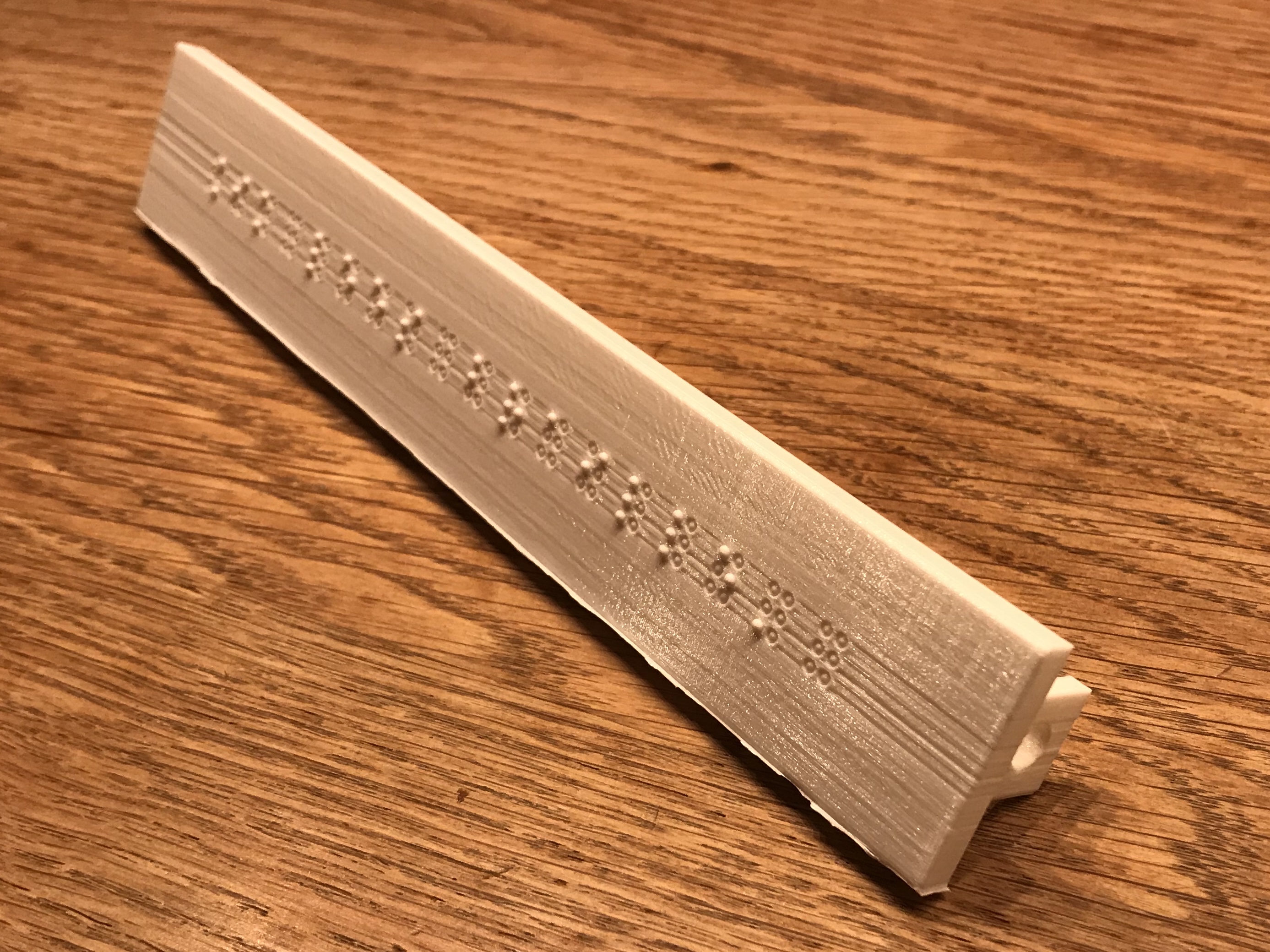
The casing
The second part of the dummy will be the casing. This casing refers to the outside of the dummy which is used to provide an estimate of the size of our robot and a base on which the other parts will be attached to. Since we focus more on the reading aspect, for the base a simple box would be sufficient. The dimensions of this box will most likely depend on the needed estimated space for the hardware and the size of the braille display. An important thing to take into consideration when creating the casing, will be to consider interaction between the braille display dummy and the casing itself. For example in case you want to change the letters of braille on the display, the casing should allow for a display to be removed and reattached.
Sources for materials
[1]https://www.the-warren.org/ALevelRevision/engineering/Materialclasses.html
[2]https://www.engineeringtoolbox.com/young-modulus-d_773.html
[3]http://burncentrecare.co.uk/about_burned_skin.html https://www.orfit.com/faq/what-are-low-temperature-thermoplastic-materials-lttps/
[4]https://agmetalminer.com/metal-prices/carbon-steel/
http://www.campaignforwool.org/about-wool/
http://bieap.gov.in/Pdf/CGTPaperII.pdf
https://global.kyocera.com/fcworld/charact/strong/rigidity.html
https://www.engineeringtoolbox.com/ceramics-properties-d_1227.html
http://www.dynacer.com/properties/
http://www.newworldencyclopedia.org/entry/Elastomer
https://www.britannica.com/science/elastomer
https://en.wikipedia.org/wiki/Thermosetting_polymer
https://en.wikipedia.org/wiki/Thermoplastic
https://www.onealsteel.com/carbon-and-alloy-steel.html
https://www.metalsupermarkets.com/what-is-chromoly/
https://www.economicshelp.org/blog/301/concepts/understanding-elasticity/
