PRE2017 3 Group 17
The simulation
Now that all decisions have been made and requirements have been set, it is finally time to work on the final product. As we have decided not to work with real drones, it is necessary to create a medium through which we can show how the drones would operate and react with the environment if they were deployed in the real world. The chosen medium for this will be a simulation. This means however, that in addition to creating the program used to navigate the drones, it is also necessary to create an interface and simulation through which to interact with the program. Even though creating two separate programs would be more realistic, it would also be many times more difficult to implement. Therefore it was decided to put both in the same program, but restrict the communication between the simulated drones and the model, such that it could be decoupled quite easily.
In our simulation one can place workers, objects and walls to see how drones react to them. This is in addition to sending drones which would be available in an interface used for the algorithm if it were used in a stand-alone application. The simulation however does not take into account where the drones are and where they will be going when placing such walls, objects and workers. This was done because in reality workers will not know where drones are going either and drones should react to them going somewhere rather than the other way around. They can be placed on the same spot as where a drone is although this would not be something that happens in reality since such things do not just appear out of thin air.
Decoupling
The drones in the model and in the simulation are not directly connected. The "real position" of the drone is not known precisely at all times by the model, and is only updated once a drone hits a node to reflect this behaviour. As the model passes fly paths to the drones which they directly follow, the model does know all fly paths of all drones.
To prevent drones from flying over the same edge, the model 'locks' and 'unlocks' an edge in a similar fashion to how Mutexes work. When a drone wishes to enter an edge, it asks the model to enter the edge. If it is not allowed to do so by the model, the drone will wait. Once the drone is allowed to pass, the model locks the edge, preventing other drones from entering the same transition. Once this drone leaves the edge, the model unlocks the edge again, allowing other drones to move through it again.
The model receives an update when a drone detects an obstacle. This update includes whether the drone detected a permanent obstacle (E.g. wall) or a temporary one (E.g. scaffolding). The model then locks the respective edge containing this obstacle for a specific amount of time, based on the detected obstacle. This way, no drones will pass (or even try to pass) the respective edge.
The model can adjust the fly path of a drone at any time. For example, a drone's fly path can be adjusted when some paths are no longer locked and provide a faster route to the drone's destination.
The interface
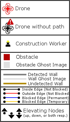
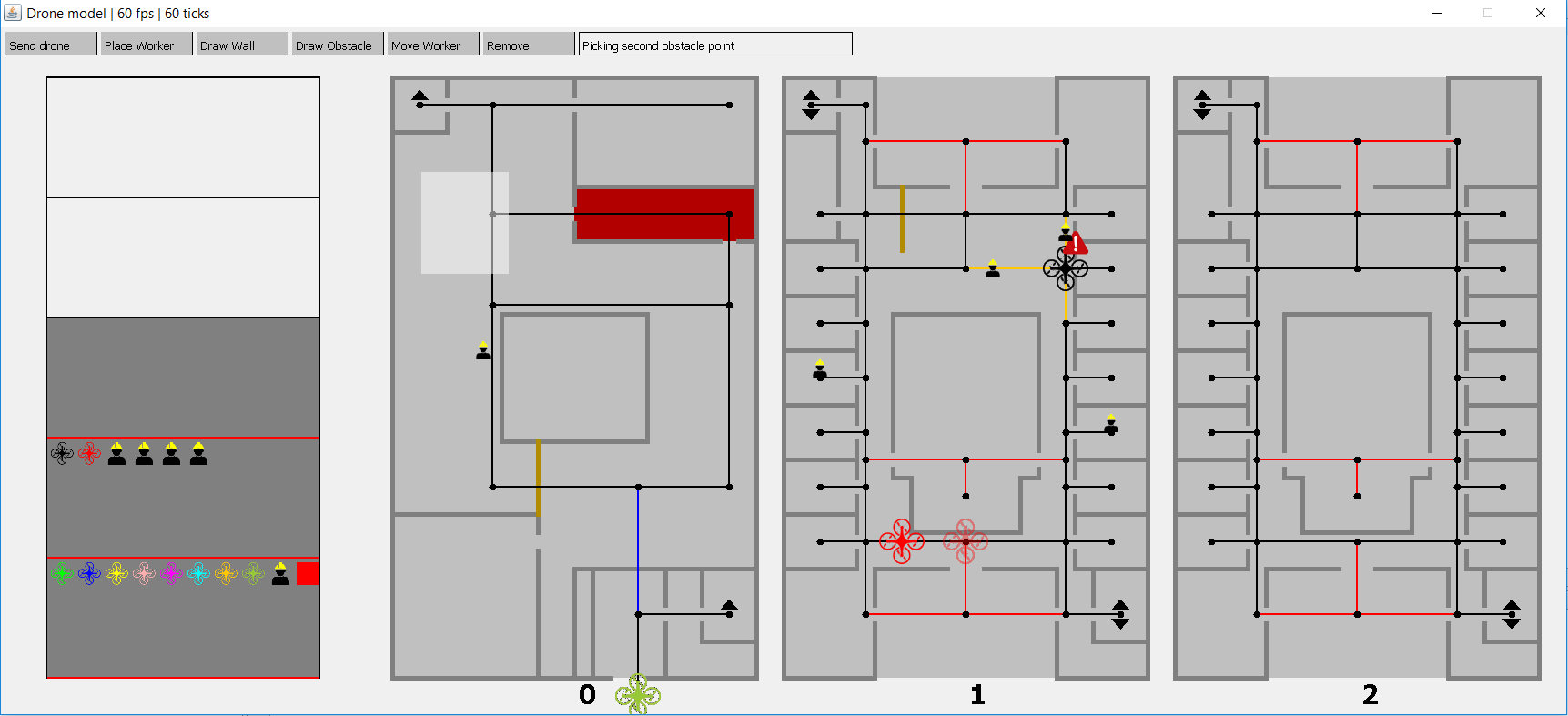
Here a screenshot of the main interface is shown together with an index indicating the meaning of what can be seen.
Below we will explain more about this interface and interactions possible in it.


Interaction
Mouse Buttons
In Model, most of the elements from the model where explained. So for the full explanation it is advised to also read that section. On top six buttons are visible, which are also available in the menu you get when right-clicking on the model:
- "Send drone": A drone will be deployed after selecting a node with the Left Mouse Button. (When using the option in the right-click menu, the drone will be deployed to the location from which the menu was opened instead)
- "Place Worker" places a Construction Worker. Workers act like similar to obstacles, but unlike those they have a fixed size and are able to move.
- "Draw Wall" requires two button presses afterwards; the starting point of the wall and the endpoint of the wall. (When using the respective option in the right-click menu, only the endpoint needs to be selected). Walls can only span a single floor at the same time. If drawing a wall would violate this principle, the action will be cancelled. Drones cannot fly through walls, and will mark edges passing those as 'Permanently blocked'. While drawing a Wall, a Ghost Image of it appears to indicate where the wall will be placed. If attempting to move the endpoint to an invalid area (E.g. another floor), the ghost image will snap to the latest valid endpoint to indicate this.
- "Draw Obstacle" places an obstacle. Placing is done the same as placing a wall, and follows the same rules too. Drones cannot pass obstacles, and will mark edges passing those as "temporarily blocked". This temporary block will be removed again given some time. This time will be longer the more often this edge has been blocked.
- "Move Worker" moves a worker. A worker needs to be selected first, and a destination can be picked afterwards. (When using the option in the right-click menu, only a destination needs to be picked.) A worker cannot walk through walls, and is as such able to navigate complex mazes!
- "Remove" removes all temporary obstacles at a given location, such as workers. Walls cannot be removed, as those are permanent.
- Scrolling up will shift your view a floor up (if possible), and scrolling down will shift the view a floor down (if possible).
- The status bar is empty most of the time, but when the simulation is paused etc. the program will inform the user through this box. It also informs the user what to select when using any of the above options.
Keyboard Buttons
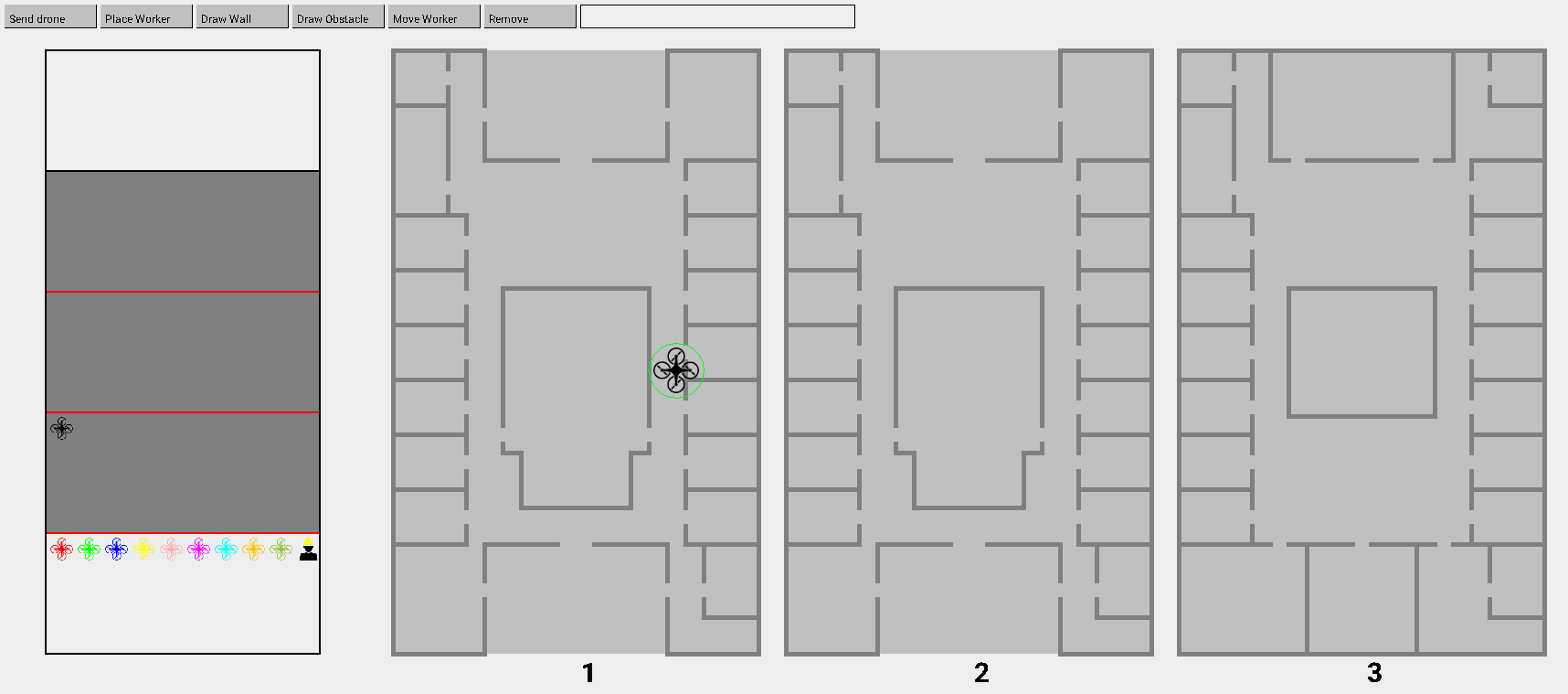
- "m" toggles the model, when the model is off, the elements described in Model will disappear as can be seen in the second image below.
- "r" restarts the simulation. Since walls are permanent, this is the only way to remove them without stopping the simulation.
- "escape" cancels any action that was active, so for instance if you did not press a second time when placing a wall the action can be canceled by pressing this button.
- "p" pauzes the simulation. Time will freeze.
- "1", ..., "6" correspond with the mouse buttons
- "->" will shift the top down view one to the right
- "<-" will shift the top down view one to the left
Display of the Floors
A side-view of the building can be viewed at the left of the screen in the simulation. It gives a clear overview of on which floors the drones, obstacles, and detected workers are.
Furthermore, since the UI only has place for the top-down view of three floors, between which can be scrolled, it should be clear which floors are currently visible. This is made clear by the floor numbers under each top-down view, as well as by highlighting (with a darker shade of grey) which floors are visible on the screen in the side-view.
Drones
Drones are drawn as quadcopters in this simulation and have a flying animation. Each drone also has a green circle around it, which is the detection range. A drone is not omniscient according to the assumptions, so when a object is in the way the drone will detect it only if it is in this circle. If the model layer is on, like the first image below, the program shows a semi-transparent quadcopter in the place where the model got the drones last location.
If the model no longer can find a path for a drone, this drone will be marked with an alert sign as can be seen in the screenshot above. This is to indicate to the person controlling the simulation that the model is unable guide that drone to its destination.

