Embedded Motion Control 2017 Group 4
Reports
Group 4
| M.R.M. Beurskens | 0843080 |
| N.H.J. Janssen | 0842075 |
| M.C.W. Schouten | 0869793 |
| J.A.E. Verest | 0844791 |
| M.S. de Wildt | 0776941 |
| R.H.M. Winters | 0854048 |
Initial design
Introduction
In this design chapter, the initial design of a maze solving robot is specified in terms of requirements, specifications, components, functions and interfaces. It is implemented on the PICO hardware platform. A task-skill-motion framework is used in order to describe the robot behaviour. This will also be implemented in C++.
Requirements and specifications
PICO is required to autonomously navigate through a maze and find the exit without bumping into any of the walls. A door will be present in the maze, and must be opened by "ringing the bell" in a suitable location whilst standing still. Open spaces might be present, and the walls are approximately axis aligned. The maze might also feature loops. Therefore PICO is required to do the following:
- Recognize walls and corridors in a robust manner. The walls are axis aligned, however not perfectly. PICO should allow for an alignment error. It also has to stay away from the walls with a sufficient margin (e.g. 10 cm between robot and wall). Bumping into a wall will count as a failed attempt.
- Identify possible "door areas" in a robust manner. "The door will be situated at a dead end, a dead end being defined as a piece of wall with minimum length 0.5 meter and maximum length 1.5 meter with side-walls of at least 0.3 meter length". Alignment errors again need to be taken into account.
- Map the maze to determine whether the area has been visited and to build a world model. Odometry and a Laser Range Finder (LRF) are used to build a world map and determine the location in the world. The odometry and LRF data should be synchronized to avoid drift in world location and mapping (SLAM).
- Recognize corners as nodes in order to build an abstract and simplified maze representation consisting of nodes and lines.
- Cary out a maze solving strategy based on its world model and solve and execute corresponding routing. The solving routine and the routing should be able to handle loops and open spaces and are based on the simplified maze representation. This enables more general strategy composition and faster computation.
- Open doors by ringing a bell in the door area. No part of PICO should be located outside the 1.3 meter range of the door and PICO should be standing still whilst ringing the bell. The door opens completely within 5 seconds after PICOs request. Once the door is completely open, PICO needs to pass the open doorway to find the exit of the maze.
- The software should be easy to set up and deploy, i.e. using git pull and with a single executable.
- Clear the maze as soon as possible, with a total available time of seven minutes for two attempts. A maximum speed of 0.5 m/s translational and 1.2 rad/s rotational is given.
- Do not stand still for more than thirty seconds when inside the maze.
- Recognize when the maze is solved.
Components
Pico features a Laser Range Finder (LRF) to detect surrounding obstacles and wheel encoders to measure odometry data. The wheel base is holonomic, enabling it to turn on the spot and drive in any direction. An emergency button is present on the remote. PICO runs on batteries and should always be charging when not driving around.
The software runs on an Intel i7 processor running Ubuntu 14.04 LTS. The Robotic Operating System (ROS) is used as a framework for PICOs software. However, an intermediate software layer is provided which can be used to access sensor data and actuate the robot. Our own software layer is divided into five main components: actuation, sensing, world model, task manager and skill.
Functions
Configuration file
- Configuration: Defines a number of parameters. This is a header file so no inputs or outputs.
Actuation
- Move: This function calculates the translational velocity in x and y direction and the rotational velocity corresponding to the direction vector and net velocity outputted by the path planning function. The calculated velocities are sent tot the base actuators.
- Input: Direction vector, total velocity, Output: -.
- Stop: Stops the robot by sending the base velocities of magnitude zero.
- Input:-, Output:-.
- Rotate: Rotates the robot 90 or 180 degrees. First checks the robot has enough space to rotate without hitting the wall. If this is not the case, first a call to Move is made to move the robot away from the wall.
- Open door: Makes sure the robot stands still, rings the bell to open the door and waits until the door is opened.
- Input: LRF data, Output: -.
Sensing
- Get LRF data: Gets the data from the laser range finder.
- Input: -, Output: LRF data
- Get odometry data: Gets position data from omni-wheels.
- Input: -, Output: odometry data
World Model
- SLAM: Simultaneous Localization And Mapping, this updates the position of PICO in the world model using new sensor data.
- Input: LRF data, Odometry data, Output: World model
- Object recognition: This function will estimate which objects there are in the World Model using the geometries of the environment.
- Input: World model, Output: Objects with their coordinates.
Task Manager
- Task monitor: Determines which piece of code will be executed next.
- Input: -, Output: -
Skill
- Filter data: Moving average filter to minimize noise.
- Input: noisy data, Output: averaged data.
- Finish: Recognizes that the finish line has been crossed and that Pico can stop searching for the exit. The main script can be terminated.
- Input: World model, Output: -
- Strategy: Gives a general direction based on the maze solving algorithm that is chosen.
- Input: World model data, LRF data. Output: Target point.
- Path planning: Uses an Artificial Potential Field to output a direction vector considering the target point outputted by the strategy function and the LRF data.
- Input: Target point, LRF data. Output: Direction vector
Interfaces
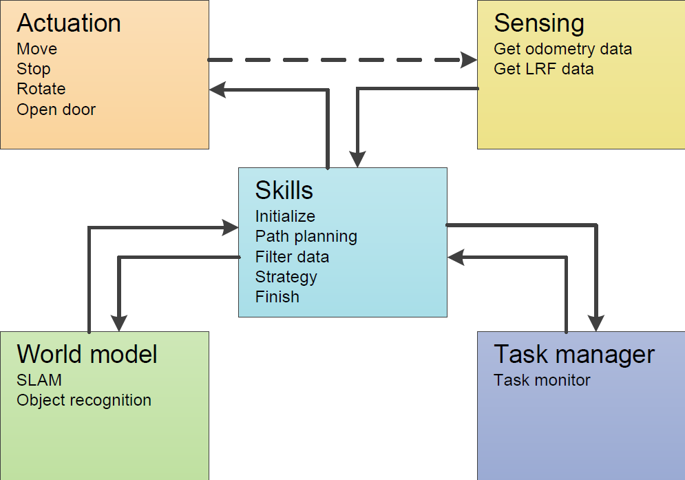
The software functions have multiple inputs and outputs and can be grouped by functionality. If data from the sensing component is used by a function from the skill component, the data is transferred between these components, this is referred to as an interface. A rough overview of the interfaces is shown in Figure 1. The dashed line represents that the actions of the robot will influence what the sensors measure.
Corridor Challenge
Repulsion & Angle correction
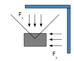
The first thing that was considered for the corridor challenge was some kind of repulsion from the walls to make sure Pico does not bump into anything. For the repulsion a simple version of an Artificial Potential Field is considered, which is given by the formula below
[math]\displaystyle{ Insert formula here }[/math]
For a range laser data in front of Pico, this formula is used to calculate a force Fx in the forward direction. To get a force Fy in the side ward direction, the other laser range data is used. The resulting netto forces are scaled and then used as input for the actuation. Note that if the laser sees something at a very large distance or does not see anything at all, the returned distance is very small or even negative. Therefore all distances smaller then 0.01 meter are set to 10 meter.
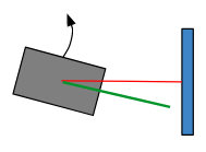
For the angle correction all the laser data at the right side of Pico is considered. The smallest distance to the wall and the corresponding angle are found using a for-loop. After subtraction of 90 degrees, the resulting angle is used as input for the desired rotation speed. This approach can be interpreted as a torsional spring connected to Pico.
Actuation
World model
Making the turn
Driving between two walls can be easily done using the the actuation, repulsion and angle correction code. To actually make a turn at the right moment to drive into the corridor, the corridor has to be recognized. From the world model, corner nodes and end nodes are received. If a corner node is recognized at the right or left of Pico (approximately 90 degrees) and if the distance to this corner node is reasonable, the distance to the closest next corner node is used to calculate the width of the corridor using the cosine rule. If no other corner node is recognized or this corner node is to far away, the distance the the first corner node (which is in this case seen at the right of pico) is taken as the corridor distance.
Final design
Interface
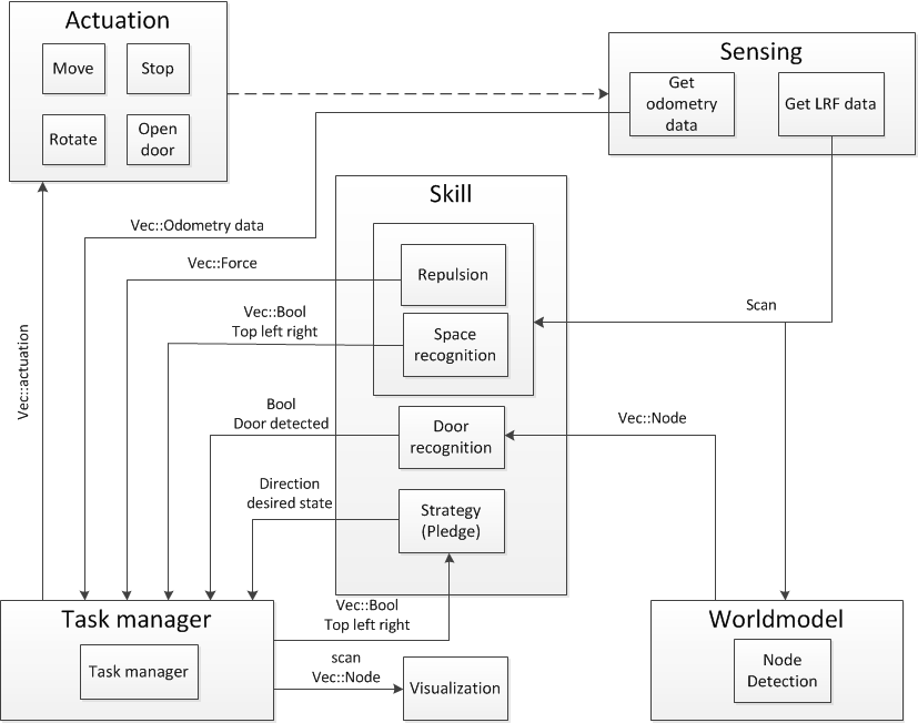
After the corridor challenge, the software architecture is changed a bit. The different software parts with their corresponding in- and outputs are depicted in Figure 2.
=== Maze solving algorithm ===
The Pledge algorithm is chosen to solve te maze. The pledge algorithm has a preferred direction and counts the corners the robot takes. A corner left counts as -1 and a corner right as +1. When the counter is 0, the robot goes in its preferred direction. The pledge algorithm is implemented in the following manner:
- If Pico is driving in preferred direction:
- if space_top = true: Go straight in preferred direction
- if space_top = false & space_left = true: rotate 90 degrees left
- if space top = false & spacel_left = false & space_right = false: rotate 180 degrees left
- Else
- if space_right = true: rotate 90 degrees right
- if space right = false & space top = true: go straight
- if space_right = false & space_top = false & space_left = true: rotate 90 degrees left
- if space_right = false & space_top = false & space_left = false: rotate 180 degrees left
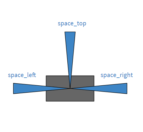
In Figure 3 Pico is depicted with three beams: space_left, space_right and space_top. All beams are using the 10 degrees of lrf-data.
Repulsion & wall following
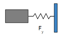
How the repulsion and angle correction are working is already explained in the section Corridor challenge. The final repulsion and angle correction are not changed very much in the final design, only some values are tuned. The wall follower is added in the final design, which makes sure Pico stays at a desired distance from the wall. The wall follower is implemented as a virtual spring. When Pico is too close to the wall, the repulsion becomes very high and Pico will be pushed from the wall. When Pico is too far from the wall, the virtual spring will give a force. Therefore, Pico will be pulled to the wall. Between the repulsion and virtual spring is some threshold, such that the forces are zero in that area. This makes sure that Pico does not correct itself the whole time.
World model
In order to recognize door areas a world model is constructed which uses landmark detection. Landmarks are defined as nodes, which are points in the LRF-data with certain properties.
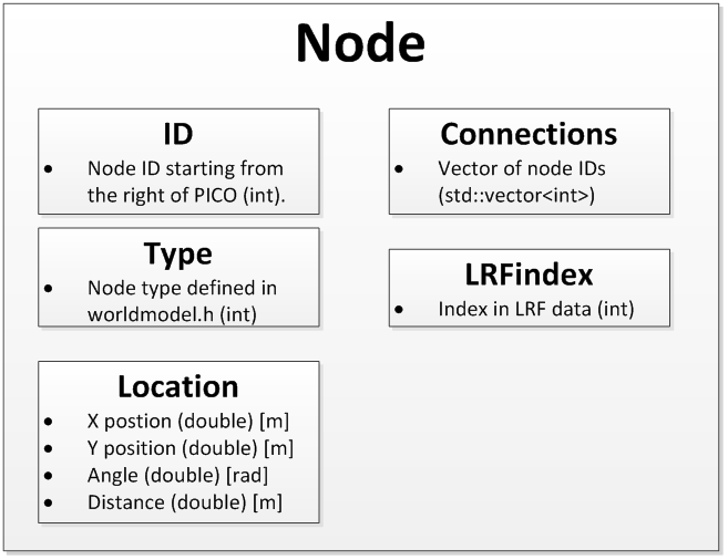
The Node class (data type) is defined as follows:
- ID (int): The ID of the nodes are set from right to left (in the scanning direction of the LRF) starting at ID 0.
- Type (int): The types are defined in the header file of the world model library worldmodel.h. Two types are currently in use: Corner nodes and End nodes.
- Location (location): For each node the Location class is used to track the position in both carthesian and radial coordinates relative to PICO. When the location class is updated using the radial coordinates the carthesian coordinates are updated automatically. VOEG FIGUUR TOE ASSENSTELSELS
- Connections (std::vector<int>): A vector of node IDs. For each connected node the ID is stored in this vector. Thus it is possible to determine which nodes are connected by walls and which are not using the Node class.
- LRFindex (int): Index in the LRF scan of the particular data point corresponding to the current node. It is mainly used to determine the connection vector.
FIGUUR NODE CLASS?
The world model is based on two types of nodes; endnodes and cornernodes. Finding nodes is done with the following checks over all data-points:
- The current data-point is a cornernode if the distance between the current data-point and the next data-point is larger than a given value.
- The current data-point is a cornernode if is passes the 90-degrees-test. This is a test that considers a previous data-point that lies at a set distance from the current data-point, and a next data-point that also lies at a set distance from the current data-point. Using the cosine rule, angles and distances to the three points, the actual distance between the previous and next datapoint can be compared to the distance between these points when applying Pythagoras. Pythagoras only holds if the angle is 90 degrees, so if the two values are equal, then Pythagoras is applicable and thus the corner is 90 degrees.
- The current data-point is an endnode if the distance between the current data-point and the next data-point is smaller than a given value.
- A data-point that lies at the maximum range or at the maximum angles is considered an endnode.
The visualization of the corner nodes and the end nodes serves to debug and tune the object recognition.

Several tunable parameters are associated with the node recognition: