Lego Mindstorms Robots
First Basic Model
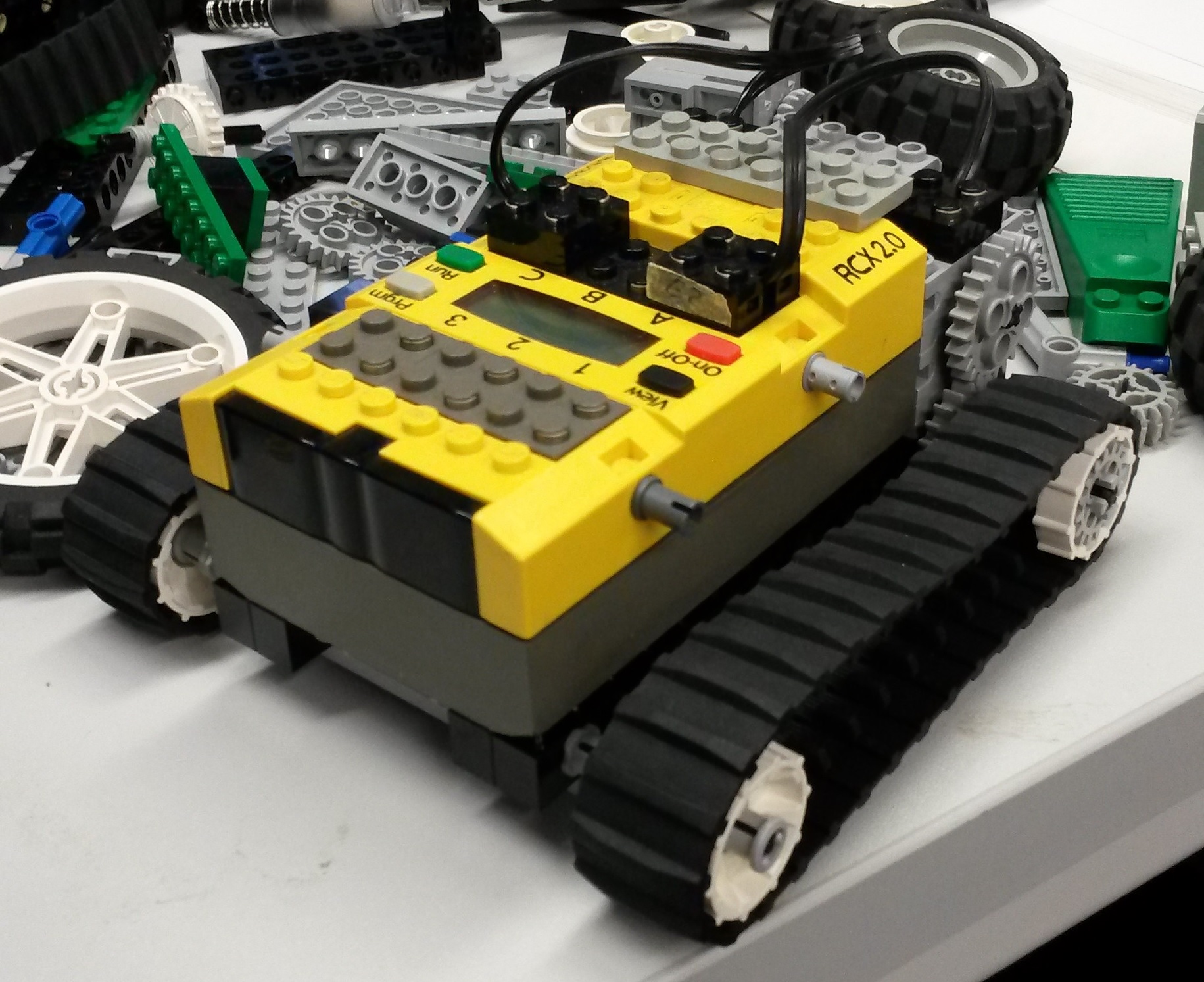
Before beginning to use the robots as a swarm a base model had to be created. After some time we came up with a simple but effective design, this model is shown in the following picture:
As can be seen it uses track tyres and two seperate motors to make sure the robot can move forward, backward and turn. This system was chosen as our design was focussed on simplicity and this model negates the need of a steering system or a swivelling wheel.
After building these basic units we needed to find out what extensions were possible, after some digging in the several boxes of lego bits we found the following actuators/sensors:
- Motor (actuator)
- Infrared distance (sensor)
- Axial Pulse Counter (sensor)
- Pressure sensor (sensor)
- light sensor (sensor)
Ofcourse in the swarm idea communication is a must, this will be further discussed in communication.
Final Basic Model
In Week 5, we came to the conclusion that working with the new NXT Brick of lego mindstorms would be much better than working with the older RCX 2.0 model. Primarely, because the [NXT Brick]] has bluetooth communication, while the RCX 2.0 only has IR communication. Together with the new NXT Bricks we obtained the associated lego as well. This, together with the fact that it was difficult to attach the new bricks to the earlier discussed basic model, made us decide to build a new basic model. The new model is shown in the picture below.
Programming
Programming of the RCX 2.0 brick used on the robots can be done in several ways. However the communication of a pc with the brick has to be done using a provided InfraRed Lego Tower. As drivers for this tower are only available for 32 bit-windows versions first a windows emulator needed to be found. After this communication with the brick was possible. Using the software and firmware provided on http://www.robotc.net/download/rcx/ called RobotC and after some fiddling with the drivers and the RCX 2.0 Controller the first program was created.
Communication
The NXT Brick, which is a newer version than the RCX 2.0, is able to communicate using cable or bluetooth. With the standard RCX 2.0 Bricks, bluetooth communication is possible.
An infrared interface is built-in in the RCX 2.0, which means that the robots can communicate using infrared. Problems with using infrared is that the communication only works over short distance, the robots should be somewhat pointed at each other and while a robot is sending infrared signals, it can not receive infrared signals and vice versa.
Therefor we found possibilities to have wireless communication between the robots on Wireless Communication with RCX, using different methods than infrared.
Methods that are described are:
- Analog Radio: using one of the variety of analog transmission systems, while building a specialized circuitry to translate the digital signals to analog and vice versa. This type of transmission (in addition to difficulties with translating the signal) suffers from noise. The user would have to implement his own handshaking and error-correcting protocols to achieve a reliable communication.
- Radio modem: using one of the available radio modems that translate the serial port communication to radio signal and back. An example of such a module would be Parallax 433 MHz RF Transceiver Package, which is a high-cost solution requiring two separate modules on both sides, and allows connecting for only a single pair of communicating devices. In addition, it is vulnerable to the interference with other devices that use the same frequences.
- Wifi: wireless Ethernet, (IEEE 802.11*) devices connect either peer-to-peer, or using a shared access point. An example of a robotic platform using WIFI communication were SONY Aibo robots. The advantages are the standardized and well-supported communication protocol, possibility for multiple units coexisting in the same space, while all the communication conflicts are handled by the lower levels of the communication protocols, transparent to the user. Another advantage is the possibility to connect the local WIFI network to the Internet, and thus expose the robots directly on the public network. Finally, WIFI networks have high throughput and can be used even in such applications as video transmission.
- Bluetooth communication protocol: This provides somewhat lower-cost alternative while keeping most of the advantages of WIFI: standardized protocol with automatic prevention of collisions and error correction, multiple communicating peers, secure authentication if needed. The communication speed is typically lower, but there is an advantage of performing as a direct serial communication link once a connection between the two communicating peers is established, and virtual serial port opened. Bluetooth platform is typical for many embedded devices, which can perform in slave-mode and can be connected by master (for example a PC). In that way, the PC can take the role of a hub and connects to multiple hosts at the same time, possibly coordinating the communication. An example of a Bluetooth modem device designed for embedded devices is the SparkFun BlueSmiRF module, which is a good option for our project to use.
The Tx and Rx pins of the BlueSmiRF module could be connected to the RCX's motor and sensor ports, but the RCX also has a serial port, so to save the motor and sensor ports, it would be best to utilize the serial port for the communication purpose. However, this will require some work since the serial port of the RCX is connected to the IR tranciever device. It would require us to built a circuit that transforms the data received from the BlueSmiRF into IR signal transmitted further to the RCX IR serial port. At the same time the device should transform the IR signal emited by the RCX's serial port into a TTL level input further into the BlueSmiRF module, which transmits it further over the Bluetooth radio protocol.
Such a circuit is shown in the figure below. Found on robotika.sk
Back to: PRE2015_2_Groep1


