Embedded Motion Control 2015 Group 6
Group Members
| Name: | Student id: | E-mail: |
| Akash Agarwal | 0923269 | a.agarwal@student.tue.nl |
| Angus Pere | 0926353 | a.f.pere@student.tue.nl |
| Ashish Yadav | 0925559 | a.yadav@student.tue.nl |
| Floris Remmen | 0920072 | f.remmen@student.tue.nl |
| S. Cagil Mayda | 0926975 | s.c.mayda@student.tue.nl |
| Ugonna Mbaekube | 0927006 | u.o.mbaekube@student.tue.nl |
| René van de Molengraft | Tutor | m.j.g.v.d.molengraft@tue.nl |
Planning
Week 1: 22 April - 29 April
- Introduction lecture
- Meeting 1: Initial design document & C++ tutorials
- Ubuntu and other required softwares Installation
Week 2: 29 April - 6 May
- 27-04 12:00: Deadline initial design
- Finishing C++ tutorials
- Start studyin maze algorithms
- Meeting 2: Division of team roles in the project
- Reading tutorials
- Prepare presentation
Week 3: 4 May - 10 May
- 6 May: First presentation of the design
Week 4: 11 May - 17 May
- 13 May: Corridor competition
Week 5: 18 May - 24 May
- Lecture 3: Composition Pattern part II by Herman Bruyninckx
Week 6: 25 May - 31 May
- 27 May: Second presentation of the design
Week 7: 1 June - 7 June
- Lecture 4: Communication patterns
Week 8: 8 June - 14 June
- 10 June: Presentation of final design
Week 9: 15 June - 21 June
- 17 June: Final competition
Update Log
Initial Design
Goal
The goal of the “A-Maze-ing challenge” is to design and implement a software for the PICO robot to navigate through a maze autonomously while optimizing time.
Requirements
To program a PICO robot to participate in the “A-Maze-ing challenge”, it is desired that the software meets the following requirements.
- The PICO robot should be able to navigate through any maze autonomously regardless of its configuration. (Autonomous Behaviour)
- The PICO robot should be able to avoid all obstacles during its navigation through the maze including contact with the walls of the maze.(Collision Avoidance)
- The PICO robot should never get “stuck” at any position in the maze and should make desired movements.(Movement)
- The PICO robot should be able to make use of its sensors to navigate the maze.(Use of Sensors)
- The PICO robot should have some sort of “memory” that prevents it from moving back towards paths already navigated through.(Awareness of the environment)
- The PICO robot should be able to find the optimal path through the maze while optimizing time.(Optimal Path Calculation)
- After navigating through the maze, the PICO robot should be able to autonomously terminate its movement.(Termination)
Functions
The basic functionality of the robot that are assigned to requirements in order to reach the goal are as follows:
1) Drive
- Move Forward
- Move Backwards (Reverse)
2) Obstacle & Wall Detection
- Calculation of Distance to objects
3) Decision Making
- Turn Left/Turn Right
- Rotate
- Termination of movement on completion of the maze
4) Optimal Path Algorithm
- “Memory” storage
- Localisation
Components and Specificications
Initial Schematic overview of the components to be used in the software design
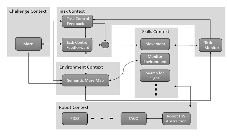
1) Task Context: Controls the implementation of the robots functions depending on the challenge and environmental context.
- Task Monitor: Monitors the implementation of the robots functions and sends the information to the task control feedback.
- Task Control Feedback: Implements control action on the robot based on information received from the task monitor.
- Task Control Feedforward: Contributes in the implementation of control actions on the robot depending on the state and the goal of the challenge.
2) Environmental Context: Semantic maze model.
3) Challenge Context: All information regarding the rules and the goals of the “A-Maze-ing challenge” are stored in this context.
4) Robot Context: This incorporates the low level specifications of the PICO robot.
5) Skills Context: Contains the above mentioned robot functionalities.
Interfaces
1) Challenge Context – Environmental Context: deals with presumptions about the maze and goal methodology.
2) Skill Context- Robot Context: deals with sending commands to the low-level hardware.
3) Task Context- Environmental Context: provides information to the task context about decisions to be made in the maze.
4) Challenge Context- Task Context: provides the aim of the challenge context to the task context in order for the task context to adhere to the rules of the game while decision making.
5) Task Context – Skill Context: Allocates the necessary skill dependent on the contribution of the task control feedforward and feedback.
Corridor Competition
For this competition, it was aimed to exit the corridor succesfully with an easy approach.
Hardware Components
- Wheels: the robot doesnt move in a straight line when a move command is given in the x direction. This is because of the omniwheels which make the robot rotate whenever it moves forward. For this reason we need an allignment algorithm.
- Laser Data: * The laser stores position information and angular information in laser data framework
* Every laser needs to be calibrated and multiple lasers are used to get a homogenous result and trustable data.
- Odometry Data: Gives information about the relative changes in X, Y and angular position. The first navigation algorithm was based on this odometry data, but since good results were not obtained, it was changed by using laserdata.
Initial Software Design
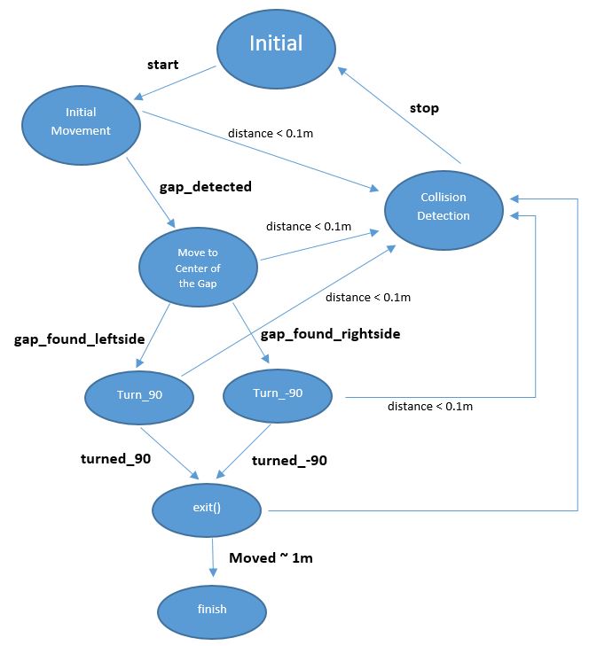
- Initial Movement: Robot starts with a constant speed and move forward through the corridor.
- Collision Detection: With using the laser data, distance to the wall or any other obstacles (no obstacles in this case) can be determined. If the distance becomes less than 0.1 metre, robot will stop to avoid collision.
- Position Alignment: It is observed that, due to feature of omni wheels, robot sometimes can not go straight. So in the algorithm, Pico is forced to stay in the middle of the corridor by calculating the distance to the right and left wall by using laser data.
- CheckCorridor: Robot will constantly check the distances to the left and right wall. If the distance to one of them exceeds the threshold (max.width has already known) turn left/right command will be executed.
- Turn Left/Right: After robot moves in the middle of the gap, it turns +/-90 degrees by using the odometry data. When it is turned, it again starts moving forward.
- Finish: Since the distance to finish can be approximated, after moving some distance, robot will stop automatically.
States of the initial design can be seen in the following figure:
Features of the Software
Collision Detection
When the distance between the robot and wall becomes smaller than 0.1 meters, initial collision detection function stop the robot before it hits the wall. This function will be upgraded further.
Position Alignment
Pico looks at its environment and takes the information from the laserdata to calculate the distance to the walls. If the difference in distance to both left and right side of the wall is the minimum possible, then a perpendicular relation is found. This also means that pico is going in a straight line through the centre of the hallway.
Find the Gap
While moving forward the above condition is checked at every time step, correcting itself where necessary. When pico encounters a turn, one of the distance vectors will increase drastically. At that point, pico stops and looks at its environment. It calculates (in the direction of the increased vector) the shortest possible distance to the wall and saves this point as the rotation point. The other side of the gap is calculated by using the same technique, but in a different quadrant. The rotation radius is then the half of the distance between these two points. After the rotation is complete pico starts from the beginning again.
Tests before competition
Updates to Software
Analysis of the Competition
Maze Competition
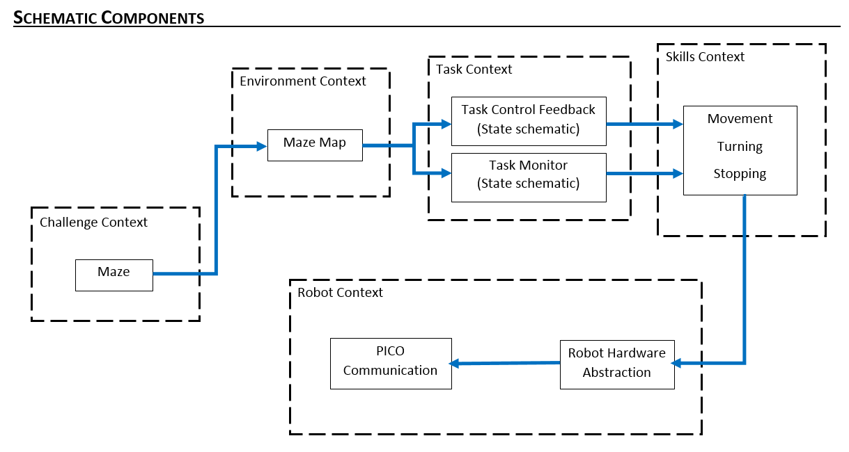
Components and Specificications
Initial Schematic overview of the components to be used in the software design
Interfaces
1) Environmental Context - Task Context:
The task context identifies the geometric shape at the junction, and then places a node and saves the node's orientation, parents, and children. The information regarding the node is then passed back to the environmental context which then updates the the local map. Based on the type of junction encountered, the task monitor then sends this information to the skills context
2) Task Context - Skills Context:
The skills context then implements the particular robotic skill needed to traverse the geometric shape encountered. After the required skill is implemented, the information is sent back to the task context which then updates the task monitor. The task monitor then sends the information to the environmental context which updates the position of the robot in the maze.
3) Skills Context - Robot Context:
Dependent on the skills to be implemented, the code is sent to the low level robot context which then implements the particular behaviour wanted and passes the information back to the skills context
4) Finite State Machine:
In order to navigate within the maze, a finite state machine (FSM) was implemented. The purpose of the FSM was to assign the right state which is dependent on the occurence of an event or multiple events. Below is the state diagram showing the transition between states.
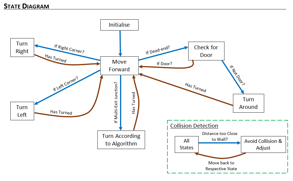
From the diagram, it can be seen which respective event triggers a state.
The events are
- if right corner detected
- if deadend detected
- if door present
- if door absent
- has turned around
- if right corner present
- if left corner present
- has turned
- if multiple exit junction detected
Building our local Map
In this assignment, we thought about building a world map using the hector mapping library but encountered several issues with the importing. on further thought we decided to use a local map which will be built as we navigate through the maze. At the starting position of the maze we place a node with index 1 and store its orientation. On moving, when a junction (junction here meaning a geometric shape which would require the robot to change state) is encountered, another node is placed there storing its orientation, parent and children. Depending on the type of junction encountered, the second node will check the left, right and forward extreme of the junction and then store these positions as its children in the map. This process is continued till the entire map has been stored.
Algorithm
The algorithm we have adopted is a subset of the depth first search algorithm with the nodes placed at respective junctions. Each node comprises of a parent and several children.The children of the nodes are at the left and right extremes of the junction. When the robot moves down a desired path and encounters a dead end, the robot is then able to backtrack to the previous junction by moving to its parent. When a node is visited, this information is stored and used when searching for unexplored areas. This technique is not optimal as it focusses on navigating through the entire maze rather than searching for the optimal distance but it is more reliable as it makes sure it explores the entire span of the maze. Also anytime a node is visited, the index of the node is stored in the visited section thus enabling us to know when a node has been visited and thus enabling us to navigate through the maze without entering an infinite loop.
Code Interaction
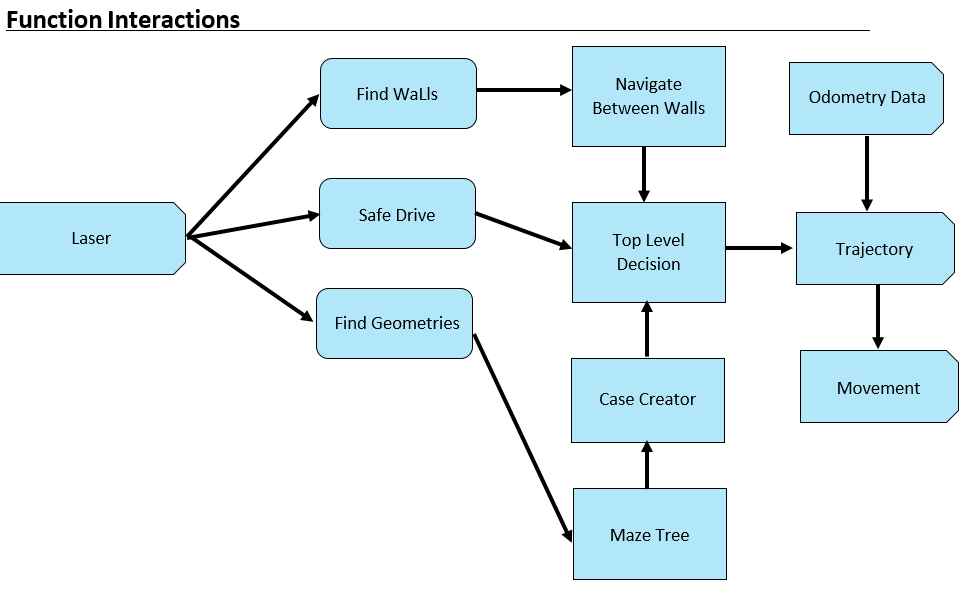
The main program uses some defined robot functionalities in order to achieve its goal. Below, interaction of all functions and global ros input variables can be seen.
Find Geometries
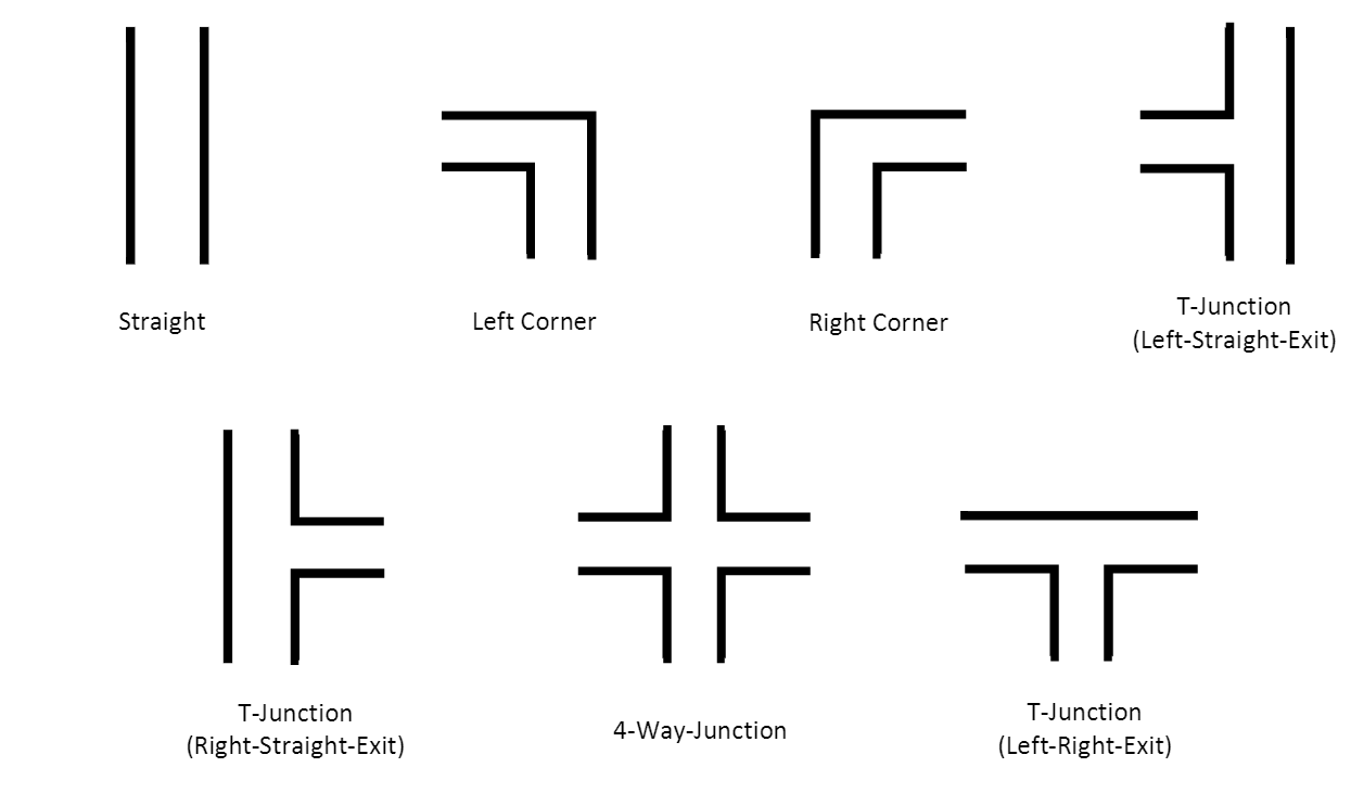
The robot should be able to recognize all possible geometries in order to navigate through the maze. State changes will be determined by detected geometries while the robot is moving. Defined geometries are shown belown:
Main Algorithm:
- Start scanning the environment from -90 to 90 degrees with respect to the robot. Pico's view is seperated as left, middle and right. Middle view is responsible for measuring the distance in front of Pico. Therefore this distance is calculated by using range of points inside the middle view in order to get more reliable result. Left and right views are responsible for the detection of edges in front of the Pico.
Movement
Finish Condition
Observations and Recommendations
Time Survey Table 4K450
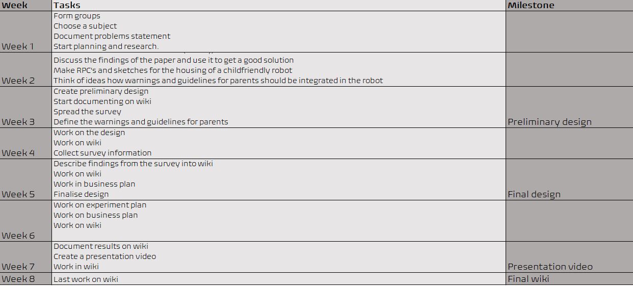
Total Score(Based on total working hours):
- Ugo : 10
- Cagil : 9.7757
- Akash : 9.6412
- Angus : 9.4394
- Floris: 9.4394
- Ashish: 9.3273