Mobile Robot Control 2020 Group 10
Team members:
Arend-Jan van Noorden (1378147)
Sjors Boutkan (0938234)
Jeroen van Meurs (0946114)
Koen van Gorkom (0954964)
Friso Buurman (0906665)
Escape Room
Design Document
The design document of group 10 can be found here.
Strategy
Solving the escape room is quite simple: find the corridor and drive through it. This document givesan overview of the system being build to solve this task.Finding the corridor is done by detecting the two outside corners marking the start of the corridor.Since the room is square, no other outside corners will be present in the environment. If these cornerscan’t be found from PICO’s initial location, it’ll follow the walls of the rooms clockwise, until thecorridor (outside corners) are encountered. The corresponding state diagram is shown in Figure1.1. The movement and navigation will be done using set-points and a potential-field algorithmpreventing PICO from hitting any obstacles or walls.
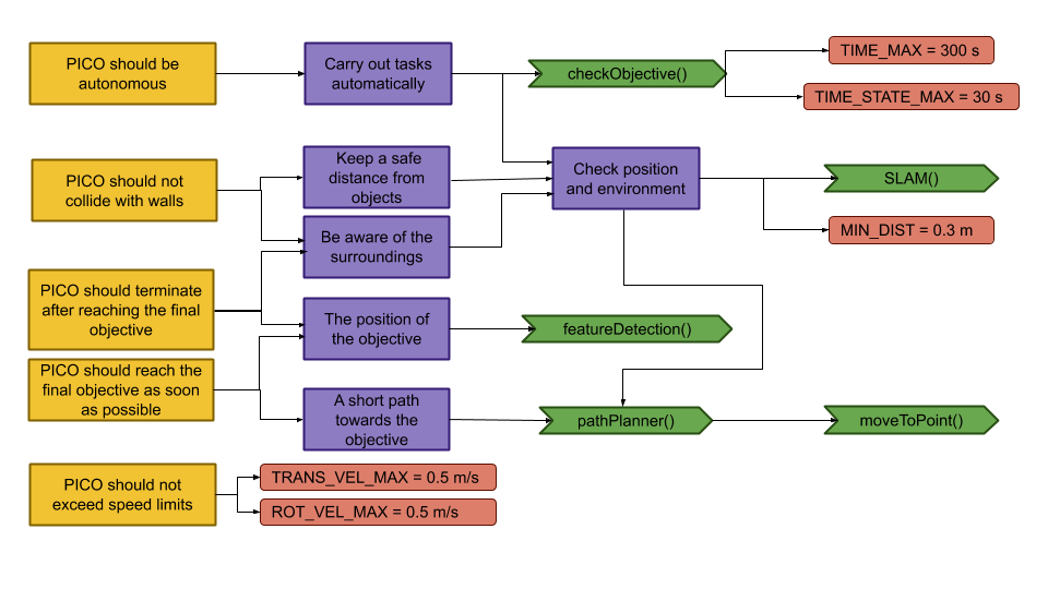
Requirements and Specifications

| Requirements | Specifications |
|---|---|
| PICO should not bump into walls | PICO's measurements are 0.41 m in width by 0.35 m in length |
| The free radius around PICO should be at least 0.21 m | |
| PICO cannot exceed speed limits | Maximum translational velocity is 0.5 m/s |
| Maximum rotational velocity is 1.2 rad/s | |
| Since PICO will be autonomous, it should be aware of its surroundings. | PICO should have an accurate map of its surroundings. |
| LRF range is between 0.01 m and 10 m. | |
| LRF FOV is from -2 to 2 rad, measured over 1000 points of equal increments. | |
| PICO should terminate when the final objective is reached. | PICO should come to a stop after it has crossed the finish line. |
| PICO should reach the final objective as soon as possible. | PICO should cross the finish line within 5 minutes. |
| PICO should not end up in a live lock state. | PICO should not keep repeating one action for over 30 seconds. |
| PICO should not end up in a dead lock state. | Careful coding has to be done to have no dead lock states. |
Components and Functions
Basic architecture of robot code:

All functions need to be run based on a Finite State Machine. As with sensors, all data has noise so these data streams need to be filtered.
The tasks of each component can be divided in several functions each with a specific subroutine.
World model
The world model stores the information gathered by the components and distributes this information to the other components. The information consists of:
- A map of the surrounding area.
- A list of found features.
- The current and previous state.
- The next position to travel to.
The world model contains no functions because the world model is only used to store the world data, so there are no active subroutines present.
Plan
The plan component uses data from the world model to determine the next position PICO needs to go to. It thereby also check if the objective is met.
- checkObjective()
The checkObjective function is the supervisor of the complete system. It controls/executes the states as defined in figure \ref{fig:state-machine} and executes the strategy as described in \ref{sec:strategy}. It will also check for failure of the system by identifying incorrect states, e.g. not moving for a set amount of time, following a wall for too long or having made a complete loop of the room without finding the corridor.
- pathPlanner()
The plan component contains the path-planner function, this functions is responsible to define the setpoints for PICO. These setpoints will be determined based on the state machine and the world model.
Control
The control component makes sure PICO moves along the planned path.
- moveToPoint()
The move to point function will be used to move PICO to the set point generated by the path planner. To prevent that PICO will hit the wall, the world model will be used to determine the trajectory from the current position of PICO to the set point.
Monitoring
The monitor component will try to identify features from the world model data.
- featureDetection()
To determine the corners and walls of the maze the feature detection function will be used based on the world model data.
Perception
The perception component will gather the sensor data, clean it and update the world model with it.
- getLaserData()
To acquire the data points of the laser sensor, the get laser data function will be used. The gathered data will be preprocessed to filter out the disturbances. The processed data will be written to the world model.
- getOdomData()
The odometry date will be read out with the getOdomData function. This date will be written to the world model.
- SLAM()
The gathered data from the laser and odometry sensors will be used to generate a map of the environment using Simultaneous Localization and Mapping (SLAM)
- UpdateVisuals()
A window will be opened that shows all the detected features and the path that PICO is going. This function will update that window
Interfaces
All components interface with the world model, getting data required for their functions and setting data created to be used by other components. The world mode is the central data store. This can also be seen in figure Figure Boven. Differences between the the proposed system and the system originally shown in [1], is that there are no interfaces between the 'resources' and 'capabilities' and the world model. The world model will not be able to get it's own data or control the motors of the system. The interface to the sensors will be through the perception component and the controlling of capabilities will be done by the control component.
Challenge result
Sadly we did not manage to get out of the escape room, below we will discuss why and how we solved it.
Main
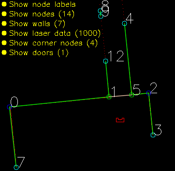
The main program for the maze challenge is using the state machine as shown in the Components and functions paragraph. In the first state the robot will turn to check if it can see a door or a outside corner. A door is defined if there are two outside corners within 0,5 m and 1,5 m from each other, or a outside corner and a wall within the same range as with the outside corners.

Backup
With the backup attempt Pico said it was finished directly after meeting the first wall. The reason this happened is that the first state after reaching the first wall is rotating 90 degrees to the right. When Pico did that the the surrounding wall distance was too large so the script thought all directions were free. To solve this the rotating right state has been changed from a hard rotate to a soft rotate until conditions are met. This made Pico align to the wall, and thus finish the map.