Embedded Motion Control 2014 Group 5
Group 5
| Name | Student | |
| Paul Blatter | 0825425 | p dot blatter at student dot tue dot nl |
| Kevin van Doremalen | 0797642 | k dot p dot j dot v dot doremalen at student dot tue dot nl |
| Robin Franssen | 0760374 | r dot h dot m dot franssen at student dot tue dot nl |
| Geert van Kollenburg | 0825558 | g dot o dot m dot v dot kollenburg at student dot tue dot nl |
| Niek Wolma | 0633710 | n dot a dot wolma at student dot tue dot nl |
Planning
Week 1
- Instal Ubuntu
- Instal ROS
- Setup SVN
- Tutorials
Week 2
- Continu tutorials
- Setting up program for first test
Week 3
- Finishing tutorials
- Continu on program first test
- First test robot
- Program architecture:
File:Nodeoverview.pdf
Week 4
- Everyone has finished the tutorials
- Working on program for the robot (we started too complex and therefore we have to build a more simple program for the corridor challenge)
- Setting up program for corridor challenge
- Second test robot (unfortunately, we didn't manage to test with the robot)
- Corridor challenge (PICO did the job with our program, which wasn't tested before! More information about the program can be found below.)
Week 5
- Meeting with tutor on Tuesday May 19th
The following subjects will be discussed during the meeting:
- Evaluation corridor challenge
- Setting up a clear program structure (group)
- Implementation of odometry data (1 person)
- ROS structure (1 person)
- Improvement of program for corridor challenge for implementation in final challenge (1 person)
- Path planning (1 person)
- Detection of arrows with camera (1 person)
- Finishing wiki corridor competition (1 person -> several hours)
Week 6
Week 7
Week 8
Week 9
- Maze challenge
Introduction
The goal of this course is to implement (embedded) software design (with C++ and ROS) to let a humanoid robot navigate autonomously. The humanoid robot PICO is programmed to find its way through a maze, without user intervention. On this wiki page the approach, program design choices and chosen strategies which are made by group 5 are presented and explained.
Corridor Challenge
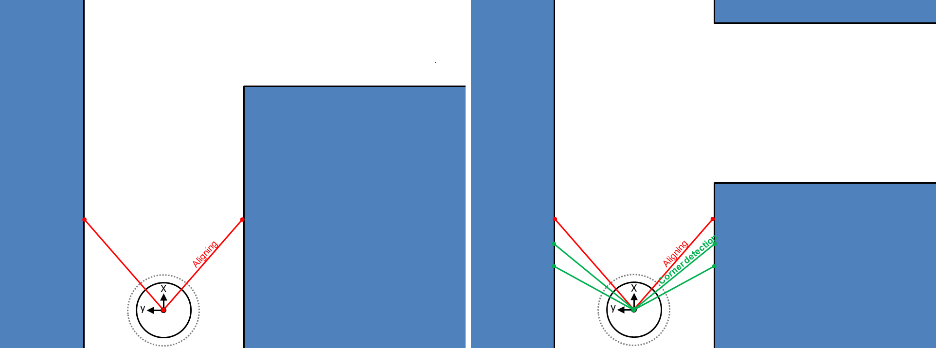
The corridor challenge was on Friday May 16th 2014. In the days before the corridor challenge the program was build and simulations were run with Gazebo. Due to some implementation errors and programming difficulties, the program wasn't tested in real on PICO before the challenge. However, with this program PICO managed to finish the corridor challenge! The strategy of the corridor challenge will be explained with the following pictures and further improvements will be considered.
First, an aligning function is added to the program. PICO has to drive through a corridor without hitting the wall. The aligning function compares the distance to the wall of the laser angle of -180 degree and +180 degree w.r.t. to the x-axis of PICO. When the difference between these distances becomes to large, the program sends a rotation velocity to PICO in a way that this difference will be decreased up to a certain threshold. With this aligning function PICO will be kept in the middle of the corridor. Second, the corner detection looks at two laser points at the left and two laser points at the right side. The laser points at each side have a different angle (difference around 2.5 degree).
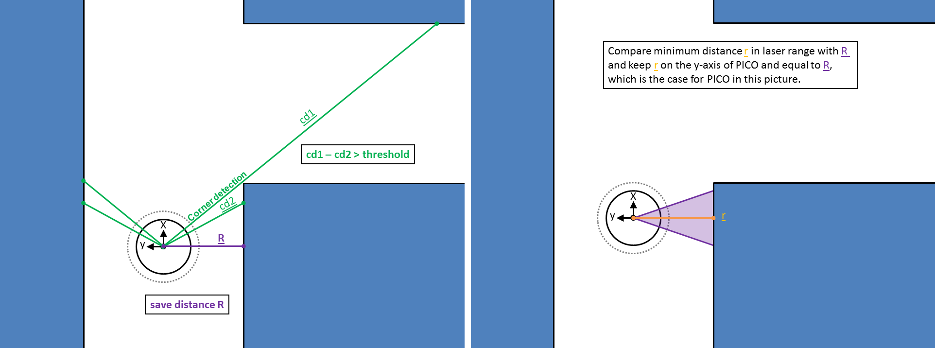
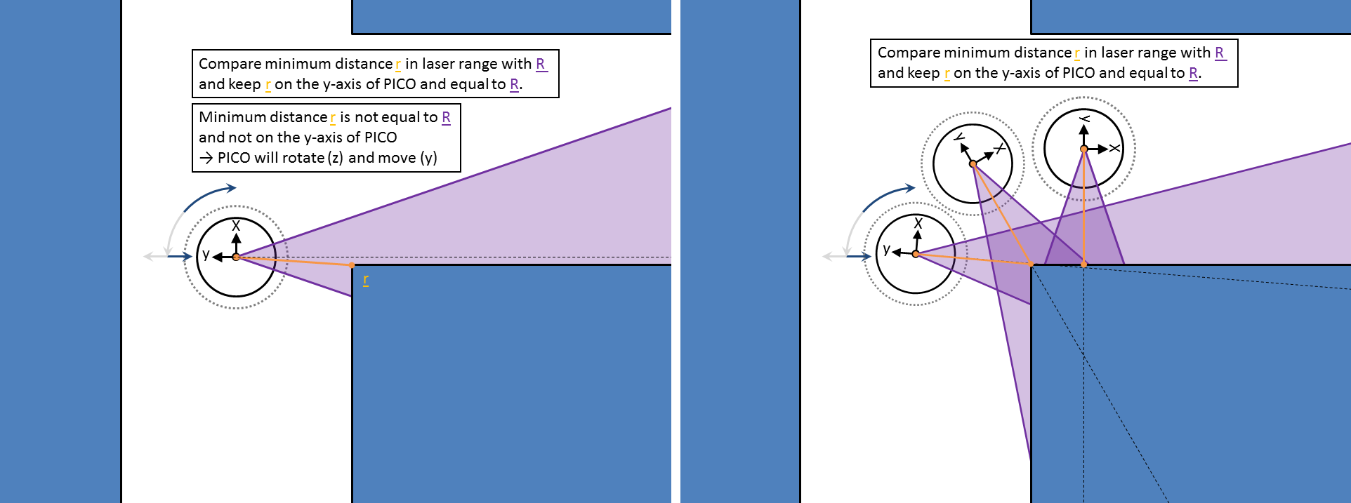
A corner is detected when the difference between the laser points at one side (right or left) is above a certain threshold (=1.0 meter). Then the aligning function and corner detection function stop and the program starts with the cornering function. The cornering function detects directly the smallest distance (R) on the y-axis of PICO with respect to the wall in the corridor. This distance will be maintained during cornering in a small laser range (this smallest distance doesn't have to be exact on the y-axis of PICO, but around this y-axis). The angular velocity and y-velocity are set in the program to keep this distance. And with the cornering function the explanation of the program for the corridor challenge is finalized.
Further improvements (to be extended):
- Implementation of odometry data which can solve the problem that PICO didn't correctly turn 90 degrees in a corner (corridor challenge).
- Use of laser range instead of some laser points.
- Calculation of thresholds and possibility of variable thresholds.
Program Architecture
Laser data
The robot contains a laser, which has a view of 270 degrees.
Odometry
Odometry is the use of data of the angular positions of the robot wheels. This data is used to estimate the position of the robot relative to a starting point. The angular positions are converted into Carthesian coordinates (x-, y- and theta-direction). This data is never fully accurate, inter alia due to wheel slip.


