PRE2018 4 Group9
Group members
| Member | ID number | Program | |
|---|---|---|---|
| Rob de Mooij | 1017797 | Biomedical Engineering | r.a.j.d.mooij@student.tue.nl |
| Ilja van Oort | 1001232 | Biomedical Engineering | i.v.oort@student.tue.nl |
| Sara Tjon | 1247050A | Applied Physics | s.c.c.tjon@student.tue.nl |
| Thomas Pilaet | 0999458 | Industrial Design | t.h.m.pilaet@student.tue.nl |
| Joris Zandbergen | 1231962 | Industrial Design | j.m.zandbergen@student.tue.nl |
Problem statement
The problem of space debris is becoming bigger and bigger. This debris is the consequence of decades of objects being launched into space and a lot of this debris causes a danger to other functional satellites. This debris consists of used rocket-stages, non-operational satellites and parts that were created through collisions and anti-satellite tests. Since the 70s this problem has been getting increased attention and big space associations like NASA and the ESA are constantly tracking this debris and preventing the creation of more. That is why most newly built satellites have built-in procedures that make sure the satellites de-orbit when they become out of order [1]. However, there has already been put a lot of material into orbit and since these objects can reach speeds of 8 km/s they can cause serious damage [2].
One would say that this would not be a big issue considering the vastness of space, however the opposite is true. The chance of a collision between a satellite and a piece of debris larger than 10 centimeters in low earth orbit was about twenty percent a year in 2007. This percentage rose to fifty percent just in 2009 [2]. This chance of impact creates a great risk for operational satellites and even more importantly for the International Space Station (ISS). The ISS is constantly assessing the risks of space debris hitting it and safety measures are already applied in order to decrease the chance of critical damage. Using radar and telescopes, debris down to 10 centimeters in diameter can be tracked and therefore also avoided by the ISS [1]. The ISS’s crucial parts are protected by a dual layer wall, called a Whipple shield, which shields them from debris with a diameter of smaller than 1 centimeter [3]. The biggest danger for the ISS is therefore space debris with a diameter approximately between 1 and 10 centimeter, for which the ISS currently cannot defend itself against. For simplicity, we will mainly refer to this type of debris as ‘small debris’. Although the risk of such a fatal collision is small, a single collision with this type of space debris could be catastrophic to the ISS and the crew inhabiting it. The astronauts on board the space station already have a stressful and high-risk function. Finding a solution for this problem is therefore of great importance. As long as space debris maintains its undeniable presence in LEO, no spacecraft is safe from the dangers it presents, especially considering the continuation of the International Space Station program until 2030 [4]. Therefore, action in the form of research and pilot-tests should be taken as soon as possible to ensure the safety of the ISS in relation to the particularly dangerous centimeter sized space debris.
Objectives
- Determine the problems’ stakeholders and their requirements
- Research and compare methods of active defense of the ISS from small debris.
- Analyze the available detection, tracking and remediation systems in their ability to actively protect ISS from small space debris objects.
- Implement a model which simulates the active protection of the ISS.
- Test and analyze the systems feasibility on the basis of the models’ results together with the stakeholders’ requirements.
Approach
In this report, different methodologies will be analyzed as to assess whether they are fit for the defense of the ISS. Next, the feasibility of the methodology that satisfies the requirements best will also be assessed. The legal and financial aspects of the proposed solution will be discussed. The technical feasibility of the defense system will be tested using a model in MATLAB. Firstly, the debris environment will be modelled by simplifying debris dynamics and considering a variety of conditions. The geometry of the ISS will be simplified and its structures will be categorized according to the magnitude of the threat posed by orbital debris in case of collision. The chosen defense system and its influence on the orbit of the debris will be characterized and implemented in the model. Incoming debris will be simulated both when the system is and is not implemented. The effectivity of the system can then be compared by analyzing these results. Parameters related to the defense system (that could also be varied in a realistic context) will be varied to determine the most effective way to employ the solution. Finally, a user scenario will be described, in which the proposed methodology is placed in a practical context.
USE Stakeholders
Below the stakeholders which are involved in (protecting) the ISS will be discussed. This will be done in the USE-format (User-Society-Enterprise). First of all, a summary of the corresponding stakeholders will be given. Then, they will be discussed in more detail.
User
- Passengers aboard the ISS: Normally there are six people aboard the ISS. Their main responsibility is to perform experiments and repair malfunctioning parts of the ISS [5].
- ISS Mission Control Centers: Responsible for the proper functioning of their own modules and have continuous communication with other control centers and the ISS itself [6].
Society
- Research institutions: Many research institutions from the federal and private sector have research located on the ISS. This research is focused on many different types of sectors [6].
Enterprise
- Partnered space associations: The five partnered space agencies closely work together in maintaining and building the ISS. All five also provide astronauts for the ISS crew [6].
User
There are two groups of users for this proposal. These are the astronauts and the ISS control centers. Currently, these two groups already work together in protecting the ISS. This specific collaboration is mostly focussed on protecting the ISS (and the astronauts) from space debris bigger than 10 centimeters. Debris of this size can be tracked with radars from the Earth’s surface. When a piece of debris is observed and it appears that its orbit will bring it close to the ISS, the astronauts will receive a warning from the control center (in Houston). Depending on the chance of collision the astronauts either receive a yellow or red alert from the ground. Whether the control center then performs avoidance maneuvers depends on the chance of collision and on the consequences of such maneuvers on mission objectives [7] [8].
As said all these avoidance maneuvers are performed by mission control and the astronauts do not have to perform or activate any of these maneuvers themselves from within the ISS. They are however aware of when these maneuvers are happening. This would be different in the scenario for our proposal. It is very likely that in our proposal a piece of debris from 1 to 10 centimeters could only be detected 10 seconds before it would (potentially) hit the ISS. In this timeframe nor the control center nor the astronauts would be able to react in time. Therefore our system would be made autonomous.
Society
The main advantage of the ISS is the platform it provides for research. Its size and passengers give research institutions the ability to perform research in zero gravity for a long-term period. The research conducted on the ISS is in fields such as astrobiology, astronomy and materials science. The experiments in the ISS can be accessed and modified by the astronauts on the station on request of scientists on Earth [9]. In conclusion, many research institutions on Earth have a stake in the experiments conducted on the ISS. The advances are not only important for institutions in the field of astronomy, but in many more as well [9]. This means the whole of humanity gets benefit from the results of the experiments on the ISS.
The research on the ISS is located in different areas of the ISS, mainly in allocated modules [10]. If one of these modules would get damaged, the (repair) costs would be large. The module would have to be replaced or repaired. Plus, the research inside the module could be lost or unusable. For this reason, among other things, research institutions (and the whole of humanity) benefit from (at least) the research modules being protected from space debris. Since the research modules are used by institutions from different countries it would only be fair if each module is equally protected, because one cannot objectively state that for example American research is more important than Japanese research.
Enterprise
Five different space agencies are part of the ISS program, namely NASA (United States), Roscosmos (Russia), JAXA (Japan), ESA (Europe), and CSA (Canada). The ownership and use of the space station is established by intergovernmental treaties and agreements. The station is divided into two sections, a Russian and an American section [6] [11]. All these space associations have put a lot of money in building the station [12]. Seeing it get damaged by space debris is thus very undesirable for them. Therefore it would be in their interest to protect the station through for example our system. As said in the 'Society' section above it would be desirable if the whole of the ISS, or at least the most vital parts, is equally protected and none of the space agencies is favoured by our system. Next to this it would also be desirable (if not required) if the system cannot be used maliciously. It should operate independently from interests from space agencies. The main goal should be to protect the ISS as a whole. However, the use and ownership of the modules/systems on the ISS is set out in already existing agreements, which will be further elaborated later on.
Requirements
- The method must be able to detect and track space debris of 1 to 10 centimeters autonomously.
- The method must be operable until at least 2030 [4].
- The method's costs must fit reasonably within the space associations budget.
- The method must be able to operate on the available energy stored in the ISS or the system’s own stored energy.
- The method must not increase the amount of space debris in orbit and therefore increase the chance of collision with satellites (and other pieces of debris) in orbit.
- The method's legislations must make sure the system cannot be misused for military purposes.
- The method must be operable at all times.
- The method must communicate its current status at all times to mission control centers to make sure malfunctions can be detected.
Active defense method
Debris Remediation
So far, concepts and developments concerning orbital debris have mainly considered suitable methods for the active removal of (large) debris, instead of the defense of spacecraft against small, immediately threatening debris. Therefore, in choosing an appropriate methodology of defending the ISS against this type of debris, we will consider methods originally conceived for active debris removal and determine how well these could adapt into a potential defense mechanism for the ISS.
A common way to classify techniques for the active removal of debris is whether or not it requires some form of contact between the device and debris [13]. In particular, techniques that make use of rigid contact (such as a robotic arm) do not seem to be well suited for defending against small debris. This type of remediation involves a stable connection between the device and debris, which is particularly problematic in the case of small, tumbling debris of varying shapes and sizes. Clearly, these techniques are way more fit to remove large space debris from orbit [14]. An exception to this is the employment of a capturing net. A useful property of this technique is its compatibility for different sizes of debris. Furthermore, targets can be captured from a larger distance (as, in contrast to other techniques requiring rigid contact, the device does not have to dock to the debris) and capture does not need to be as precisely controlled.
Alternatively, techniques that do not require such a stable connection between the device and debris may generally be more applicable to our case. An interesting example is drag augmentation: debris can effectively be removed from orbit by increasing the drag it experiences in its trajectory. Similar to the net capture method, debris of varying sizes can be remediated with this technique from a relatively large distance. One way to accomplish this (currently under development by the ESA [15]), uses foam that sticks to the debris surface, causing a significant increase in the area-to-mass ratio of the object (which, in turn, results in an increased drag).
In contrast to these techniques, some methods do not require any form of contact between the device and debris. These contactless techniques avoid many of the issues related to achieving a stable connection between a device and an orbital debris object. Moreover, these techniques can remediate debris from a much larger distance than any of the contact-based alternatives discussed. Important examples are a laser system, as well as ion beam technology.
Another important distinction to be made in deciding how the ISS can best be protected is the localization of the remediation system. The system can operate either on the ground or in space. In case of ground-based systems, contactless techniques are the only methods available. In particular, the employment of laser systems on ground for the active removal of debris has already been researched extensively [16]. An obvious advantage of ground-based laser is that they do not have to be sent into space, which makes it both economically and technically more attractive. Furthermore, reparations can be made much more easily to constructions on ground. However, the system must be able to track and alter the trajectory of the debris within a matter of seconds. In order to accomplish this, a precision and tracking velocity beyond our current capabilities is required. Therefore, these systems are simply not suitable for rapid remediation of threatening debris.
In conclusion, the system must be situated somewhere in space. This system could either be mounted on one or more satellites or on the ISS itself. In case the system is mounted on one or more satellites, these satellites must orbit close to the ISS to allow them to remediate incoming debris. In order to properly defend the station, a number of these satellites must be employed which can take care of debris coming from different directions. This would most likely be very expensive. Furthermore, changing the trajectory of the incredibly fast orbital debris objects requires a large amount of energy. If mounted on the ISS itself, the system can benefit from the energy supplied by the solar panels on the space station. Additionally, reparations could be performed by the crew aboard the ISS if the system would reside here.
Another reason why the best option would be to attach the remediation system to the ISS are the legal issues that arise when not attaching the system to the ISS. Currently, the legal framework of the ISS says that the agency that provides and develops a new ISS module is the agency that retains ownership of this module. In this legal framework there are more rules set out for agreements about malicious use, cooperation and so forth. Not attaching the system to the ISS will put the system outside of the ISS’ legal framework. This could lead to possible legal issues, because the system is not actually part of the ISS. To avoid such issues the system has to become an actual part of the ISS. Looking at the above factors, we conclude that the system should be mounted on the ISS itself.
It seems intuitive that such a system must make use of a contactless remediation technique. Any method based on contact would require a significantly smaller distance between the ISS and the debris, which simply would not leave enough time to deorbit the threatening debris. Now, there are two main types of space-based contactless debris removal: laser systems and ion beam systems. However, an ion beam system such as the Ion Beam Shepherd must retain a (constant) short distance between itself and the target, which would be highly impractical when mounted on the ISS [17].
In recent years, research has been done about the development of space-based laser systems [18][19]. These were mostly aimed at the active removal of space debris, without directly considering the immediate protection of the ISS. These laser systems are capable of ablating small debris in the Low Earth Orbit and can have a range greatly exceeding contact-dependent removal systems. Therefore, such space-based removal systems may also have the potential to actively defend the ISS. In conclusion, the inclusion of one or more laser systems on the ISS is the best way to actively defend it against small debris.
Concluding, the most viable solution for remediation system is attached to the ISS, but does not have rigid contact with the oncoming debris. A laser system could be a good option for this since it is easy to repair and easy to automate. The former can be done through EVAs (extravehicular activities) by the ISS crew. The latter is necessary since the response time for ablating the debris will most likely be just a few seconds. This is the case, because the current detection systems for localizing debris between one and ten centimeters only has a range of about one hundred kilometers. Elaboration on this detection system will follow below.
Detection
Detection of small threatening debris was proposed by Ebisuzaki et al. to be carried out by the EUSO-telescope, which was originally developed for the JEM-EUSO program and devoted to the detection of ultra-high energy cosmic rays. It has a field of view of about 30° and was calculated to be capable of detecting debris with a minimum size of 7.4 mm from 100 km distance. Therefore, it is particularly suitable for the detection of centimeter-sized debris. Detection can occur optimally in astronomical twilight, when the earth is in local night and the ISS and debris are still illuminated by the sun. In this way, orbital debris can be easily recognized against a dark background. This occurs during a time period of approximately 5 minutes during every orbit of 90 minutes. The system can also operate in daytime, although the increased amount of background photons may result in a larger amount of false positives. Therefore, it might be beneficial to pass the detection data to a list of the relative positions of operating satellites with respect to the ISS in order to prevent unintended targeting. In order to distinguish the unique pattern of the debris from the background, Ebisuzaki et al. suggest the employment of a linear track trigger algorithm to track the trajectory of orbital debris over a predefined time window. In daytime, this time window might have to be extended in order to ensure proper recognition of this debris. However, as the operation of the telescope depends on the detection of reflected sunlight, the system cannot function during nighttime. This is a significant limitation of the ablation system and should be addressed in future investigations on the subject. However, we will primarily consider the ability of the ablation system to track and deorbit threatening debris.
Legal issues for laser placement on ISS
ISS Legal Framework
The ISS is a joint project between several space associations of different countries and regions. These countries and regions are: Europe, the United States, Russia, Canada and Japan [6]. Each of these regions has their own laws and judicial rules. As to find a compromise between these different laws a legal framework especially for the ISS was set up. It defines “the rights and obligations of each of the countries and their jurisdiction and control with respect to their Space Station elements” [20].
Since this framework is quite a vast set of legal rules a selection was made on the rules that apply to this project. A summary of these rules can be found below:
- The International Space Station Intergovernmental Agreement (abbreviated to IGA): 'a long term international co-operative frame-work on the basis of genuine partnership, for the detailed design, development, operation, and utilisation of a permanently inhabited civil Space Station for peaceful purposes, in accordance with international law'
- National jurisdiction in outer space: The Intergovernmental Agreement allows the Space Station Partners States to extend their national jurisdiction in outer space, so the elements they provide (e.g. laboratories) are assimilated to the territories of the Partners States.
- The Space Station International Partners can barter or sell their unused utilisation rights among themselves and to other non-participants to the Station’s programme. The common philosophy of this approach is that goods and services are exchanged by space agencies without exchange of funds. The bartering system has enabled a significant reduction of technical and financial risks and has supported the process of standardisation and commonality in the Space Station Programme.
- ‘Cross-waiver of liability': prohibits any of the five Partners or their related entities to claim against another Partner for damage sustained as a result of ISS activities. Exceptions are, for instance, claims arising between a Partner and its own related entities. For example claims between the European Space Agency and one of its users, will be covered by contracts or subcontracts that will not implicate the other international Partners. Other exceptions to the cross-waiver of liability include claims for damages caused by wilful misconduct, claims made by a person for bodily injury or death, and intellectual property claims.
United Nations Committee on the Peaceful Uses of Outer Space
The mission of the Committee on the Peaceful Uses of Outer Space (COPUOS) is "to review the scope of international cooperation in peaceful uses of outer space, to devise programmes in this field to be undertaken under United Nations auspices, to encourage continued research and to disseminate information on outer space matters and to study legal problems arising from the exploration of outer space." [21]
Space treaties
During and after the Cold War several treaties were set up as to limit the chances of an arms race in space. As mutually assured destruction became the deterrent strategy between the two superpowers (USSR and USA) during that time, many countries worked together to avoid extending the threat of mass destruction weapons to space and space based launchers.
The first of these treaties was the ‘Outer Space Treaty’ [22] by the U.N., which was first signed by many of the world’s countries in 1967. The treaty banned the placing of weapons of mass destruction in space (including the orbit of Earth). Besides, it emphasized that the use of outer space should be carried out for the benefit and interest of all of mankind. Therefore the exploration and use of space should always be in a peaceful manner. One should note that this treaty does not ban the placement of weapons in space in general, only nuclear and other weapons of mass destruction.
Following the Outer Space Treaty another treaty was set up in 2006: the Space Preservation Treaty [23]. This treaty was a proposed UN General Assembly resolution against all space weapons. Only the US voted against. Again in 2008 a new draft was submitted by China and Russia. Again, the US opposed it, because they saw security concerns over its space assets even though the treaty explicitly affirmed the inherent right of self-defence for all states. Eventually in 2014 the General Assembly of the UN passed two resolutions on preventing an arms race in outer space. The first of these resolutions was called ‘Prevention of an arms race in outer space’. It “call[s] on all States, in particular those with major space capabilities, to contribute actively to the peaceful use of outer space, prevent an arms race there, and refrain from actions contrary to that objective.” 178 countries voted in favour to none against. Israel and the US abstained. The second of the resolutions was called ‘No first placement of weapons in outer space’. This emphasises the prevention of an arms race in space and states that "other measures could contribute to ensuring that weapons were not placed in outer space." 126 countries voted in favour to 4 against (the U.S. among others), with 46 abstentions (EU member states abstained on the resolution).
Influence on system proposal
The above named legal framework and U.N. space treaties have influence on the system proposed in this project. The ISS Partners (the five collaborating space agencies) will again have to reaffirm their promise to not make malicious use of the modules on the ISS, which the laser system will become a part of. If this promise is broken legal measures will and can be taken. Since all Partners have made this promise (and it is included in the ISS legal framework), there is no need to equally divide the costs of the system to all Partners. Instead, it is possible that one Partner (e.g. NASA) pays for the system and thus gains ownership of the system. Through the barter system that space agency gains favours from other agencies, since they now provided a system that also protects the modules and research that the other agencies provided. The size of these favours will depend on the amount of modules and research that each agency has provided in the ISS. The control of the system can also be in the hands of the agency that funded the system. Doing this would most likely increase the effectiveness of the system, since all of the control center operates smoothly, because the work culture is the same. It is necessary however that the space agency that is in control of the system gives updates of what the system is doing. The system remains a weapon and therefore it is likely that the other agencies will desire insight on what the system is doing. That the system could be seen as a weapon is and most likely will not become a problem. Currently, weapons such as this laser are allowed in space. The Space Preservation Treaty does call for the complete ban of weapons in space, but this treaty also says that the use of weapons in self-defense is still allowed. Since, this laser system would be created for the sole purpose of defending the ISS this system would also still be in accordance with this treaty.
Laser system
Energy available on the ISS
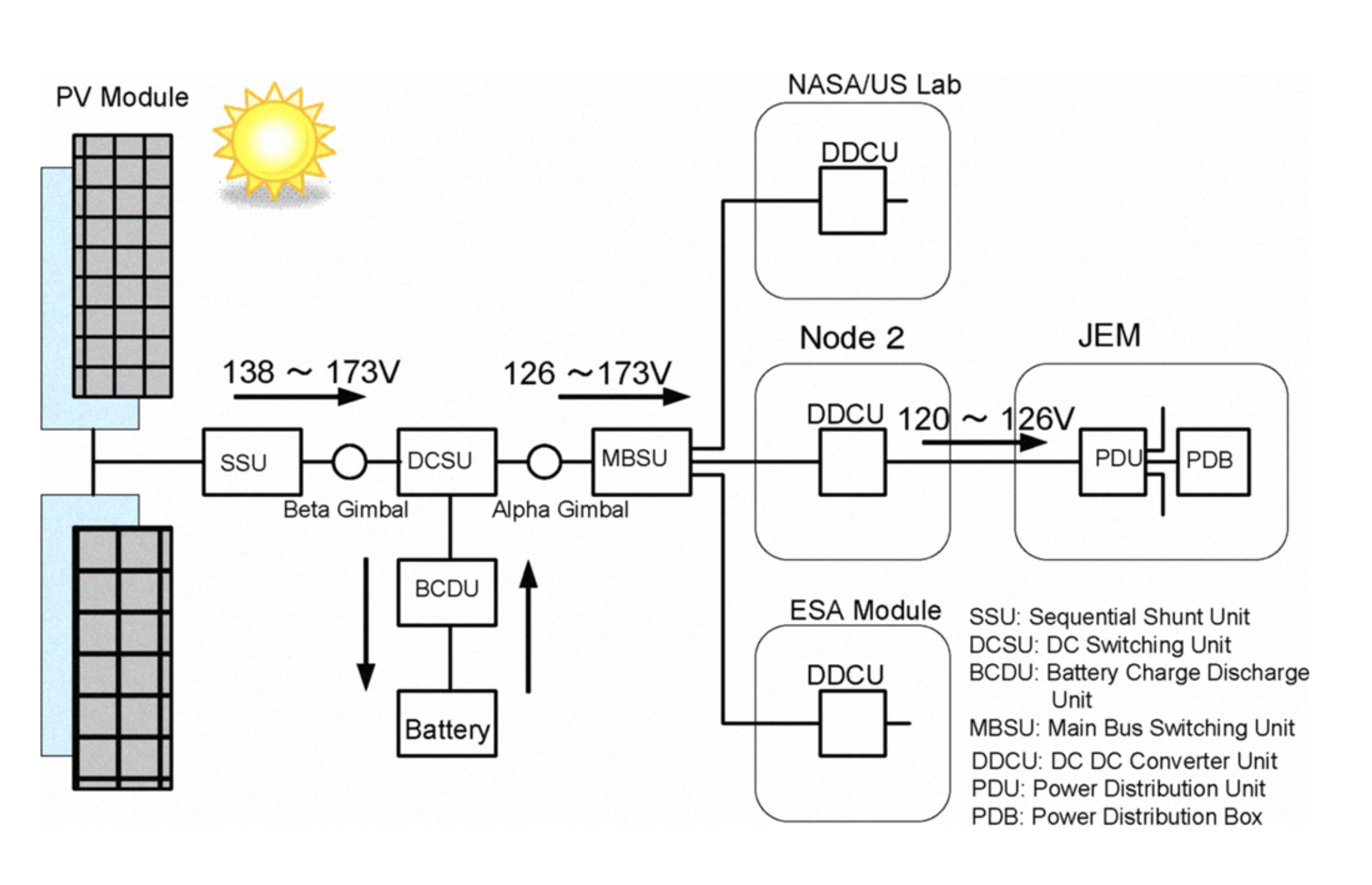
Photovoltaic panels acquire most of the energy needed on the ISS. Only for the periodic propulsion, the ISS uses fuel in the form of rocket propellant which is being refilled every now and then. The solar wings can generate up to 80 - 120 kW of electrical energy when the ISS is illuminated by the sun. At this point, 60% of that energy is being used to charge ISS’ batteries. These batteries are used for the “eclipse” part of the orbit of the ISS, because then the solar wings produce almost no energy. The output voltage of the solar arrays is about 138V DC. Firstly, the voltage from the solar array is roughly regulated by the SSU (see Figure 1), which makes sure the output voltage of the solar array does not have too much peaks or drops. Then the DCSU is used to switch between the input or output stages of the battery unit and the solar arrays. Subsequently, the MBSU does the switch regulating for the individual DDCU’s, which convert the 173V DC to 120V DC which then will be used as power through the whole of the ISS.
As previously mentioned, the battery is used to cover the ISS’ power usage when the solar array is not producing enough. The ISS has 24 Li-ion batteries together with 24 BCDU’s, which have a maximum output of 158.4 kW. Since the laser system would need to be operable at any time, even when the PV panels do not produce any electricity, it can only rely on the batteries maximum output of 158.4 kW. The laser would not have to draw, when firing the laser, power for a longer period of time than approximately 10 seconds. This means that the capacity of the batteries would not be the bottleneck. One option to increase the total amount of power the lasers can use is to add extra li-ion batteries to the laser modules.
Laser specifications
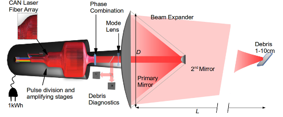
We will consider the specifications of the Coherent Amplification Network (CAN) laser, which is a novel fibre-based concept and was considered to be the laser system best fit for remediation of debris within the size range of 1 to 10 centimeters by Ebisuzaki et al. An intense beam can be produced by sending out a large sequence of laser pulses. For this specific purpose, one of the primary reasons for choosing this laser is its high electrical efficiency. In order to fend off the debris heading towards the ISS with high relative velocities (of more than 10 km/s), a fast response and high average power is essential for successful defense. The most important specifications of the CAN laser concept are described as follows [14]:
- The laser system is capable of ablating debris at a distance of approximately 100 km from the ISS. Therefore, if we consider the relative velocity of space debris, the system generally has less than 10 seconds to fend off incoming debris.
- The proposed laser system consists of 10.000 fibers. Since each fiber can provide 1 mJ of laser energy, the total energy in a pulse is 10 J.
- In case the laser operates at a high repetition rate (of 104 kHz), the laser can deliver average powers of about 100 kW.
- The laser can be aimed with a maximum angular velocity of approximately 0.1 rad/s.
- Using trains of pulses, the laser system can evaluate the surface condition of the debris, allowing for optimal interaction between the beam and the debris.
However, it should be noted that many of these specifications are conceptual in nature and have not yet been properly tested in practice. Since the system is still in development, further improvements could also be made in case the system proves to be insufficient for the defense of the ISS against small debris.
Laser ablation
Laser ablation is the process of removing material from a solid surface by irradiating it with a laser. Through laser pulses with low intensity, the material is heated and evaporates or sublimates. Through laser pulses with high intensity, the material turns into plasma [24]. The latter is the case for the CAN laser we use.
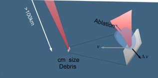
When the laser, with a higher intensity than a specified ablation threshold, is focused on the debris surface, the material of the debris is ejected as ablation plasma. Because of the ablation plasma, the debris is decelerated, reducing its velocity by ∆v. This is a consequence of the conservation of momentum. This phenomenon is illustrated in Figure 3. When ∆v is large enough, debris will re-enter the Earth’s atmosphere. When the laser operates over large distances, the pulse energy is limited, as a result of diffraction. Namely, the light from a laser beam is always somewhat divergent.This means that the laser’s energy can no longer be focussed on the debris in case the debris is far away. The spinning effects or the orientation with respect to the laser pulse are not taken into account. Using high repetition laser pulses, the orientation and angular velocity of the debris can be determined. Once these characteristics are known, ablation can be executed for optimised laser ablation. [19]
Critical parts of the ISS
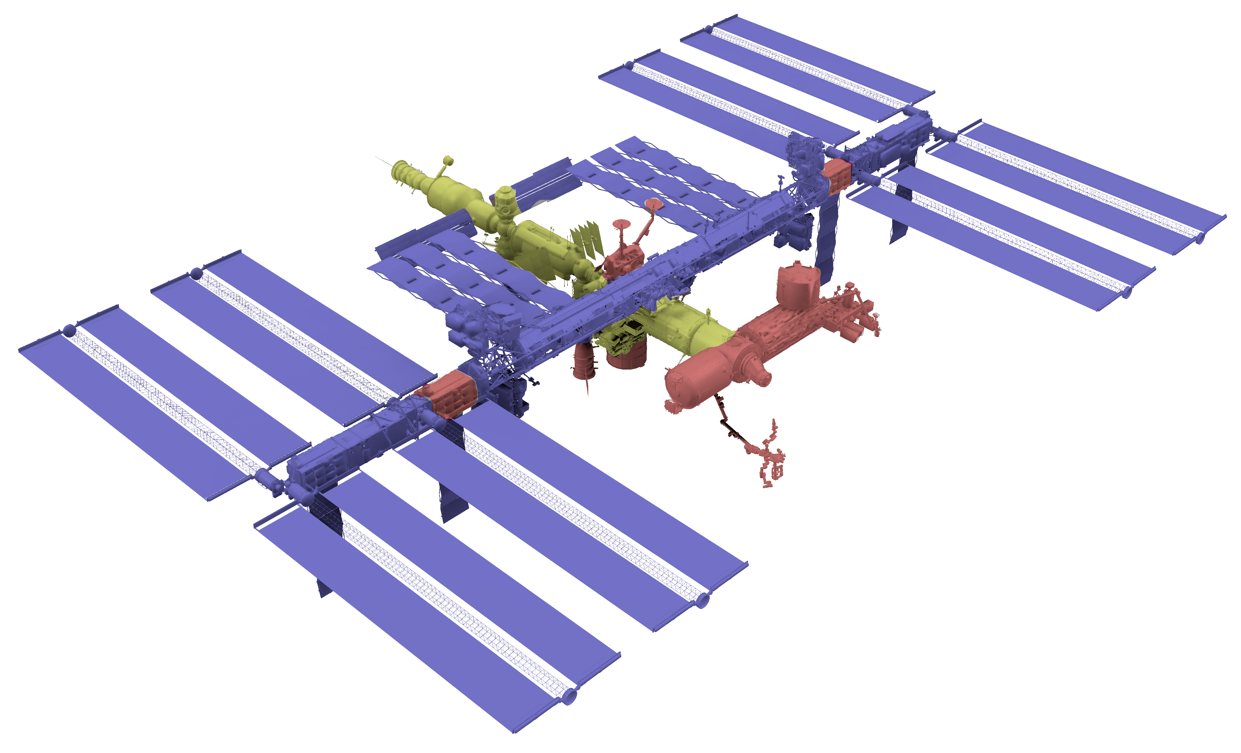
To consider the placement and number of lasers needed to protect the ISS the importance of the modules and components of the ISS must be considered. Too many lasers would be needed to cover the ISS and all its modules. This would make the financial and energy costs too high and therefore unfeasible. This is why priority has to be given to certain modules and components to make distinctions in the amount of protection they need, when considering the placement of the laser(s). This is done by taking into account multiple aspects which will be explained in the following paragraphs.
The ISS Partners have already applied and developed protection for small sized space debris and meteorites. Wipple shields protect critical parts of the ISS to prevent the loss of the critical functionality. These critical parts are not only essential life support components but also components with a lot of stored energy in them, like the pressurized storage tanks, located at the US’s quest airlock, for the liquid oxygen and nitrogen. If they leak, possible chemical reactions or explosions could even cause more harm than the original impact itself. The space station's gyroscopes, located at the Z1 truss, also have a lot of energy stored within the components. The spinning disks could cause damage to the space station if penetrated by a debris impact [25]. The ISS Partners are constantly assessing and mapping where on the space station impacts most frequently occur. Within this render you see that most of the impacts are coming from the front and impact the JEM, Node 1 and Columbus modules. These are also the parts of the ISS which are most protected by Stuffed Whipple shields. Most of the essential life-support systems are also not located in those modules [25]. The oxygen generation systems and water filtration components are located in Node 3 and in the Russian service module. It can also be observed that the solar arrays are not taken into account for the impact frequency render [26]. This might be because these modules are not as critical for life support and therefore are not considered in the threat assessment. As shown in Figure 4, the Soyuz and progress modules also have a considerable amount of impact threat.
The Li-ion battery modules also have a lot of stored energy. The life support systems rely upon the power they provide and therefore make them highly important when considering the laser coverage.
When considering the placement of the laser, one has to consider the directions the debris originates from, the placement of the critical components and the placement of units with high amounts of stored energy [25]. The protection of the solar arrays does not have to be taken into account, as mentioned above. It is almost impossible to precisely compare the importance for laser coverage for every individual ISS module. This is therefore not preferable. A better idea might be to categorize the different modules based on their importance to ISS’ missions and crew. Because one cannot compare the modules all individually, the ISS’ structures are divided in three categories (sorted to increasing importance for laser coverage):
- The first category includes the components/modules that are only of importance when considering financial damage and the indirect damage it could cause to the rest of the space station. The modules and parts of this category are marked blue [28].
- The second category includes the components/modules that have a low risk of debris impact and also have critical components and functionality or are inhabited by the astronauts. The modules and parts of this category are marked yellow [28].
- The third category includes firstly, the components/modules that have a high risk of debris impact and also have critical components/functionality or are inhabited by the astronauts and secondly, the components/modules that have lots of stored energy which after an impact, could become a bigger indirect threat to the rest of the space station. The modules and parts of this category are marked red [28].
Debris orientation
The mean altitude at which the ISS orbits earth varies at around 400 km, depending on the density of the atmosphere and operational circumstances. This means that the space station operates on a fairly low orbit within the low earth orbit (LEO). At this low altitude, drag makes space debris fall to the earth more, clearing the space of most space debris. However, due to the size of the ISS, it is still at risk of collisions. [29]
The velocity needed for a stable orbit at the altitude of the ISS is about 7.7 km/s, which is also roughly the velocity of the space debris that could hit the ISS. When debris travels in the same direction and orbit as the ISS, it will probably never do damage. They would almost never collide and even if they did, the relative velocities of the collisions would be too low to cause any major damage. However, most debris that could hit the ISS does not travel in the same direction as the ISS. Since the debris in an orbit around Earth are not all at the exact same altitude and do not all have the same direction. The approach of the debris to the ISS can come from any direction.
However, not all debris that can hit the ISS originates from a stable orbit. When the velocity of something in orbit is too low, it will fall down to Earth. This could lead to a collision with the ISS on their path down to Earth. The chance of collision from debris or another object from below the ISS is nihil. Therefore this will not be taken into consideration in the model.
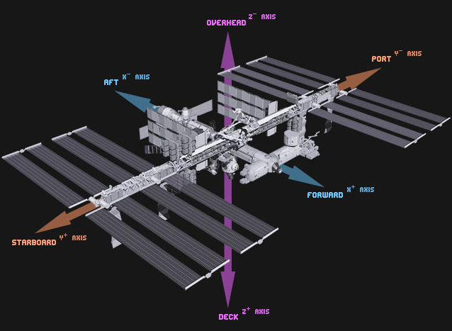
The debris going in the same direction as the ISS will not have a high relative velocity to the ISS, so it is likely that this will result in no to very little damage. In a head on collision, the impact velocity can be up to 16 km/s, which is roughly twice the stable orbit velocity at the height of the ISS. Figure 5 shows the different directions relative to the ISS. In conclusion. the directions dangerous debris can come from are the forward, overhead, starboard and port directions or combinations of these.
Laser(s) placement
It is crucial to determine where exactly on the ISS the lasers should be placed. Many aspects must be taken into account. Firstly, the laser must have a clear view of space, so that no part of the ISS itself gets in the way. Secondly, the laser must be attached firmly to the space station. Lastly, the laser system should be placed where it can be reached by the astronauts, so that potential maintenance can be performed, such as reparations.
The critical parts of the ISS were mentioned previously (see Critical Parts). In this chapter the different modules of the space station were distributed into different categories of importance. The modules which are marked red, are the most vulnerable to space debris. Therefore, the protection of these modules should have the highest priority. Such modules are mainly located at the frontside, the backside and some are in-between the solar panels. When determining the placement of the lasers, the focus is therefore on these red marked modules.
The model in Matlab is used to see how much debris is ablated when one or more lasers are located at different places. The best location for the lasers would be on the frontside of the ISS, because most debris is coming from the forward direction as mentioned before and the relative velocity of the debris heading towards the frontside is higher than debris coming from other directions. Furthermore, the modules at the frontside are all marked red. Also, at this spot the laser system has a free view of space and there is no imbalance because the laser is not very heavy compared to the ISS.
The azimuth angle of the laser is limited to a range of -162° to 162°. Since debris coming from higher orbits are rarer the higher the vertical angle and since they never come from a lower orbit, the vertical angle is limited to a range of 0 to 45°. As for the initial position of a laser, an angle of 0° and 22.5° with respect to the horizontal plane are considered. The value of 22.5° is chosen since this is in the middle of the vertical range of the debris. The laser can freely move in the horizontal and vertical direction from -90° to 90°, which is the largest possible range for the laser. Even though we have limited the range of the debris from 0 to 45°, the vertical range is chosen as large as possible, since debris may still come from an unexpected direction.
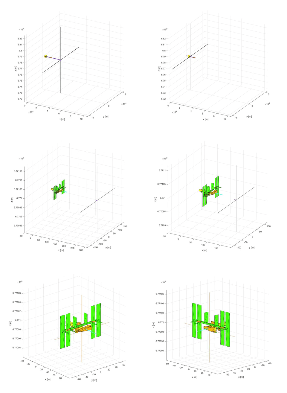
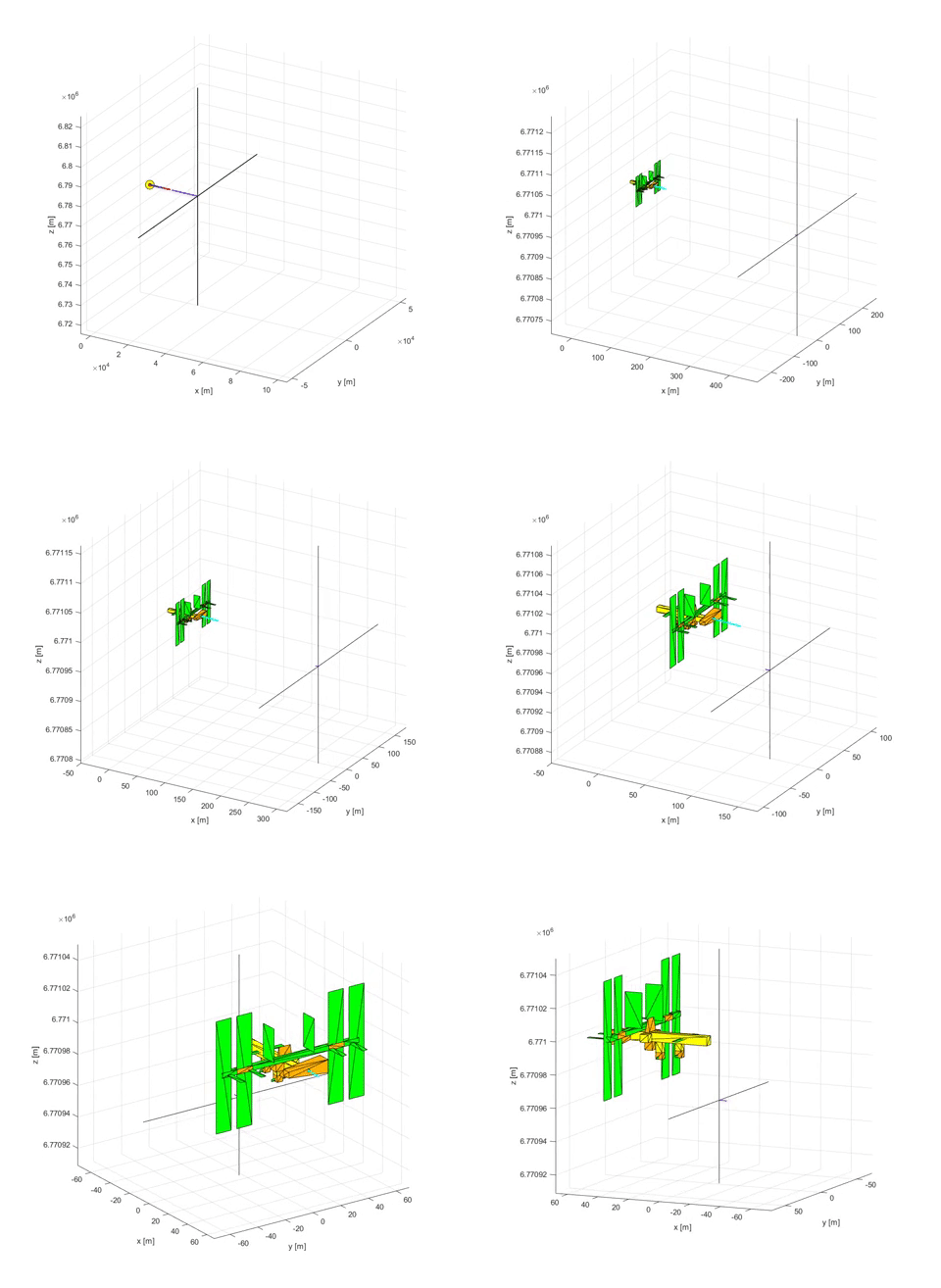
The different cases, which are illustrated in Figure 6, are:
- Case 1: One laser placed completely horizontally as initial position.
- Case 2: One laser inclined at an angle of 22.5° with respect to the horizontal plane as initial position.
- Case 3: Two lasers, both placed completely horizontally as initial position.
- Case 4: Two lasers, both inclined at an angle of 22.5° with respect to the horizontal plane as initial position.
- Case 5: Three lasers, which are all inclined with an angle of 22.5° with respect to the horizontal plane as initial position.
- Case 6: Three lasers, which are all inclined at an angle of 22.5° with respect to the horizontal plane, and the outer lasers are also inclined at an angle of 30° outward as initial position.
- Case 7: Three lasers, where the laser in the middle is placed horizontally, and the outer lasers are inclined at an angle of 22.5° with respect to the horizontal plane and with an angle of 30° outward as initial position.

Model
A very rough estimation of the plausibility of using lasers for the active protection of the ISS could be made, using some calculations. This could lead to results for a maximum diameter or velocity that can be stopped with a laser. While these can be very advanced and useful, they still fail to describe the full problem. With a model different situations can be simulated easily. This can help to determine whether or not the system works and when it does, different parameters of the ISS can be optimized. To make this model workable, assumptions and simplifications are needed.
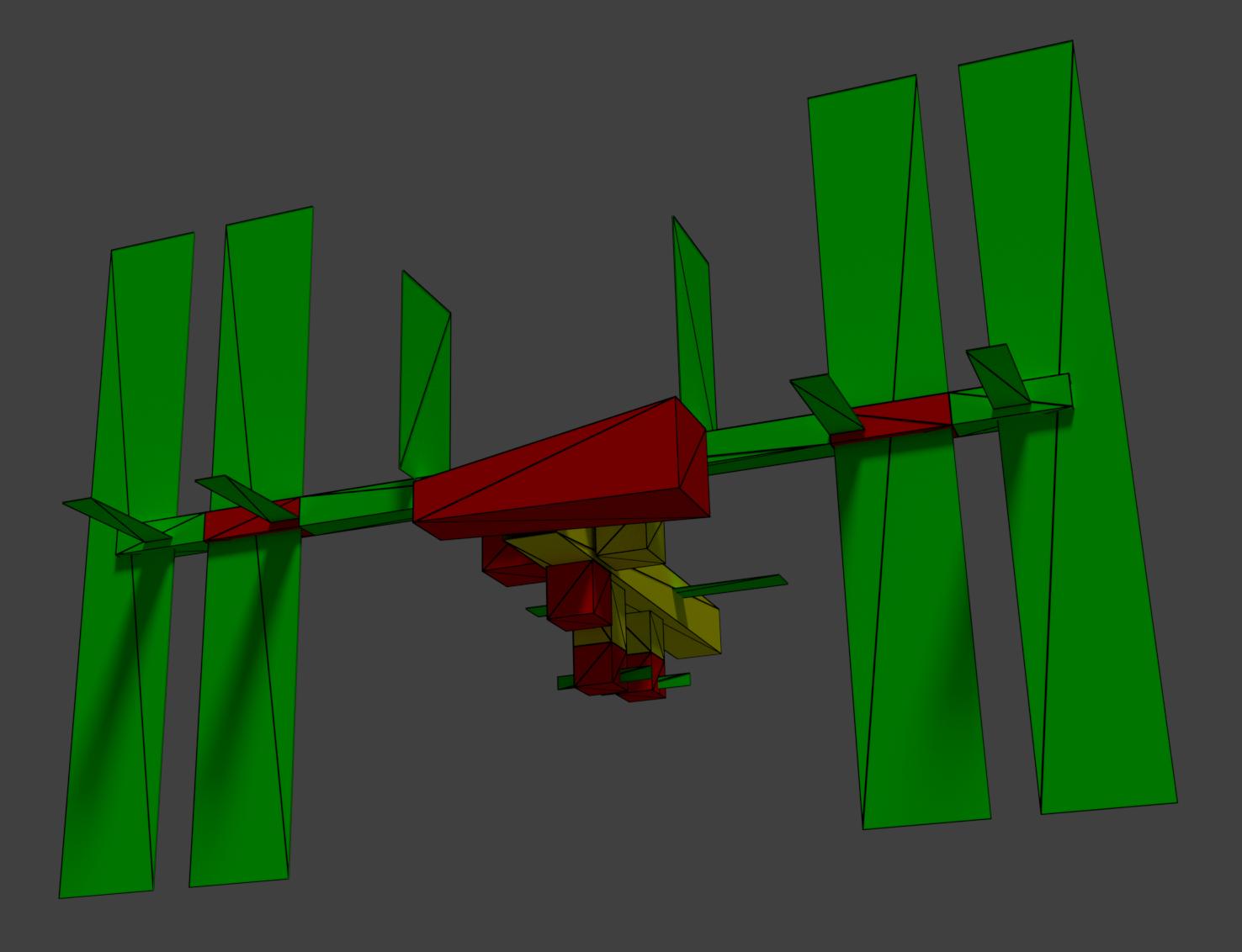
To register where debris hits, a 3D model of the ISS is needed. There are 3D models of the ISS available on the NASA website [30], which vary in detail and recency. The model from 2016 was chosen to replicate, since this is the most recent model. Blender was used to make a simplified triangle mesh version of the model, which can be seen in Figure 7. A python script exports this model to a separate file that can be imported into Matlab, where the rest of the simulation is built. To evaluate the need for batteries for the lasers, two different situations for available power are evaluated. In the first situation, the ISS has 158.4 kW available to distribute between the lasers that can shoot at their target. In the second situation, each laser is always capable to operate at its maximum power.
In the model, lasers are perfectly accurate, but have a rotation speed and a given starting orientation. Two different angles (horizontal and vertical) change with the given rotation speed to the angle needed to face the target debris. Each laser shoots a number of pulses per second, depending on the available energy for the laser. Each pulse has an energy of 10 J. The maximum number of pulses per second equals 10^4, for a maximum power of 100 kW per laser. If the laser has less power available than this maximum, the number of pulses per second is adjusted. These adjusted values and the coupling coefficient are used to determine the extra force on the debris due to the laser.
Movement of a debris particle is simulated using Newton’s laws of motion and kinematic equations for a uniform acceleration. A small time interval is used to describe the orbit of a debris particle accurately enough for the purposes used in this project. Additional forces, caused by the laser ablating the debris, can be added to determine the new path when one or more lasers fire at the debris. The movement of the ISS is subtracted from this movement, because this is easier to model. Since the motion of the debris is described in a collection of straight lines, a ray-triangle intersection algorithm can be used to determine where the debris hits the ISS. In this model, the Möller–Trumbore intersection algorithm [31] is used, where the movement of the ISS is also included in the direction of the debris.
The debris is defined by giving it a origin direction and an approximate position where it will hit the ISS. This origin direction Is given by a horizontal angle and a vertical angle and represents the movement direction of the debris relative to the earth when it hits the ISS. The debris is placed at the given position and the simulation determines what the path of the debris would be if it would hit at the given end position with the given origin direction and a velocity of 7.7 km/s. It then places it on that path at a distance of 100 km from the ISS, which is the range of the detection and laser here. The simulation with reactions to the lasers can now run. The mass of the debris is calculated using the mass model used by Shuangyan et al. [27], where a debris particle with a diameter of 10 centimeters has a mass of 70 g and the mass is proportional to d^2.26.
To evaluate the different laser configurations, the model tests different combinations of debris diameter, origin directions and end positions. Since debris with a movement direction close to that of the ISS will pose no threat and debris rarely comes from very high angles, the origin direction is limited. The horizontal angle of origin equals 0 when the debris and the ISS have the opposite movement directions. An angle from 180° would have the same movement direction. This horizontal direction is limited to a range of -175 to 175°, since anything outside that range does not pose a danger. The vertical angle equals 0 when debris is in a stable orbit around the earth at the same height as the ISS. A higher angle represents the debris coming from a higher orbit. As previously mentioned, this can vary from 0 to 90°. In the simulations, this angle is varied between 0 and 45°, since debris from higher angles is rare. The diameter is varied between 1 and 10 centimeters. The approximate end position of the debris is varied to hit different parts on the ISS.
The code can be found on GitHub: https://github.com/RobdeMooij/0LAUK0_USE_group_9

Results
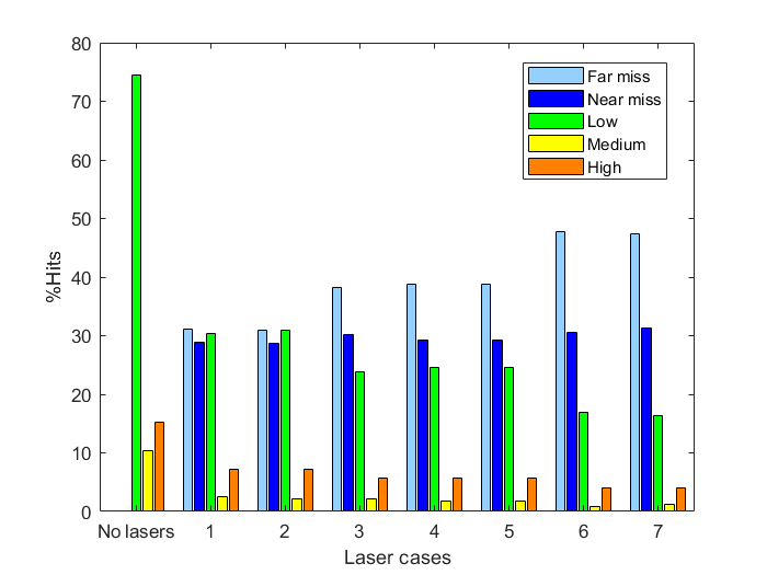
The total percentages of impact positions from the total amount of debris that would collide with the ISS when no laser is used, is shown in the bar graph below. In case debris is not predicted to hit the ISS but comes closer to it than 1 km, it is classified as a ‘near miss’.
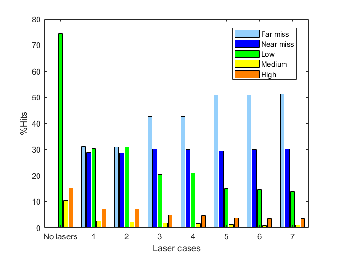
It can be derived from the figure that the addition of a laser system can significantly reduce the number of predicted collisions. Upon addition of the first laser, approximately 60% of predicted collisions can be prevented successfully. However, about half of these prevented collisions will still be classified as a near miss. Additional laser placement further improves protection, mostly resulting in increased ‘far misses’ and decreased low-risk collisions. For both the configurations with one and two lasers, the standard and tilted configuration perform (approximately) equally well.
In the tilted configuration, lasers are capable of reaching debris from varying directions more easily. Since the elevation ranges from 0 to 45°, the angle of these lasers is exactly centered to the directions in which threatening debris can approach. However, debris heading for a frontal collision move towards the ISS with a higher velocity with respect to the ISS then debris approaching from an elevation angle larger than 0. Therefore, the laser(s) must be aimed at debris in the orbit of the ISS much quicker to allow for remediation. It appears that these advantages of the considered configurations cancel out one another, resulting in equal performance.
Adding a third laser system in the tilted configuration does not seem to provide any added defense. This makes sense, as the limiting factor for laser ablation is the total available energy for the laser systems. When all lasers are initially aimed in the same direction, they rotate towards incoming debris more or less as a single unit. Since only a total of 158.4 kW is available for all lasers combined, using more than two lasers with the same initial angle will not provide further protection. In fact, employing two laser in the same directions at their maximum power is already quite inefficient. Therefore, the lasers should be aimed at different directions in order to prevent more collisions, as can be observed in the figure. This once again results in an increased number of ‘far misses’ and decreased low-risk collisions (around 10% of all collisions that would occur without using lasers).
Allowing all lasers to operate on their maximum power (without setting a limit imposed by the current total energy available on the ISS) further contributes to the defensive capabilities of the system, although this effect seems to be quite small. Especially for employing three laser systems, one might have expected a significant decrease in collisions. However, it seems that many of the debris particles one or two lasers fail to protect against, can also not be remediated using three lasers. It can also be observed from the figure that the defensive capabilities of laser systems are approximately equal within all configurations for each number of lasers. In this case, the lasers moving ‘as a single unit’ is not necessarily inefficient, as all lasers can function at their maximum power.
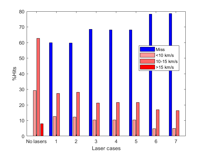
In the figure below, the impact velocities of debris heading for collision are categorized in ‘low’ (< 10 km/s), ‘medium’ (10-15 km/s) and ‘high’ (>15 km/s) velocity. It can be observed that all high-speed collisions can be prevented using one or more laser systems. Medium-speed collision are decreased more than 50% by adding a single laser system and can be decreased further (to a much smaller degree) by adding more lasers. Therefore, even though the laser systems cannot protect the ISS from all debris, it can at least result in considerably less dangerous collisions.
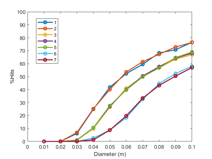
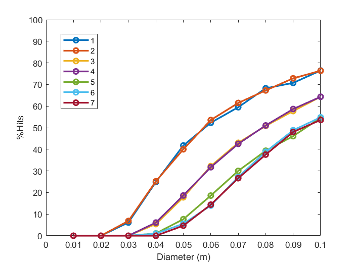
In the figure below, the percentages are plotted to the diameter of the debris. It can be derived that the performance of various laser configurations with the same number of laser show equal dependence on debris diameter, which is not strange. Small debris can be remediated easily, even by only a single laser. Addition of lasers proves to mostly be useful for defending against debris of a diameter of at least 4 centimeters. However, large debris continues to pose a large threat. Debris of a 10 centimeters diameter can still only be remediated in 40% of all cases by three lasers. This percentage can be increased to approximately 50% when removing the constraint imposed by the current total laser energy available on the ISS.
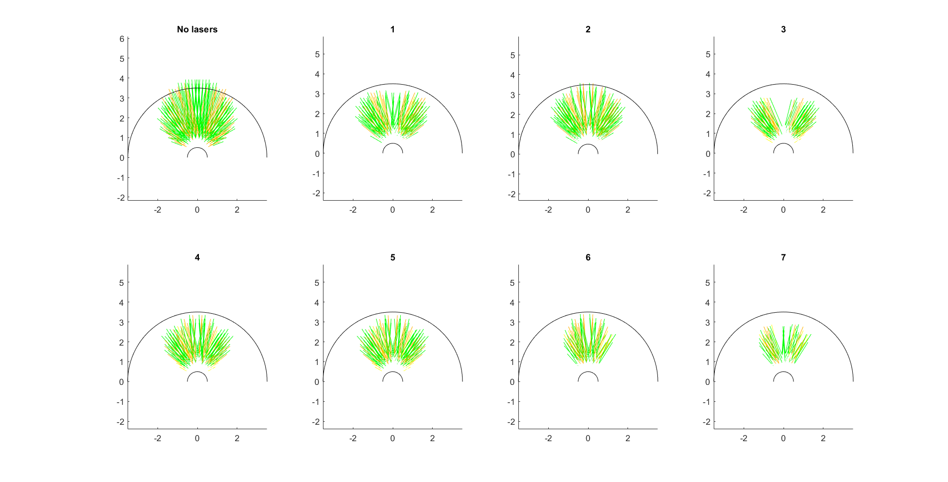
In the figure below, the ‘blind spots’ of the laser configurations can be observed in more detail. Clearly, addition of one laser already significantly decreases the density of incoming orbital debris. In particular, a significant drop in kinetic velocity of particles heading for (nearly) frontal collision can be observed. This makes sense, as the laser is also initially aimed in this direction. When looking only at an elevation angle of 0°, the tilted configuration performs worse than the default configuration. This becomes especially apparent when using two lasers: most debris headed straight for the ISS can be remediated completely by lasers initially aimed in the orbit of the ISS. This is clearly not the case when these are initially tilted upwards. Once again, due to the energy constraint imposed by the ISS, adding a third laser doesn’t immediately improve the effectivity of the defense system. However, when two lasers are aimed outwards, it can be clearly observed that the system has a much better chance of deorbiting debris coming from larger azimuth angles.
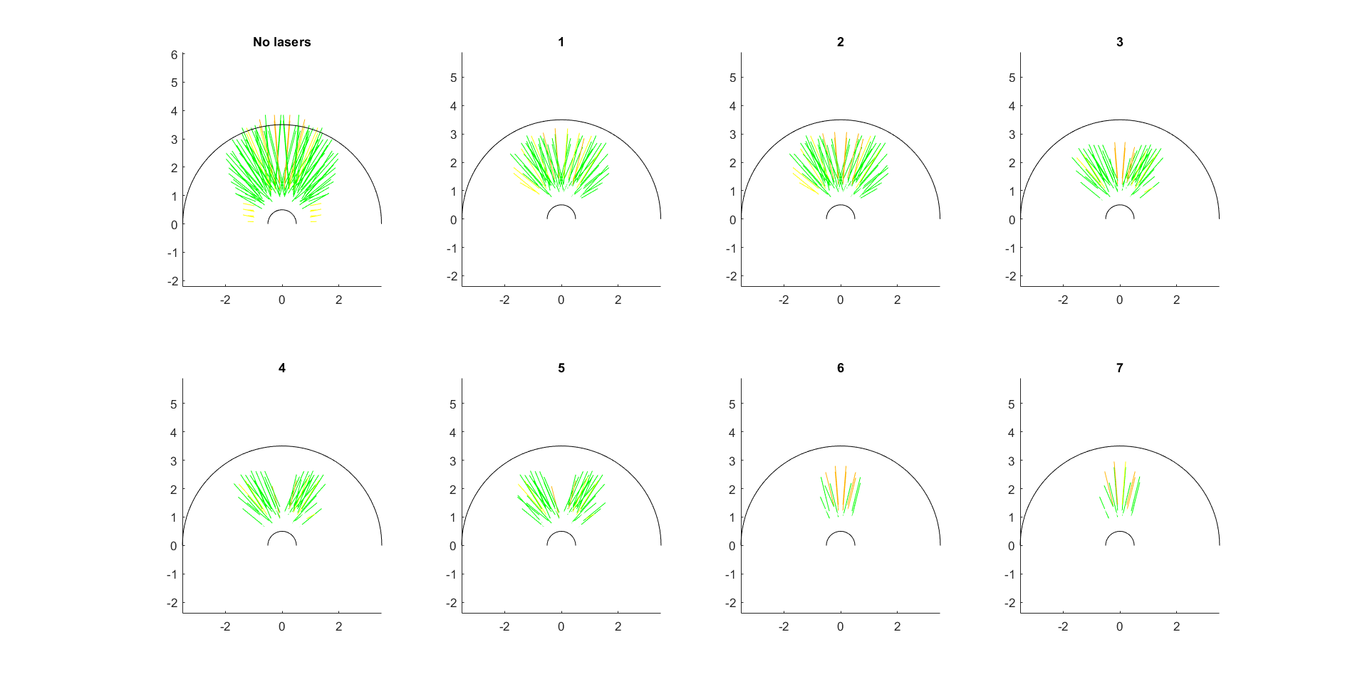
In contrast, it can be observed that the laser in tilted configuration generally perform somewhat better when considering higher elevation angles. For example, employing two tilted laser results in more effective reduction of frontal collision than two lasers directed in the orbit of the ISS (as can be seen by comparing case 3 and 4).
Discussion
As mentioned before, the 3D model of the ISS in Matlab is simplified, which means the actual ISS is way more detailed. Thus, it is important to realize that some details were overlooked when determining the placement of the lasers. Furthermore, many assumptions were made when making the model. The described path of the space debris may not be completely realistic, because the exact direction, velocity, size and mass of the debris moving towards the ISS is unpredictable or unknown. Also the spin of the debris has not been taken into account, while debris with spin may have a different collision impact. Moreover, the placement of the laser was easily done within the model in Matlab. However, the placement of a real CAN laser on the ISS is probably a lot of effort in practise. Moreover, there are no rulesets or legal frameworks on the placement of weapons in space and/or on the ISS laid out yet. This means that the assumptions made on the development and ownership of the system are not conclusive.
USE Scenario
In this part a possible USE-scenario will be explained. In this scenario the development, ownership and control is (mostly) by ESA. How this would be done, will be explained in the paragraphs below:
Development
According to the judicial rules set out by the legal framework of the ISS, the agency that develops a module for the ISS will retain ownership of it once it is attached to the space station [1]. Therefore it is possible that the laser system would be developed by only one space agency. However, this does not mean that it should be.
The ISS is one of the if not the biggest multinational cooperative project in the world. Since its convention the manufacturing of the ISS had engineers from different countries working together. Even the once biggest, rivaling great powers (Russia/USSR and USA) are working closely together on the ISS. In the past, the manufacturing of the modules saw the same cooperation. While for example one space agency was leading the development of a module, its parts could be built by engineers from all around the world. Moreover, all the participating space agencies (five) have insight in the operations of the agency in lead of the project. Lastly, the leading agency oversees the manufacturing of the modules and can also contract companies (both national and international) to build them [2].
All of this would be the same for the manufacturing of the laser system. In this example scenario the overseeing agency would be ESA. This would be the logical option since the CAN laser system is a system funded by the EU and currently developed by several European research institutions [3]. To continue this European cooperation the ESA can become the overseeing agency during the further development of this laser system. After doing so the agency can contract the institutions that had worked on the project before. The ESA also has the budget (six billion euros) to develop the project [4]. During this development the other space agencies will be able to have insight on the manufacturing of the project.
Ownership, control and management
As said in the previous paragraph in the ISS’ legal framework the following is said: 'each partner shall retain jurisdiction and control over the elements it registers in or on the Space Station'. Since in this scenario ESA will register the laser module it shall retain the jurisdiction and control over the system [1]. ESA has their own control centers in Europe. One of these could be assigned to control and manage the system. The control center will for example have to communicate to the astronauts when repairs are necessary to the system [5].
System usage and feedback
While the system’s control is in the hands of ESA this does not mean that the other agencies cannot have insight in the system’s actions. Instead ESA can give reports to the agencies about the performance of the system. It is not necessary to send these reports in full detail, but openness about the system’s actions would improve collaboration on the ISS. Like it always has done. It is likely that the activation of the system will also be communicated to the astronauts. However, full reports here are also not necessary since the astronauts are occupied with their research. Instead a situation that is comparable with the feedback given on the evasive maneuvers that are nowadays being performed, would be applicable.
The feedback from the system given to the control center would entail data on the detection of the debris, the effectiveness of the 'shot' and of the path of the debris after the 'shot'. Especially the latter is important since the debris might hit other satellites or pieces of debris on its (now accelerated) way down to earth. Avoiding these 'follow-up' collisions is possible however. The radars on earth have the ability to track debris above ten centimetres, as was mentioned above. If our system would have access to this data it could be able to calculate its 'shots' in a way that the piece of debris on collision course with the ISS would not hit any big pieces of debris on its now accelerated way down to earth.
User scenario
To further elaborate the control, management, system usage and feedback in this paragraph a possible user scenario will be described. In this scenario a piece of debris of unknown origin and of five centimeters in diameter is on course to crash into the ISS. It is coming at high speed head on towards the space station. With an impact speed of ten km/s the damage could be catastrophic after impact.
The proposed system however detects the object one hundred kilometers away from the space station. The system now has a maximum of ten seconds to ablate the object. During this process the system uses and depletes its power from its allocated batteries. The speed of the debris is now decreased in such a way that it de-orbits and will burn op in Earth’s atmosphere soon.
In this whole scenario the astronauts and control center do not notice what is happening and thus do also not have to act as to help the system ablate the piece of debris. Instead the system operates fully autonomously. After the successful ablation of the debris the system creates a log file and sends it to the ESA control center. Mission control then analyzes the file and sees if the system operated and is still operating as it should be. Mission control will not send the log file to the astronauts since they have no benefit from knowing all the details of the system’s actions. However mission control will notify the astronauts of the successful ablation as to reaffirm their safety in the space station. The file or a report of the file however will be send to the other ISS Partners as to improve co-operation.
After the system has sent the log file the batteries of the system also start recharging. Through the gathered energy from the solar panels the batteries will recharge. However, if it so happens that another piece of debris is detected and should be destroyed the system can still use the available energy allocated for non-vital systems such as energy for devices for food preparation, physical exercise etcetera. There will still be energy available for life-support and the laboratories however. So, if this happens astronauts will for example notice lights going off and their treadmill to stop working. The chance of two pieces of debris crashing into the ISS in a timespan of hours is very, very small however. The chance of collision between the ISS and a piece of space debris is ‘only’ seven percent per year according to an estimate in 1998 [6]. Since this chance is so small the choice was made to only allocate batteries to the system for one ablation.
References
2. https://www.britannica.com/topic/International-Space-Station
3. https://cordis.europa.eu/project/rcn/102392/reporting/en
4. https://www.esa.int/spaceinimages/Images/2019/01/ESA_Budget_2019
Conclusion
The International Space Station (ISS) faces a severe problem, which is space debris that may potentially damage it. This problem is tackled in this research, where we have focused on space debris with a diameter between 1 and 10 centimeters, for this is the most dangerous to the ISS. The proposal which is discussed will affect the astronauts which are in the space station, as well as the ground-based ISS control centers. Different techniques for active removal of debris are compared and the laser system has become the most optimal choice. These laser systems are already used for active removal of space debris, but not for direct protection of the ISS. They are capable of ablating small debris in the low Earth Orbit and have a great range. We have chosen for the Coherent Amplification Network (CAN) laser, which is the superior choice for remediation of debris of our size range. It has many advantages: it is able to remediate debris with high relative velocities (of more than 10 km/s), has a high electrical efficiency, a fast response and a high average power.
We wanted to determine the most optimal solution in terms of feasibility and effectiveness of the laser system. This is tested with a model made with Matlab, where a simplified representation of the ISS and incoming debris are modelled. The different laser(s) placement(s) are based on the critical parts of the ISS and the fact that more dangerous debris impacts will occur at the front of the ISS because of the high relative velocity. These placement of various lasers are examined. Various results can be obtained from the model, regarding the total percentages of impact positions from total amount of debris with the ISS against the different laser cases and diameter. Also, the effect of debris of different velocities is examined for all the laser cases. These results are likewise shown for the case if there is unlimited energy available for the laser systems.
From the results can be concluded that the addition of two laser systems on the front-side of the ISS is the most effective option. Namely, the debris which reaches high risk parts of the ISS is reduced significantly and the debris that misses the ISS is increased a lot, compared to a single laser. The standard and the tilted configuration perform (approximately) equally well. A third laser hardly adds extra defense and therefore this is not necessary. However, it is possible that the technology of the laser is improved in the future and that the costs are reduced. In this case, it may be a viable option to implement more than two lasers, in order to add extra defense to the ISS.
Although the focus is mostly on the laser ablation system, it is important to realize that a proper detection system is required to locate the space debris, since only then the debris can be disarmed effectively. Thus, the detection method is one of the aspects which must be addressed in further research.
Milestones and Deliverables
Milestones
| Week | Milestone |
|---|---|
| 2 | Determined subject; defined plan |
| 3 | Finish literature search about state of the art; determine problem statement |
| 4 | Specify method and USE aspects |
| 5 | Start model in Matlab |
| 6 | Run simulations with the model in Matlab |
| 7 | Results model, implement model in USE |
| 8 | Discussion, conclusion |
| 9 | Presentation, finish wiki |
| 10 | Deliver wiki |
Deliverables:
- Wiki page
- Presentation
- Model/prototype
Planning
| Week | Task | Responsible member(s) |
|---|---|---|
| 2 |
|
|
| 3 |
|
|
| 4 |
|
|
| 5 |
|
|
| 6 |
|
|
| 7 |
|
|
| 8 |
|
|
| 9 |
|
|
| 10 |
|
|
References
[1]Dunbar, B. (2015, June 01). What Is Orbital Debris? Retrieved June 22, 2019, from https://www.nasa.gov/audience/forstudents/5-8/features/nasa-knows/what-is-orbital-debris-58.html
[2]Hall, Loretta, "The History of Space Debris" (2014). Space Traffic Management Conference. 19. https://commons.erau.edu/stm/2014/thursday/19
[3]Jia, B., Liao, G. J., Gong, H. P., & Pang, B. J. (2010). Experimental Investigation and Numerical Simulation of Porous Volcano Rock Hypervelocity Impact on Whipple Shield of Spacecrafts. Key Engineering Materials, 452-453, 385-388. doi:10.4028/www.scientific.net/kem.452-453.385
[4]Senate bill seeks extension of the space station. (2019, February 28). Retrieved June 22, 2019, from https://spacenews.com/senate-bill-seeks-extension-of-the-space-station/
[5] Garcia, M. (2019, March 21). International Space Station Facts and Figures. Retrieved from https://www.nasa.gov/feature/facts-and-figures
[6] United States. (2015). Reference guide to the International Space Station.
[7] NASA Johnson Space Center, Orbital Debris Program Office, ORBITAL DEBRIS EDUCATION PACKAGE [PowerPoint]. https://web.archive.org/web/20080408183946/http://www.orbitaldebris.jsc.nasa.gov/library/EducationPackage.pdf
[8] Hutchinson, L. (2013, July 04). How NASA steers the International Space Station around space junk. Retrieved from https://arstechnica.com/science/2013/07/how-nasa-steers-the-international-space-station-around-space-junk/
[9] Rainey, K. (2015, April 01). Space Station Research Experiments. Retrieved from https://www.nasa.gov/mission_pages/station/research/experiments_category
[10] National Aeronautics and Space Administration. (2012) Research in Space 2013 and Beyond [Brochure]. N.P.: NASA ISS Program Science Office.
[11] ESA. (2013, November 19). International Space Station legal framework. Retrieved from http://www.esa.int/Our_Activities/Human_and_Robotic_Exploration/International_Space_Station/International_Space_Station_legal_framework
[12] Lafleur, C. (2010, March 8). Costs of US piloted programs. Retrieved from http://www.thespacereview.com/article/1579/1
[13] P. Colmenarejo, M. Avilés, and E. di Sotto, “Active debris removal GNC challenges over design and required ground validation,” CEAS Sp. J., vol. 7, no. 2, pp. 187–201, 2015.
[14] V. Dubanchet, D. Saussié, D. Alazard, C. Bérard, and C. Le Peuvédic, “Modeling and control of a space robot for active debris removal,” CEAS Sp. J., vol. 7, no. 2, pp. 203–218, 2015.
[15] M. Andrenucci, P. Pergola, and A. Ruggiero, “Active Removal of Space Debris,” pp. 1–132, 2011.
[16] B. Esmiller, C. Jacquelard, H.-A. Eckel, and E. Wnuk, “Space debris removal by ground-based lasers: main conclusions of the European project CLEANSPACE,” Appl. Opt., vol. 53, no. 31, p. I45, 2014.
[17] I. Beam, “Engineering N otes,” vol. 34, no. 3, 2011.
[18] T. Ebisuzaki et al., “Acta Astronautica Demonstration designs for the remediation of space debris from the International Space Station,” Acta Astronaut., vol. 112, pp. 102–113, 2015.
[19] C. R. Phipps, “LADROIT - A spaceborne ultraviolet laser system for space debris clearing,” Acta Astronaut., vol. 104, no. 1, pp. 243–255, 2014.
[20] ESA. (2013, November 19). International Space Station legal framework. Retrieved from http://www.esa.int/Our_Activities/Human_and_Robotic_Exploration/International_Space_Station/International_Space_Station_legal_framework
[21] Robert.wickramatunga. (n.d.). United NationsOffice for Outer Space Affairs. Retrieved from http://www.unoosa.org/oosa/en/ourwork/copuos/index.html
[22] DeFrieze, D. (2014). Disarmament Treaties Database: Outer Space Treaty. (n.d.). Retrieved from http://disarmament.un.org/treaties/t/outer_space
[23] Defining and Regulating the Weaponization of Space. Retrieved from https://ndupress.ndu.edu/Portals/68/Documents/jfq/jfq-74/jfq-74_110-115_DeFrieze.pdf
[24] Laser ablation. (2019, January 08). Retrieved from https://en.wikipedia.org/wiki/Laser_ablation
[25] National Research Council. 1997. Protecting the Space Station from Meteoroids and Orbital Debris. Washington, DC: The National Academies Press. https://doi.org/10.17226/5532.
[26] A. (n.d.). Orbital Debris Management & Risk Mitigation. NASA. Retrieved June 9, 2019, from https://appel.nasa.gov/wp-content/uploads/2013/04/692076main_Orbital_Debris_Management_and_Risk_Mitigation.pdf
[27] Shen, S., Jin, X., & Hao, C. (2014). Cleaning space debris with a space-based laser system. Chinese Journal of Aeronautics, 27(4), 805–811. https://doi.org/10.1016/j.cja.2014.05.002
[28] N. (2015). REFERENCE GUIDE TO THE SPACE STATION INTERNATIONAL. NASA. Retrieved June 9, 2019, from https://www.nasa.gov/sites/default/files/atoms/files/np-2015-05-022-jsc-iss-guide-2015-update-111015-508c.pdf.
[29] Protecting the Space Station from Meteoroids and Orbital Debris. (1997). https://doi.org/10.17226/5532
[30] International Space Station. (2015, June 8). Retrieved from https://nasa3d.arc.nasa.gov/detail/iss
[31] Möller–Trumbore intersection algorithm. (2019, June 17). Retrieved from https://en.wikipedia.org/wiki/Möller–Trumbore_intersection_algorithm
State of the art references
- Dubanchet, V., Saussié, D., Alazard, D., Bérard, C., & Peuvédic, C. Le. (2015). Modeling and control of a space robot for active debris removal. CEAS Space Journal, 7(2), 203–218. https://doi.org/10.1007/s12567-015-0082-4
This paper focusses on the technical aspects of using a robotic arm on a ‘chaser’ satellite to capture large debris. This approach is considered to be the most realistic to actually be employed in the upcoming years. In the introduction, several efforts in achieving the modeling and control of such a system (in space) are outlined. In the second section, the main issues in achieving this are described. In the third and fourth section, an algorithm used to model and simulate the dynamics of this satellite and the method of controlling it are described. The resulting system is then simulated using Matlab (the code is provided in the paper).
- Flegel, S., Krisko, P., Gelhaus, J., Wiedemann, C., Möckel, M., Vörsmann, P., … Matney, M. (2010). Modeling the Space Debris Environment with MASTER2009 and ORDEM2010. Proceedings of the 38th COSPAR Scientific Assembly, (January).
This paper describes and compares two software tools (MASTER-2009 and ORDEM2010 developed by ESA and NASA respectively) used to describe debris orbiting the earth. The main goal of these tools is to estimate the object flux onto a specified target object and is therefore useful in achieving safe space travel. In MASTER, debris is simulated based on lists of known historical events responsible for scattering debris in earth’s orbit. Results are also validated using historical telescope/radar data. ORDEM is designed to reliably estimate orbital debris flux on spacecraft using telescope or radar fields-of-view. Therefore, both programs make heavy use of empirical data for their predictions. Results of the program deviate particularly in debris with a size of 1 millimeter to 1 centimeter. These bits of debris are particularly difficult to model, as the amount of measurement data is very small. Reasons for the deviation of the results for these small debris are described in the paper.
- Klinkrad, H. (2006). Space debris : models and risk analysis. Springer.
This book extensively covers space debris in general and describes the technical aspects of this debris in detail. In chapters 2 to 6, it is outlined how the space debris environment can be characterized and modelled using measurement data. Furthermore, it is explained how the future of space debris orbiting earth can be predicted and how this could be influenced by mitigation measures. Chapters 7 to 9 describe aspects of risk assessment and prevention within on-orbit shielding, collision avoidance and re-entry risk management. Chapter 10 gives an overview of the risks associated with natural meteoroids and meteorites. Lastly, chapter 11 overviews the importance of space debris research and international policy and standardization issues.
Understanding the causes and controlling its sources is essential to allow for safe space flight in the future. This can only be achieved through international cooperation. This has been done through international information exchange and international cooperation at a technical level. Furthermore, steps have already been taken in establishing space debris mitigation standards, guidelines, codes of conduct and policies by several space agencies, governmental bodies and international space operators.
- Yazdkhasti, S., & Sasiadek, J. Z. (2017). Space Robot Relative Navigation for Debris Removal. IFAC-PapersOnLine, 50(1), 7929–7934. https://doi.org/10.1016/j.ifacol.2017.08.767
In order for a ‘chaser’ (spacecraft capable of removing space debris) to properly navigate towards its target, it must be able to estimate the pose and motion of the target. In the introduction, several works addressing this problem are outlined. This paper presents a method to estimate the relative position, linear and angular velocity and the attitude of space debris using vision measurements (using stereo cameras). In order to estimate the relative states between spacecraft, the Multiplicative Extended Kalman Filter and Unscented Kalman Filter were applied. The methodology is described by first outlining the coordinate systems used. Afterwards, the estimation algorithm is described (in which a set of feature points tracked by a stereo camera are key). Then, the described algorithms are validated using a simulation experiment. This paper could be very interesting for our model. Perhaps we could translate the presented algorithm into a script and further build on it.
- Colmenarejo, P., Avilés, M., & di Sotto, E. (2015). Active debris removal GNC challenges over design and required ground validation. CEAS Space Journal, 7(2), 187–201. https://doi.org/10.1007/s12567-015-0088-y
In this paper, proposed techniques for active debris removal (ADR) are categorized as follows:
- Contactless techniques (e.g. an ion beam), which can mostly build on existing techniques as opposed to using new ones
- Techniques requiring rigid contact (e.g. through a robotic arm), in which de-orbiting can be achieved by directly transmitting a force/torque to the debris
- Techniques requiring non-rigid contact (e.g. using flexible tentacles), which can entail intricate dynamics
A list of the proposed techniques can be retrieved from table 1 in the paper. As of yet, the most technologically advanced methods are the use of a robotic arm and capture through a tethered net.
Additionally, the main operational phases of active debris removal are outlined:
1. Ground controlled phase: In this phase, the “chaser” is brought closer to the target, usually not autonomously.
2. Fine orbit synchronization phase: The chaser moves to the (approximate) orbit of the target, which can be autonomous or partially using ground support
3. Short range phase: the final (passive) approach toward the target. Challenges here (which we could also address) are:
- Necessity to determine debris angular velocity and shape using optical observation, which most likely requires image processing techniques
- Necessity to synchronize the chaser with the angular motion of the debris
- In case of contact, necessity to de-tumble/control the resulting composite satellite
4. Terminal approach/capture
5. De-orbiting
Clearly, the fourth and fifth phase are very specific to the technique chosen for debris removal. Furthermore, the following aspects are discussed in the paper in detail:
1. Terminal approach using visual-based navigation
2. Ground validation of guidance, navigation and control systems based on hardware-in-the-loop test facilities
- Chen, S. (2011). The Space Debris Problem. Asian Perspective, 35(4), 537–558. https://doi.org/10.1353/apr.2011.0023
Near-Earth orbits are becoming congested as a result of an increase in the number of objects in space—operational satellites as well as orbital space debris. The risk of collisions between satellites and space debris is also growing. Suggested concepts for active removal of space debris: small-debris collection, ground-based lasers, trash tenders, dual-use orbit transfer vehicles, space-based lasers, and space tethers. There are two separate areas of concentration: small-debris elimination and individual large-object collection.
- Nishida, S.-I., Kawamoto, S., Okawa, Y., Terui, F., & Kitamura, S. (2009). Space debris removal system using a small satellite. Acta Astronautica, 65(1–2), 95–102. https://doi.org/10.1016/j.actaastro.2009.01.041
Electro-dynamic tether (EDT) technology, a possible high efficiency orbital transfer system, could provide a possible means for lowering the orbits of objects without the need for propellant.
- Ruggiero, A., Pergola, P., & Andrenucci, M. (2015). Small Electric Propulsion Platform for Active Space Debris Removal. IEEE Transactions on Plasma Science, 43(12), 4200–4209. https://doi.org/10.1109/TPS.2015.2491649
A deorbiting platform is in charge of approaching a target debris, bringing it to a lower altitude orbit and, in the case of a multiple target mission, releasing it and chasing a second one. Electric propulsion plays a key role in reducing the propellant mass consumption required for each maneuver and thus increasing the mass available to deorbit a relevant number of debris per mission.
- Huang, P., Zhang, F., Meng, Z., & Liu, Z. (2016). Adaptive control for space debris removal with uncertain kinematics, dynamics and states. Acta Astronautica, 128, 416–430. https://doi.org/10.1016/j.actaastro.2016.07.043
Tethered Space Robots are a promising solution for the space debris problem. Kinematics and dynamics parameters of the debris are unknown and parts of the states are unmeasurable according to the specifics of tether, which is a tough problem for the target retrieval/de-orbiting. Models and simulations can be used to get proposed parameters and their expected performances.
- Lampariello, R. (2013). On Grasping a Tumbling Debris Object with a Free-Flying Robot. IFAC Proceedings Volumes, 46(19), 161–166. https://doi.org/10.3182/20130902-5-DE-2040.00118
The grasping and stabilization of a tumbling, non-cooperative target satellite by means of a free-flying robot is a challenging control problem. A novel method for computing robot trajectories for grasping a tumbling target is presented. The problem is solved as a motion planning problem with nonlinear optimization. The resulting solution includes a first maneuver of the Servicer satellite which carries the robot arm, taking account of typical satellite control inputs. An analysis of the characteristics of the motion of a grasping point on a tumbling body is used to motivate this grasping method, which is argued to be useful for grasping targets of larger size.
- Klima, R., Bloemenbergen, D. (2016) Space debris removal: a game theoretical analysis https://www.mdpi.com/2073-4336/7/3/20
Space debris are a threat to operational spacecraft. Debris removal mission have been investigated by several space agencies to protect the satellites in the orbital environments. This costs a lot of money, but it has positive effect for all the satellites in the same orbital. A drawback is the agencies can all financially contribute to the debris removal or wait for others to do it. The risk of the latter is that the debris will be catastrophic. A game-theoretical analysis is presented where a realistic model of the orbit environment including all space objects are implemented. The experiments confirmed the predicted exponential growth of space debris near the Earth orbits. Active object removal are necessary.
- Liou, J.-C., Johnson, N. L. (2006). Risks in space from orbiting debris https://science.sciencemag.org/content/311/5759/340?casa_token=eKETqH8PDB4AAAAA:F0c9mUOMMHFELTaZbWngoc5wcDTKOkO0Ke0enr3v5kST6L-BQAsv6JItvTKWMiUkH2xrm2XAz7wm2Q
Since the launch of Sputnik I, an orbital debris environment has been created which has a risk on the space systems, including human space flight and robotic missions. More than 9000 orbiting objects with a total mass larger than 5 million kg are tracked by the U.S. Space Surveillance Network. Three collision have been occurred. There is a potential increase in Earth satellite population which results from the collisions of the space objects.
The current debris environment in the Low earth orbit (LEO) region is unstable and the collisions will become dominant in the future even without new launches. The collisions will happen between 900- and 1000 km over the next 200 years, which results in debris increase. Because undoubtedly new spacecraft will be launched in the future, the situation is even worse.
- Marco M. Castronuovo (2011)., Active space debris removal —A preliminary mission analysis and design, Pages 848-859, ISSN 0094-5765, https://doi.org/10.1016/j.actaastro.2011.04.017 .
(http://www.sciencedirect.com/science/article/pii/S0094576511001287 )
The removal of 5 to 10 objects per year from the LEO can prevent the debris collisions from cascading. There are three orbital regions near the Earth where the collision occur and the sun-synchronous condition is the one we should target for debris removal. For this removal, a space mission has been designed with the goal to remove 5 rockets per year from this orbital environment. This space mission includes the launch of a satellite which contains de-orbiting devices. This satellite chooses an objects and grabs it with a robotic arm. A second arm puts a de-orbiting device to the object. Then the next target can be done. An active debris removal mission can de-orbit 35 large objects in 7 years and the mass budget is compatible.
- Shin-Ichiro Nishida, Satomi Kawamoto, (2011). Strategy for capturing of a tumbling space debris,Pages 113-120,ISSN 0094-5765,
https://doi.org/10.1016/j.actaastro.2010.06.045 . (http://www.sciencedirect.com/science/article/pii/S0094576510002365 )
The capture of space debris objects are not favorable, because tracking errors lead to loading and momentum transfer occur during the capturing. Because the exact mass and inertial characteristics of the target are unknown due to unavailability or damage, it is harder to use the capture arm to capture the object. A “joint virtual depth control”algorithm for a force controlled robot arm control is used which tries to stop the rotation of the target with a brush type contactor. As a result, a new active space debris removal system is becoming more achievable.
- Vladimir Aslanov, Vadim Yudintsev, (2013). Dynamics of large space debris removal using tethered space tug, Pages 149-156, ISSN 0094-5765,
https://doi.org/10.1016/j.actaastro.2013.05.020 . (http://www.sciencedirect.com/science/article/pii/S0094576513001811 )
Tethered systems are promising technology to reduce the space debris. This is possible in different ways: through momentum transfer or electrodynamic effects. Another way is using a tethered space tug which is attached to the space debris. Large space debris can cause a loss of control of the tethered space tug, so the problem of the removal of this large space debris is studied. The transportation system consists of a space debris and a space tug which are connected by the tether. The properties of this system on the motion of the system are studied, which includes the moments of inertia, the length and properties of tether, thruster force and initial condition of motion. The transportation process is possible when the space tug force is in the same direction as the tether and the tether is tensioned. There is minimal height of safe transportation below which the space tug can come into collision with the space debris.
- Nishida, S., & Yoshikawa, T. (2007). Capture and motion braking of space debris by a space robot. 2007 International Conference on Control, Automation and Systems. doi:10.1109/iccas.2007.4406990
(https://ieeexplore.ieee.org/document/4406990)
Space debris objects are generally tumbling in orbit, and so capturing and braking them involves complicated dynamical interactions between the object, the so-called "servicer" spacecraft, and its robot arm, with the possibility of strong loading occurring during the procedure. In this paper, a space debris capture strategy is described which proposes the application of joint virtual depth control to the capture robot arm. We present the results of simulations and experiments that confirm the feasibility of this technique.
- Nguyen-Huynh, T. C., & Sharf, I. (2013). Adaptive Reactionless Motion and Parameter Identification in Postcapture of Space Debris. Journal of Guidance, Control, and Dynamics, 36(2), 404-414. doi:10.2514/1.57856
(https://arc.aiaa.org/doi/10.2514/1.57856)
This paper presents a new control scheme for the problem of a space manipulator after capturing an unknown target, such as space debris. The changes in the dynamics parameters of the system, as a result of capturing an unknown target, must be accommodated because they may lead to poor performance of the trajectory control and attitude stabilization system. To address this issue in the postcapture scenario, the adaptive reactionless control algorithm to produce the arm motions with minimum disturbance to the base is proposed in this study. In addition, the online momentum-based estimation method is developed for inertia-parameter identification after the space manipulator grasps an unknown tumbling target with unknown angular momentum. This control scheme is intended for use in the transition phase from the instant of capture until the unknown parameters are identified and/or the available stabilization methods can be applied properly. To verify the validity and feasibility of the proposed concept, MSC.Adams simulation platform is employed to implement a planar base–manipulator–target model and the three-dimensional model of the Engineering Test Satellite VII system. The numerical results show that the space manipulator is able to perform reactionless motion while the inertial parameters converge to their real values.
- Kessler, D. J., & Cour-Palais, B. G. (1980). Collision Frequency of Artificial Satellites: Creation of a Debris Belt. Space Systems and Their Interactions with Earth's Space Environment, 707-736. doi:10.2514/5.9781600865459.0707.0736
(https://agupubs.onlinelibrary.wiley.com/doi/abs/10.1029/JA083iA06p02637)
As the number of artificial satellites in earth orbit increases, the probability of collisions between satellites also increases. Satellite collisions would produce orbiting fragments, each of which would increase the probability of further collisions, leading to the growth of a belt of debris around the earth. This process parallels certain theories concerning the growth of the asteroid belt. The debris flux in such an earth‐orbiting belt could exceed the natural meteoroid flux, affecting future spacecraft designs. A mathematical model was used to predict the rate at which such a belt might form. Under certain conditions the belt could begin to form within this century and could be a significant problem during the next century. The possibility that numerous unobserved fragments already exist from spacecraft explosions would decrease this time interval. However, early implementation of specialized launch constraints and operational procedures could significantly delay the formation of the belt.
- Bennet, F., Conan, R., D’Orgeville, C., Murray, M., Paulin, N., Price, I., Rigaut, F., Ritchie, I., Smith, C., and Uhlendorf, K., “Adaptive optics for laser space debris removal”, in [SPIE Astronomical Telescopes+ Instrumentation], 844744–844744, International Society for Optics and Photonics (2012).
(https://www.researchgate.net/publication/258719228_Adaptive_Optics_For_Laser_Space_Debris_Removal)
Space debris in low Earth orbit below 1500km is becoming an increasing threat to satellites and spacecrafts. Radar and laser tracking are currently used to monitor the orbits of thousands of space debris and active satellites are able to use this information to manoeuvre out of the way of a predicted collision. However, many satellites are not able to manoeuvre and debris-on debris collisions are becoming a signicant contributor to the growing space debris population. The removal of the space debris from orbit is the preferred and more denitive solution. Space debris removal may be achieved through laser ablation, whereby a high power laser corrected with an adaptive optics system could, in theory, allow ablation of the debris surface and so impart a remote thrust on the targeted object. The goal of this is to avoid collisions between space debris to prevent an exponential increase in the number of space debris objects. We are developing an experiment to demonstrate the feasibility of laser ablation for space debris removal. This laser ablation demonstrator utilises a pulsed sodium laser to probe the atmosphere ahead of the space debris and the sun re ection of the space debris is used to provide atmospheric tip{tilt information. A deformable mirror is then shaped to correct an infrared laser beam on the uplink path to the debris. We present here the design and the expected performance of the system.
- Bradley, A. M., & Wein, L. M. (2009). Space debris: Assessing risk and responsibility. Advances in Space Research, 43(9), 1372-1390. doi:10.1016/j.asr.2009.02.006
(https://www.researchgate.net/publication/222563620_Space_debris_Assessing_risk_and_responsibility)
We model the orbital debris environment by a set of differential equations with parameter values that capture many of the complexities of existing three-dimensional simulation models. We compute the probability that a spacecraft gets destroyed in a collision during its operational lifetime, and then define the sustainable risk level as the maximum of this probability over all future time. Focusing on the 900- to 1000-km altitude region, which is the most congested portion of low Earth orbit, we find that – despite the initial rise in the level of fragments – the sustainable risk remains below 10-3 if there is high (>98%) compliance to the existing 25-year postmission deorbiting guideline. We quantify the damage (via the number of future destroyed operational spacecraft) generated by past and future space activities. We estimate that the 2007 FengYun 1C antisatellite weapon test represents ≈1% of the legacy damage due to space objects having a characteristic size of ⩾10 cm, and causes the same damage as failing to deorbit 2.6 spacecraft after their operational life. Although the political and economic issues are daunting, these damage estimates can be used to help determine one-time legacy fees and fees on future activities (including deorbit noncompliance), which can deter future debris generation, compensate operational spacecraft that are destroyed in future collisions, and partially fund research and development into space debris mitigation technologies. Our results need to be confirmed with a high-fidelity three-dimensional model before they can provide the basis for any major decisions made by the space community.