Embedded Motion Control 2019 Group 7
Group members
- Guus Bauwens - 0958439
- Ruben Beumer - 0967254
- Ainse Kokkelmans - 0957735
- Johan Kon - 0959920
- Koen de Vos - 0955647
Introduction
This wiki page describes the design process for the software as applied to the PICO robot within the context of the "Embedded Motion Control" course project. The project is comprised of two challenges: the escape room challenge and the hospital challenge. The goal of the escape room challenge is to exit the room autonomously as fast as possible. The goal of the hospital challenge is to autonomously visit an unknown number of cabinets as fast as possible.
Design Document
The design document, describing the initial design requirements, functions, components, specifications and interfaces, can be found here.
Requirements
Functions
Components
Specifications
Interfaces
Challenge 1: The escape room
As an intermediate assignment, the PICO robot should autonomously escape a room through a door from any arbitrary initial position as fast as possible.
To complete this goal, the following steps are introduced:
- The sensors and actuator are initialized.
- From the initial position, the surroundings are scanned for gaps between the walls. If no openings are found, the robot is to rotate until the opening is within view.
- The robot will drive towards a subtarget, placed at a small distance from the opening in order to avoid wall collisions.
- Once arrived at the subtarget, the robot will rotate towards the target.
- After being aligned with the target, the robot will drive straight trough the corridor.
To this end, methods for the detection of gaps between walls, the placement of (sub)targets and the path planning are required.
Gap detection

From the initial position, the surroundings are scanned using a Laser Range Finder (LFR). A gap is detected when there is a significant jump (of more than 0.4 [m]) between two subsequent data points. This method is chosen for its simplicity, it does not require any mapping or detection memory.
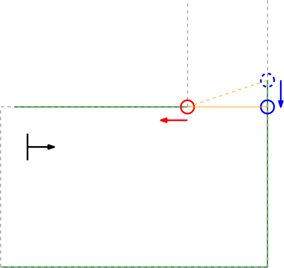
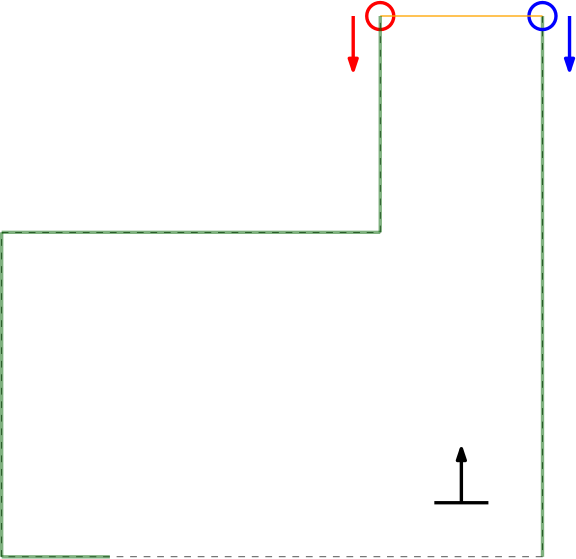
Within the context of the escape room challenge, either a one (from within the escape room) or two gaps (in front of or in the corridor) can be detected, as depicted in Figures \ref{} and \ref{}.
As can be seen in these Figures, dependent on PICO's orientation, gaps can be detected under an angle resulting in a false recognition of the corridor entry. To this end, the gap size is minimized by moving the points on the left and right side of the gap respectivily counterclockwise and clockwise. The result of this data processing is shown in the Figure \ref{} where the dotted orange line depicts the initial gap, and the straight orange line depicts the final gap. Here, the left (red) point is already optimal and the right (blue) point is optimized.

In this example of a possible situation, PICO is located straight in front of the corridor. In this case the gap cannot be optimized in the same way because moving either of the points increases the distance between the points (as they are not iterated at the same time). In the section xxx the script is expanded to deal with this scenario.