Firefly Eindhoven - Localization - Ultrawideband
System description
- Introduction
The goal of Firefly is to make an autonomous light show with drones. This show will involve three drones that fly in a nice-looking and coherent way. This is one example of what can be achieved when multiple drones work together to achieve something. There are multiple other applications that can be thought of, such as lifting objects, searching areas, etc. All these applications have something in common; they require to know their absolute position in some pre-defined area. For outside and low-precision objectives GPS can be used to solve this problem. However, the light show of Firefly will take place in an area of a few square meters. This means that an offset of more than roughly 15cm could cause major problems such as drones crashing into each other. The goal of the Ultra Wide Band (UWB) system is to provide this high accuracy positioning system.
So, how does this system work? The UWB system works with, so-called, beacons and tags. Beacons are hardware units located on predefined positions in the x,y,z-plane. The tags are hardware units on the agents (drones in this case). The beacons send messages to the tags by means of antennas; this means that the information in the message is encoded in an electromagnetic wave. The basic idea of the UWB system is that the messages include the timestamp, [math]\displaystyle{ t_1 }[/math], at which they were sent. The tag receives the message at a later timestamp, [math]\displaystyle{ t_2 }[/math], and saves that timestamp. Then the distance between the tag and the beacon can be found based on the difference between the two timestamps, [math]\displaystyle{ t_{\Delta} = t_2 - t_1 }[/math]. [math]\displaystyle{ t_{\Delta} }[/math] represents that it took the message to travel from the beacon to the tag. The speed at which the message travels is known, the speed of light, [math]\displaystyle{ c }[/math]. This means that the distance between the beacon and the tag, [math]\displaystyle{ \Delta x }[/math], can be found as [math]\displaystyle{ \Delta x = t_{\Delta}c }[/math]
For the light show, currently, a central supervisor is used that sends commands to the individual drones. However, this might be changed in the future to a more modular system, where every drone determines only for itself what control inputs it should give to itself. This is a very scalable solution and allows (if configured properly) an undefined amount of drones to work together. Although, it is not realistic to say that Firefly will be able to do this within the coming few months. However, we are developing this solution with a Avular, a company working on and with drones. They have plans to exploit this feature in the future. To realise this, all the computations should be done on the drone's hardware.
- The Algorithm
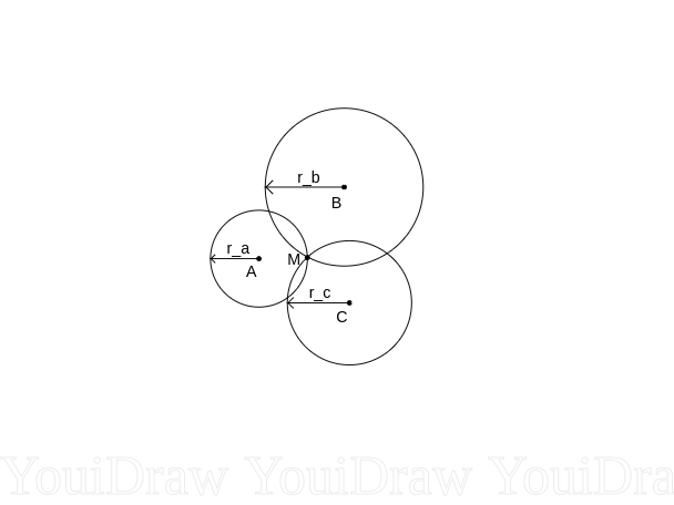
In this report, we will have a look at the 2D-case only for simplicity. The 3D-case should follow easily from the 2D case. In the introduction, it was explained how the distance between a tag and a beacon can be calculated. This means that we know that the tag has to be somewhere on a circle with radius [math]\displaystyle{ r_{\Delta} }[/math] around the beacon. From this follows that one beacon is not sufficient to get a unique solution for the location of the tag. However, if we combine three beacons, a unique position of the tag can be calculated. This is illustrated in figure the image below. The distances between the tag and beacon A, B and C were calculated, and indicated as [math]\displaystyle{ r\_a }[/math], [math]\displaystyle{ r\_b }[/math] and [math]\displaystyle{ r\_c }[/math], respectively, in the figure. The corresponding circles are drawn and we see that all the circles cross one point, point [math]\displaystyle{ M }[/math]. This point is the only solution that can be found that satisfies all the calculated distances.
Using some simple geometry, the following equations can be found
[math]\displaystyle{ (x-x_b)^2+(y-y_b)^2=\left(r\_a - r\_b + \sqrt{x^2+y^2}\right)^2, }[/math]
[math]\displaystyle{ (x-x_c)^2+(y-y_c)^2=\left(r\_a - r\_c +\sqrt{x^2+y^2}\right)^2, }[/math]
where [math]\displaystyle{ x }[/math] and [math]\displaystyle{ y }[/math] represent the x- and y-location of the tag, [math]\displaystyle{ x_b }[/math] and [math]\displaystyle{ y_b }[/math] represent the x- and y-location of beacon B, [math]\displaystyle{ x_c }[/math] and [math]\displaystyle{ y_c }[/math] define the x- and y-location of beacon C. The position of beacon A was defined as [math]\displaystyle{ x=0 }[/math] and [math]\displaystyle{ y=0 }[/math].
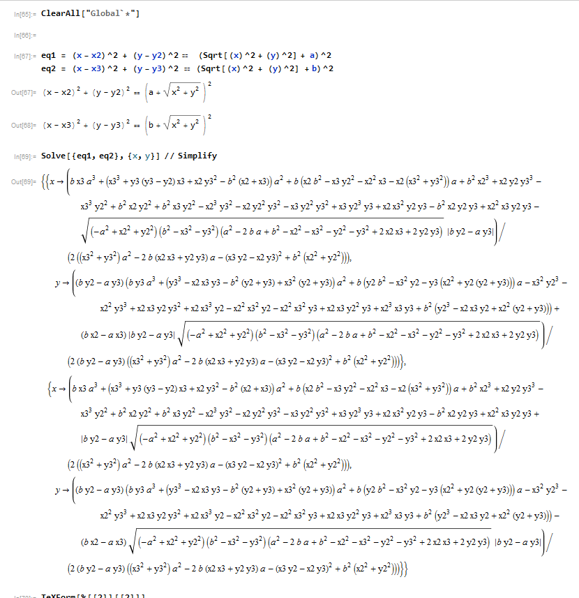
Note that all the variables required to solve this set of equations for [math]\displaystyle{ x }[/math] and [math]\displaystyle{ y }[/math] are available on the tag's side. This makes it possible to do all calculations on the drone itself, which allows for the decentralized computing of the locations of drones, if the algorithm to compute [math]\displaystyle{ x }[/math] and [math]\displaystyle{ y }[/math] is fast enough. The algorithm to calculate the solution to this appeared to be easier than expected. As shown in the section 'The Mathematics of the Algorithm', an exact solution can be found to this problem. The equation found by mathematica was further simplified and used to calculate the position.
- Accuracy
In the previous section, the algorithm to calculate the position of the tag was presented. However, a major assumption was not discussed in this calculation. It is assumed that the internal clocks of beacon A, B and C do not have an offset relative to each other and their clocks run exactly at a speed equivalent to that of real time. One might say that this should not be a problem, because the errors will be in the order of microseconds. However, since the distance calculation is based on the speed of light (which is huge), small errors in time do contribute a lot to the error in position estimation. As an example, if the clock would deviate by [math]\displaystyle{ 1 \mu s }[/math], the estimation of position will be off by approximately 300 meters. Obviously, this is an unacceptable error. To make the clocks as accurate as possible, it was decided to define one beacon as the master beacon. This beacon would make sure its clock runs its clock at a very accurate speed. The other beacons are slaves that get synchronized to the master clock. The master clock has to be synchronized to real time as accurate as possible. A crystal oscillator inside the beacon determines the exact speed of the internal clock. This crystal oscillator can be tuned to run faster or slower from simple commands in C. An external source will send a pulse every real second to the beacon, which will trigger an interrupt in the beacon. If the difference between the internal clock time between two consecutive interrupts is smaller than one seconds, the crystal will be adjusted such that it runs faster. If the difference is more than one second, it is adjusted to run slower. The crystal oscillator can be tuned and that improves accuracy, but the speed at which it runs is divided in 32 discrete states. One can imagine that the difference between two states might still make a rather big difference. In software, it can be further improved by take the difference between two consecutive interrupts and dividing this by the internal clock time that passed between those interrupts. We can achieve a double precision floating point accuracy on the discrepancy of the clock, assuming that the difference is linear. Avular asked us not to share information on the external source in public documents. On the slave beacon a very similar algorithm was implemented to the master beacon, but now the external source/clock is the master beacon. Also, the slave beacon compensates for the offset between the master beacon and the slave beacon.
- The mathematics of the Algorithm

