Embedded Motion Control 2018 Group 6
Group members
| Name: | Report name: | Student id: |
| Thomas Bosman | T.O.S.J. Bosman | 1280554 |
| Raaf Bartelds | R. Bartelds | add number |
| Bas Scheepens | S.J.M.C. Scheepens | 0778266 |
| Josja Geijsberts | J. Geijsberts | 0896965 |
| Rokesh Gajapathy | R. Gajapathy | 1036818 |
| Tim Albu | T. Albu | 19992109 |
| Marzieh Farahani | Marzieh Farahani | Tutor |
Initial Design
Requirements and Specifications
Use cases for Escape Room
1. Wall and Door Detection
2. Move with a certain profile
3. Navigate
Requirements for Escape Room
R1.1 The system shall detect walls without touching them
R1.2 The system shall detect the goal/door
R1.3 The system shall log and map the environment
R2.1 The system shall move slower than 0.5 m/s translational and 1.2 rad/s rotational
R2.2 The system shall not stay still for more than 30 seconds
R3.1 The system shall find the goal
R3.2 The system shall determine a path to the goal
R3.3 THe system shall navigate to the goal
R3.4 THe system shall not touch the walls
R3.5 The system shall complete the task within 5 minutes
Use cases for Hospital Room
(unfinished)
1. Mapping
2. Move with a certain profile
3. Orient itself
4. Navigate
Functions, Components and Interfaces
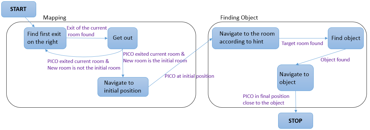
The softwarethat will be deployed on PICO can be categorized in four different components: perception, monitoring, plan and control. They exchange information through the world model, which stores all the data. Below, the functions of the four components are described. What these components will do is described for both the Escape Room Challenge (ERC) and the Hospital Challenge (HC).
Perception:
ERC:
Input: LRF-data
Use:
- Process (filter) the laser-readings
Interface to world model, perception will store:
- Distances to all near obstacles
HC:
Input: LRF-data, odometry
Use:
- Process both sensors with gmapping
- Process (filter) the laser-readings
Interface to world model, perception will store:
- processed data from the laser sensor, translated to a map (walls, rooms and exits)
- odometry data: encoders, control effort
Monitoring:
ERC: input: distances to objects process distances to determine situation: following wall, (near-)collision, entering corridor, escaped room result for world model: state of situation
HC: input: map, distances to objects process distances and map to determine situation: following path, (near-)collision, found object result for world model: state of situation
Plan:
ERC: input: state of situation determine next step: prevent collision, continue following wall, stop because finished result for world model: state of next step
HC: input: state of situation determine next step: goto new waypoint, continue following path, prevent collision, go back to start, stop because finished determine path to follow result for world model: state of next step
Control:
ERC: input: distances+angles to objects, state of next step determine setpoint angle and velocity of robot result for world model: setpoint angle and velocity of robot
HC: input: state of next step, path to follow determine setpoint angle and velocity of robot result for world model: setpoint angle and velocity of robot
