Embedded Motion Control 2012 Group 9
Group Members :
Ryvo Octaviano      0787614    r.octaviano@student.tue.nl
Weitian Kou         0786886    w.kou@student.tue.nl
Dennis Klein        0756547    d.klein@student.tue.nl
Harm Weerts         0748457    h.h.m.weerts@student.tue.nl
Thomas Meerwaldt    0660393    t.t.meerwaldt@student.tue.nl
Objective
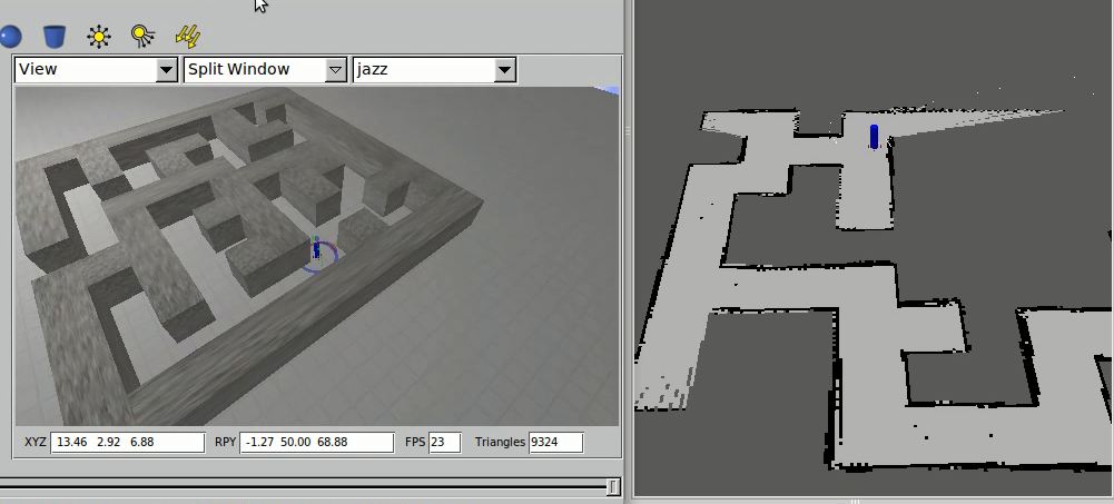
The Jazz robot find his way out of a maze in the shortest amount of time
Requirement
The Jazz robot refrains from colliding with the walls in the maze
The Jazz robot detects arrow (pointers) to choose moving to the left or to the right
Planning
An intermediate review will be held on June 4th, during the corridor competition
The final contest will be held some day between June 25th and July 6
Progress
Week 1
Make a group, find book & literature
Week 2
Installation :
1st laptop :
Ubuntu 10.04 (had an error in wireless connection : solved)
ROS Electric
Eclipse
Environmental setup
Learning :
C++ programming (http://www.cplusplus.com/doc/tutorial)
Chapter 11
Week 3
Installation :
SVN (Got the username & password on 8th May)
Learning :
ROS (http://www.ros.org/wiki/ROS/Tutorials)
Jazz Simulator (http://cstwiki.wtb.tue.nl/index.php?title=Jazz_Simulator)
To DO :
end of week 3
Finish setup for all computers
3 computers will use Ubuntu 11.10 and 1 computer uses Xubuntu 12.04
Week 4
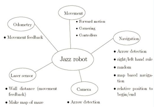
We did a brainstorm session on what functions we should make in the software, the result is below.
Week 5
We made a rudimentary software map and started developing two branches of software based on different ideas. The software map will be discussed and revised in light of the results of the software that was written early in week 6. The group members responsible for the lecture started reading/researching chapter 11.
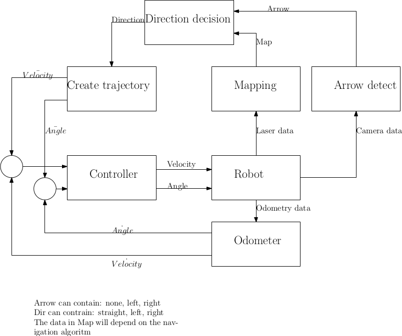
We decided to work on two branches of software, developing different ideas, in parallel. The first branch is based on the software map above. We started writing two nodes, one to process and publish laser data and one controller node to calculate and follow a trajectory. The former node reads laser data from the /scan topic and processes this to detect whether the robot is driving straight in a corner, detect and transmit corner coordinates and provide collision warnings. The second node is the controlling, which uses odometry data to provide input coordinates (i.e. a trajectory) for the robot to follow. The controller implemented is a PID controller, which is still to be tuned. The I and D actions might not be used/necessary in the end. The controller node will also use the laser data provided by the laser data node to be able to plan the trajectory for the robot. A decision algorithm (i.e. go left or right) is still to be developed.
Implementation So Far & Decision We Made
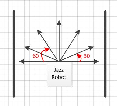
We are using 7 laser points with variety degrees as shown below :
1. The 0 is used for detecting the distance between the robot and the wall in front of the robot, it is also used for anti collision
2. The -90 and 90 are used to make the position of the robot looking forward and keep the distance between the robot and side wall
3. The -30, -60, 60, and 30 are used to detect the position of the free way (left side or right side)
2. Robot Movement
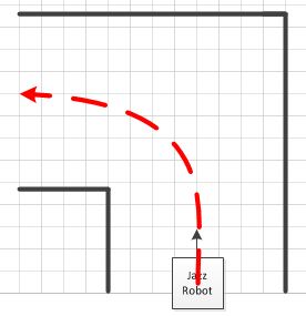
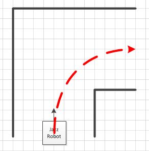
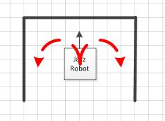
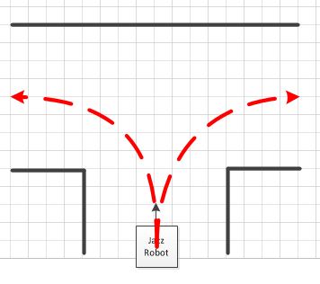
we designed the movement of the robot as show in the picture below. We want to make the robot turn the corner like one-fourth of circle, so it will cut the time because it has shorter path than turn the corner with 90 degrees movement
a. Turn Left or Right
b. Turn T connection
Because we have not already implemented the camera vision to help robot navigation, the movement of the robot either turn to right or left depends on the wall follower algorithm. If Righ Hand Rule activated, so the robot will go to right and vice versa.
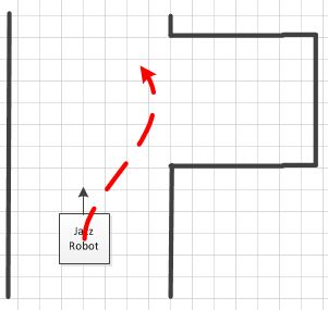
c. Dead end
d. Avoid Dead end
The robot we will avoid dead end
3. Building map with Laser & Odometry
The map is used to give information where the current location of the robot is. For future development this map also can be used for implementing Tremaux's Algorithm (http://www.youtube.com/watch?v=6OzpKm4te-E). We are trying to do that, so our robot would not go to the same place twice.
4. Algorithm
There are a lot of algorithms to solve the maze problem (http://en.wikipedia.org/wiki/Maze_solving_algorithm) , the simplest basic idea that can be implemented easily is using Wall follower (Right Hand Rule of Left Hand Rule). We are trying to find the best algorithm that give us the shortest time to find exit
a. We have already implemented the Wall follower algorithm
This would be fine except for two things.
1. Firstly, you may have to visit almost the entire maze before you find the exit so this can be a very slow technique.
2. Secondly, the maze may have islands in it. Unless all the walls are eventually connected to the outside, you may wander around forever without reaching the exit.
http://www.robotix.in/rbtx09/tutorials/m4d4
To solve this problem, we can use Camera for navigation
b. We also have already implemented the random mouse algorithm
But to make it more intelligent we want to add memory (Modified FloodFill), so the robot won't go same place twice (http://www.youtube.com/watch?v=DVB_twrqlu8)
As the cells are mapped with the numbers as shown in the figure, at each cell the robot is expected to take three decisions.
1. Move to cell which it has gone to least
2. Move to the cell that has minimum cell value
3. If possible the robot must try to go straight.
http://www.robotix.in/rbtx09/tutorials/m4d4
VIDEO DOCUMENTATION
1. First Trial Mouse Algorithm (http://www.youtube.com/watch?v=9xynPzQU7Q8&feature=youtu.be)
2. First Trial Right Hand Rule Algorithm (http://www.youtube.com/watch?v=_c31Wct0tPI&feature=youtu.be)
Choice between 2 algoritms
1st Algoritm (complex):
- Make Gmap with odometry and laser
- Detect arrow
- Decide left/right/straight (Navigation algoritm)
- Create trajectory (As in a tracking control problem)
- Follow trajectory (Tracking control problem)
- Collision detection
2nd Algoritm (easy):
- Follow right wall
- Detect dead ends
- Make nice left turns
- Detect arrow
Comparision:
- The 1st algoritm is smarter
- The 2nd algoritm is easier to implement
- The 2nd algoritm costs less time to implement
- The robustness of the 1st algoritm is unknown
- The 2nd algoritm will probably work most of the time
We choose the 2nd algoritm
Arrow Detection
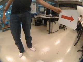
At least two steps are needed for arrow detection: segment red arrow from complex background and detect the direction. More details are as follows, and picture frame0008.jpg from the video is shown as an example.
Segment red arrow
- Segment red part from original picture. Since pictures in OpenCV can be easily represented in RGB and HSV and converted between each other, we try two filtering methods based on RGB and HSV respectively and then compare the results to choose one with better performance.
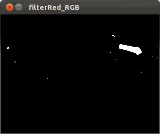
With RGB colorspace, three color channels can be splitted by cvSplit() function in OpenCV. Because white are combination of red, blue and green, white part is also represented in three single channels. Thus we approximate that [math]\displaystyle{ ''realRed = cRed - cBlue - cGreen'' }[/math] to remove the influence of white color. After that, use cvThreshold() to make picture binary and filter dark points below a setting threshold.
 cvSplit(img, cBlue, cGreen, cRed, NULL);
 cvAdd(cBlue, cGreen, cGreen);
 cvSub(cRed, cGreen, cRed);
 cvThreshold(cRed, cRed,REDBOUND,255, CV_THRESH_BINARY);
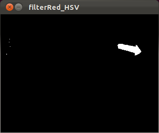
To work with HSV colorspace, first use function cvCvtColor() to convert BGR to HSV. And then select interested red part by using cvInRangeS() and cvOr(). Here two hues ranges are used because HSV colorspace is actually a circle.
 cvInRangeS(imgHSV, Low1, High1, imageArrowPixels1);
 cvInRangeS(imgHSV, Low2, High2, imageArrowPixels2);
 cvOr(imageArrowPixels1, imageArrowPixels2, imageArrowPixels);
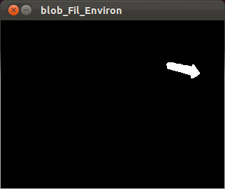
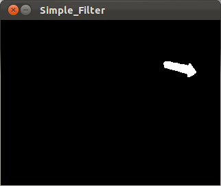
When we set REDBOUND in RGB method to 10 and set boundaries in HSV method to a relative large range, the segmentation result is shown below. The left one is from RGB and right from HSV and with less noise (small areas). After trying all the samples from the video, we find that the REDBOUND that can segment all these arrows always brought more noise than HSV method. Thus we choose the second method.
- Remove all the environment noise.
In order to get rid of the influence from more complex environment, we´d better remove all the environment noise. In that case, we find a very useful blob extraction library to OpenCV - cvBlobsLib. It provides functions to manipulate, filter and extract results from the extracted blobs. We can use blobs.Filter to remove blobs with small areas, and then select the biggest blob as the arrow, fill it with white color. In this way only one blob is left in the picture, and when there is no other large red noise from the environment, we can surely assume the left area is the arrow. As can be seen blow, this filter does very well to remove all the noise.
But we met problem when we implemented blob filter to ros, because cvBlobsLib is not a internal library of OpenCV. Since we don´t want to spend to much time to fix this problem, we tried a simple filter method as a substitution. In this method, cvErode() and cvDilate() are used to help remove small number of pixels. Because our HSV filter in the first step is good enough (only quite small pieces are left), this simple further filter also works well as the following picture shows.
Detect direction
At first we considered finding the corners of arrow. However, because we use relatively strict filter above, the final arrow we get is not very accurate, i.e. no sharp angle. We cannot get correct numbers of corners in this case. And from the direct view that the arrow head should be ¨heavier¨ than arrow tail, we decided to use areas to detect direction. So the problem becomes to find a proper dividing line in the arrow and compare areas.
- Find dividing line.
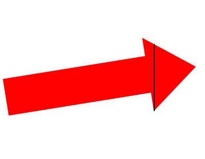
In this part, we obtain the approximate position of arrow head by calculating the position of maximum vertical line, because we find that as long as the arrow plane is approximately parallel to the camera, then the maximum vertical line is always on the arrow head side.
- Calculate areas of left and right parts. get the direction by comparing two area values.
In order to separate two parts, we use Region of Interest (ROI) in OpenCV, and use cvMoments() to easily calculate areas. Since the dividing line stays at arrow head, then the smaller area represents arrow direction. Here to get more accurate result, we filter again the arrows with small areas, that means arrows can only be detected when it is large enough in Jazz´s eyes.
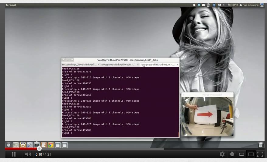
We test this code for all the samples as well as the video we made by ourselves, the result goes quite well, but there would still be wrong detection when Jazz move too sharply. So an accurate controller is needed to move Jazz smoothly.
Video of testing
After the corridor competition
The corridor competition did not go well. The main problem was taking corners and driving straight did not go well either.
The problem might be caused by communication delay, but probably by the robustness of the controller. The solution for this is improving the controller. The current controller is based on a nested if-then structure. The new controller is based on the distance to the middle of the corridor and the angle with the wall.
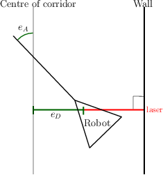
As can be seen in the picture, the shortest distance measured by a laser is allways perpendicular to the wall, and the [math]\displaystyle{ e_D }[/math] can be calculated from this. The [math]\displaystyle{ e_A }[/math] can also be calculated from this measurement. We will use the following control law:
[math]\displaystyle{ Velocity = K_1 cos(e_A) }[/math]
[math]\displaystyle{ Angular = K_2 e_A + K_3 e_D }[/math]
The velocity will be 0 when the robot faces the wall, and it will be maximum when the robot is straight. The angular velocity makes the robot steer towards the middle when it is at the side of the corridor. When the robot is in the middle of the corridor it will steer the robot straight. This controller is currently working in the simulator but it needs proper testing on the real robot. We don't know exactly how robust the turning of corners is, we might need to add a simple 90 degree turning algoritm. Another problem could be the noise as we currently have no filter for measurement noise, a Kalman filter could be usefull. Changing the controller from proporional to a lead/lag type could improve performance when necessary.
First real test results
The new wall following algoritm works well at a maximum speed of 0.05. With a speed of 0.1 it is unstable, possibly caused by the lag of the wifi connection. There are 2 other small issues: The robot starts to stray when the corridor width varies a little, this is caused by the algoritm. The robot tries to stay at 0.5m from both walls, when the width is less than 1m it will chose between the walls and show undesirable behaviour. A solution would be to either decrease the distance to the wall, or add a dead zone. The second problem is that the robot does not stop when facing the wall, and close to it. It an be fixed by not moving when the forward lasers detect an object in front of the robot.
The wall following algoritm will also take corners when some laser data is ignored. This means that the robot will only navigate based on the left side lasers when turning left (it only sees the left wall), and vice versa. During testing we noticed that the robot makes the corner a bit too big and corrects itself afterwards. This could become a problem at higher speeds, a solution could be to shorten the distance to the wall (on the inside of the corner).
A video of the trial run .
