Mobile Robot Control 2020 Group 7: Difference between revisions
| Line 99: | Line 99: | ||
''' Initialization ''' | ''' Initialization ''' | ||
This is the first phase of the robot as soon as the software is run. All the inputs and outputs of the robot are initialized and checked, during this phase. Moreover, all the required variables in the software are set to their correct values. At the end of the initialization phase the software is set and ready to perform the desired tasks. The first task of the robot is to find the wall and align with it. | This is the first phase of the robot as soon as the software is run. All the inputs and outputs of the robot are initialized and checked, during this phase. Moreover, all the required variables in the software are set to their correct values. At the end of the initialization phase the software is set and ready to perform the desired tasks. The first task of the robot is to find the wall and align with it. | ||
Revision as of 11:29, 25 May 2020
Group Members
| Name | Student Number | |
|---|---|---|
| 1 | Mick Decates | 0957870 |
| 2 | Steven Eisinger | 1449273 |
| 3 | Gerben Erens | 0997906 |
| 4 | Roohi Jain | 1475061 |
| 5 | Mengqi Wang | 1449435 |
| 6 | Goos Wetzer | 0902160 |
Introduction
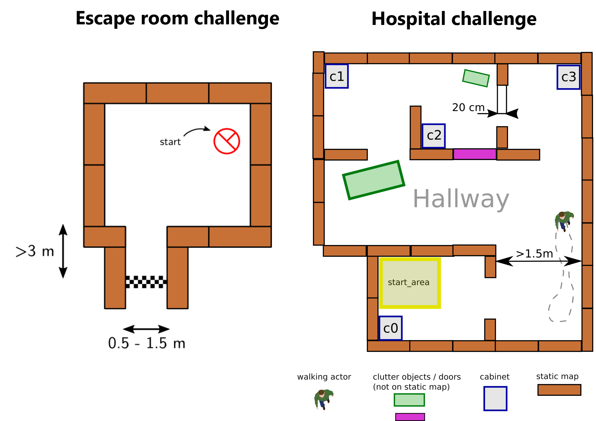
Welcome to the wiki of group 7 of the 2020 Mobile Robot Control Control course. During this course the group designed and implemented their own software which allows a PICO robot to complete two different challenges autonomously. The first challenge is the "Escape room challenge" where the PICO robot must drive out of the room from a given initial position inside the room. In the second challenge called the "Hospital challenge" the goal is to visit an unknown number of cabinets in a specific order, placed in different rooms. For both challenges the group designed one generic software structure that is capable of completing both challenges without changing the complete structure of the program. The example maps of both challenges are shown in Figure 1 to give a general idea about the challenges. The full details of both challenges are given on the general wiki page of the 2020 Mobile Robot Control course (link).
Escape room challenge
The main goal of the challenge was to exit the room as fast as possible, given an arbitrary initial position and orientation of PICO. The robot will encounter various constraints such as the length of the finish line from the door, width of the hall way, time constraints and accuracy. The PICO robot was first placed in a rectangular room with unknown dimensions and one door/opening towards the corridor. The corridor was perpendicular to the room with an opening on its far end as well. The initial position and orientation of the PICO robot was completely arbitrary. PICO was supposed to cross the finish line placed at a distance greater than or equal to 3 metres from the door of the corridor. The walls of the room were also not straight which posed a challenge during the mapping of the room from the laser data. The challenge is discussed in much detail about the algorithms used, implementation, program flow and results of the challenge in the following sections.
Hospital challenge
The main goal of this challenge was to visit the cabinets in a particular order given by the user as fast as possible. The global map consisting of rooms and cabinets and the starting room of PICO were mentioned beforehand. The hospital challenge contained multiple rooms with doors which can be open or closed. It tested the ability of PICO to avoid static/dynamic objects and plan an optimal path dynamically. The static objects included clutter objects/doors and the dynamic objects included human beings moving in the room while PICO was performing its task which were not specified on the given global map. Lastly, PICO was asked to visit the list of cabinets to visit in a specified order given by the user before the start of the challenge. The challenge is discussed in much detail in the following sections. The algorithms used are explained, how they are implemented is shown, the program flow is discussed, and the results of the challenge are told.
ESCAPE ROOM CHALLENGE
Requirements & Specifications
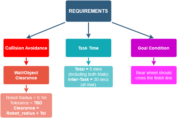
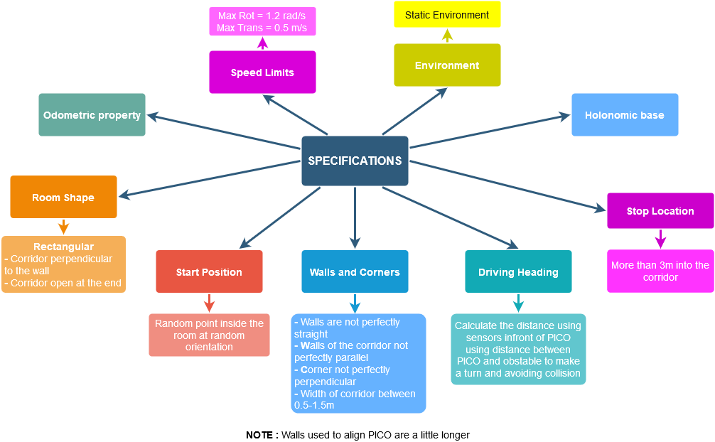
The requirements and specifications for the challenge are shown in figure. The primary requirement is safety that we need to fulfill by avoiding collision. All other requirements shall be treated equally.
Functions
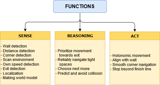
Once the robot is deployed in the room, it should sense around the room and try to find the exit corridor. If it cannot find the corridor, it should move around the room in an attempt to find it. Once the corridor is found it should position itself in front of the corridor and proceed through it until crossing the finish line.The functions that the robot needs to perform these tasks are described in Figure 2.1. These functions are divided into three main components: Sense, which allows the robot to perceive and quantify its world; Reasoning, where the robot makes a decision based on its perception; and Act, which determines what action the robot performs based on its reasoning information.
Hardware Components
Sensors - Laser Range Finder
The laser range finder measures the distance from the robot to the closest obstacle for a range of angles around the direction the robot is facing. The sensor data is stored in a structure called LaserData, which is described in table 3.1. There are 1000 measurements in total.
| Property | Description |
|---|---|
| range_max | The maximum range that can be measured is 10 meters |
| range_min | The minimum range that can be measured is 0.01 meters |
| angle_max | 2 radians from the direction straight ahead |
| angle_min | -2 radians from the direction straight ahead |
| angle_increment | Each angle is 0.004004 radians away from the next one |
| timestamp | Timestamp of the measurement in UNIX |
Sensors - Odometry
The odometry data measures the distance the robot has traveled in all 3 degrees of freedom in the horizontal plane.This data is obtained through encoders on the wheels of the holonomic base, which are stored in a structure called OdometryData, described in table 3.2. Small errors could accumulate over time due to measurement errors and wheel slip. To combat this, the positional data of the robot will be updated using the difference between the current and previous odometry measurement. This data is then corrected with the use of the world model and the data obtained from the laser range finder.
| Property | Description |
|---|---|
| x | distance travelled in horizonal direction since start of measurement |
| y | distance travelled in vertical direction since start of measurement |
| a | angle rotation since start of measurement |
| timestamp | Timestamp of the measurement in UNIX |
Actuators
The robot is built on a holonomic base, which means that it has three degrees of freedom in its horizontal plane: twotranslational, and one rotational. The robot is able to move in these ways using its omni-directional wheels, which are placed in a triangular formation on the base. Besides being able to provide a force in the driving direction,unlike normal wheels, the omni-directional wheels also do not constrain movement in the direction orthogonal tothe driving direction. Because of this, the robot is able to move with a given max velocity in all possible directions of the horizontal plane.
Software Infrastructure
The software will be divided into components, which are connected through certain interfaces. Major components are seen in Figure 5, and their interfaces are specified with the arrows. Perception is the component where the PICO uses sensor data from LaserData and OdometryData to get an idea of it’s current location. This data is interfaced with the World Model, which stores map and localization data, including the exit location once found. The Planning component takes care of decision making and control planning, including path finding and obstacle avoidance. The actuation component will actuate the holonomic base in order to carry out the movement plan.

Implementation
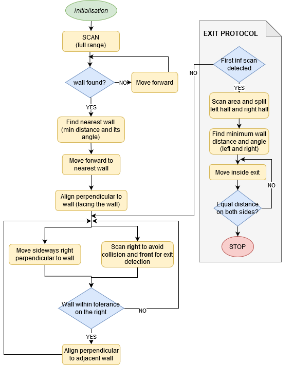
The overall software behavior is divided in five clearly distinguished phases. During each phase all actions lead to one specific goal and when that goal is reached, a transition is made towards the next phase. The overall program logic can be seen in Figure 6.
Initialization
This is the first phase of the robot as soon as the software is run. All the inputs and outputs of the robot are initialized and checked, during this phase. Moreover, all the required variables in the software are set to their correct values. At the end of the initialization phase the software is set and ready to perform the desired tasks. The first task of the robot is to find the wall and align with it.
Find wall and Align with wall
@Goos add your part here
Follow the wall and lookout for corners
@Roohi add your part here
Exit detection
@Mick add your part here
Exit Alignment
@Gerben add your part here
Move in corridor
@Mengqi add your part here
Execution
HOSPITAL CHALLENGE
Requirements and Specifications

