Embedded Motion Control 2019 Group 2: Difference between revisions
| Line 226: | Line 226: | ||
= Code snippets = | = Code snippets = | ||
* [https://gitlab.tue.nl/EMC2019/group2/snippets/126 Main] | |||
* [https://gitlab.tue.nl/EMC2019/group2/snippets/127 Fit lines on laserdata] | * [https://gitlab.tue.nl/EMC2019/group2/snippets/127 Fit lines on laserdata] | ||
Revision as of 16:24, 15 June 2019
Group members
- 1. Bob Clephas | 1271431
- 2. Tom van de laar | 1265938
- 3. Job Meijer | 1268155
- 4. Marcel van Wensveen | 1253085
- 5. Anish Kumar Govada | 1348701
Intro
TODO: Anish
Design document
To complete the two assignments for the course “Embedded motion control” specific software must be written. In this design document the global architecture of the software is explained, and the given constraints and hardware is listed. This document is a first draft and will be updated during the project. The first version can be found here.
Requirements and specifications
The requirements and related specifications are listed in the following table. The listed specifications are required for the final assignment and the escape room challenge.
Components and functions
The components and their functions are split in software components and hardware components.
Software components
Hardware components and their general functionalities
Environment
The environments for both assignments will meet the following specifications:
Escape room challenge
- Rectangular room, unknown dimensions. One opening with a corridor.
- Starting point and orientation is random, but equal for all groups.
- Opening will be perpendicular to the room.
- Far end of the corridor will be open.
- Wall will not be perfectly straight, walls of the corridor will not be perfectly parallel.
- Finish line is at least 3 meters in the corridor, walls of the corridor will be a little bit longer.
Final challenge
- Walls will be perpendicular to each other
- Global map is provided before competition
- Location of cabinets is provided in global map
- Static elements, not showed in global map, will be in the area
- Dynamic (moving) elements will be in the area
- Objects can have a random orientation
- Multiple rooms with doors
- Doors are time-varying opening an closing
- list of "To-be-visited" cabinets is provided just before competition
General software architecture and interface
TODO: Anish
The overall software is split in several building blocks:
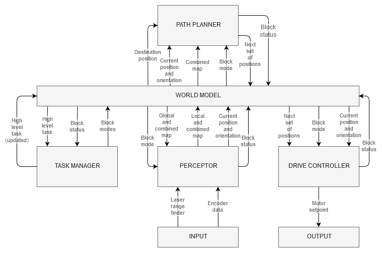
Overall program flow
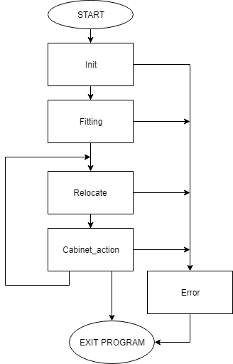
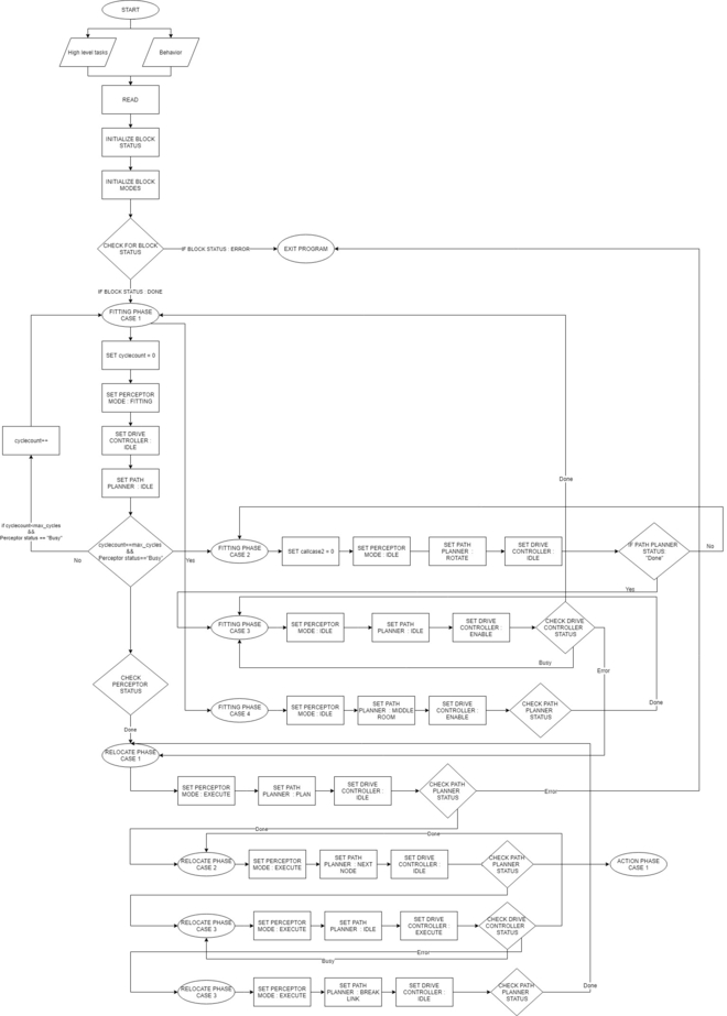
The overall program is divided in 5 phases. During a phase all actions lead to one specific goal. When the goal is reached, a transition is made towards a new phase. Within a phase it is possible to have multiple cases. Each iteration of the program it is evaluated to what phase and case the program should move. It is also possible to stay in a specific phase and case for longer than one program iteration, however, in most situations this is not needed. Every case has a specific block mode for each software block and the transitions between cases and phases is based on the blockstatusses of all blocks.
Phases flowchart
In figure 2 the overall structure with the phases is shown. The different phases have the following goals:
Init phase
The init phase focuses on the initialisation of the program. This phase has one case and the flowchart of this phase is shown in figure 3.
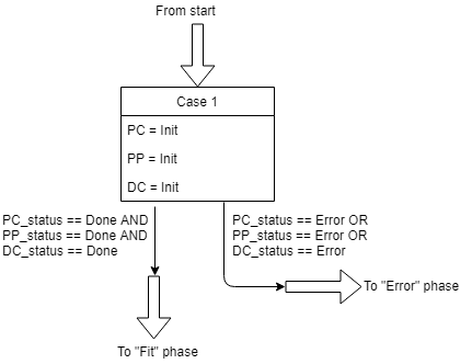
During the init phase the following actions are executed:
Fitting phase
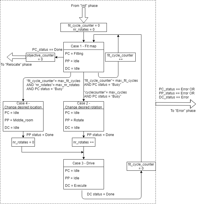
In the fitting phase the goal is to locate the robot relative to the given global map. This fitting is done in the perceptor by checking the laserdata, creating a local map and try to find a best fit between the local and global map. If this fit is successful the location of the robot is known and all new laser information can be used to update the location of the robot.
Relocate phase
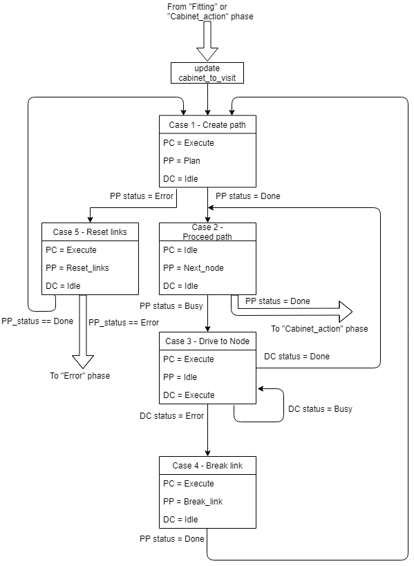
In the "Relocate" phase the goal is to drive the robot to the next cabinet. The driving involves the path planning, actuating the drivetrain of the robot and avoiding obstacles. During the driving the perceptor keeps updating the world map and keeps adding objects to the map is necessary. Also the fitting will be improved once more laserdata is obtained.
In figure 5 the overall flowchart is shown of the relocate phase. This phase contains the following cases:
Cabinet_action phase

During the cabinet action phase the robot can interact with the cabinet.
The required interaction is specified in the competition and is consisting of taking a snapshot of the current laserdata and play a sound.
The flowchart of this phase is shown in figure 6.
Error phase
The error phase is only visited if something unrecoverably went wrong in the program, e.g. a required file is missing. In this phase the output of the drive motors is set to zero and the error is displayed to the user. Then the program is terminated
Software blocks
Task manager
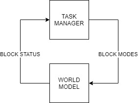
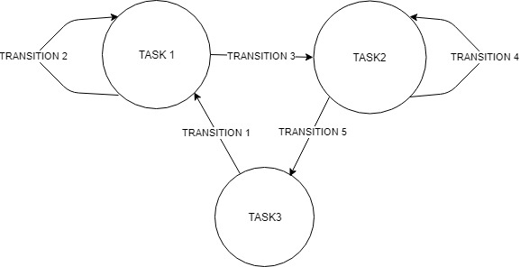
The task manager functions as a finite state machine which switches between different tasks/states. Based on the current phase, current case, current blockstatusses and optional some counters it determines the next operation phase and case. It then sets the corresponding blockmodes of the perceptor, path planner and drive controller for the upcoming execution. It communicates with the other blocks via the World model.
Since the "Escape room challenge" and the "Hospital competition" require a complete different approach in terms of cooperation between the blocks, the task planner is completely rewritten for both challenges.
ESCAPE ROOM CHALLENGE
BASIC BLOCK DIAGRAM :
INITIALIZATION:
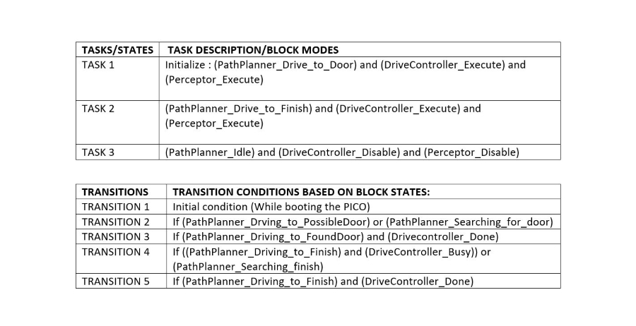
The path planner is given a command “Drive_to_door” while the drive controller and the preceptor are given a command “Execute” as a part of the initialization process.
EXECUTION:
The high-level tasks “Drive_to_door”, “Drive_to_exit”, “Execute”, “Idle” and “Disable” were given to appropriate blocks as shown below:
KEY:
HOSPITAL ROOM CHALLENGE :
FLOW CHART :
The function description can be found here : File:TASK MANAGERfin.pdf
Perceptor
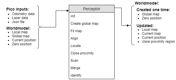
The perceptor receives all of the incoming data from the pico robot and converts the data to useful data for the worldmodel. The incoming data exists of odometry data obtained by the wheel encoders of the pico robot. The laserdata obtained by the laser scanners. A Json file containing the global map and location of the cabinets, this file is provided a week before the hospital challenge. Moreover, the output of the perceptor to the world model consists of the global map, a local map, a combined map, the current/zero position and a close proximity region. The incoming data is handled within the perceptor by the following functions. A detailed description on what each function does in the preceptor and more information about the data flow can be found here.
The inputs and outputs of the perceptor are shown in the following figure:
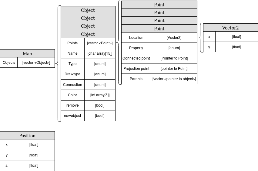
The data used in the perceptor:
Path planner
The path planner determines the path for the PICO robot based on the combined map, the current location and the desired location. The planned path is a set of positions that the PICO robot is going to drive towards, this set is called the ‘next set of positions’. This next set of positions is saved in the world model and used by the task manager to send destination points to the drive controller.
If the path planner is idle, it is waiting for the task manager to start planning. Once the path planner is planning the path from the position of the PICO robot towards a given destination, the following things happen. First the map is gridded, creating all possible locations that the PICO robot is able to move towards. Then different paths are planned, for example through different doors. After that the most optimal path is planned and sent to the world model as next set of positions. When the PICO robot is following the path, the path planner checks if no unexpected objects are interfering with the planned trajectory.
The inputs, functions and outputs of the path planner are as follows:
A detailed description can be found here.
Drive controller
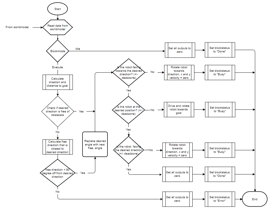
The drive Controller ensures that the pico robot drives to the desired location. It calculate the distance and direction to the desired location, relative to the current location. It checks if this direction is free of obstacles, if not it calculates an alternative direction that brings the pico robot closer to the desired destination. Finally it uses three PI controllers, one for each axis (rotational, X and Y) to calculate the desired speed for each axis and this is send to the pico-robot with the build-in function.
Inputs and outputs
Flow chart
The full details of the Drive Controller, including function descriptions can be found in the Drive Controller functionality description document found here.
Visualisation
Challenges
Escape Room Challenge
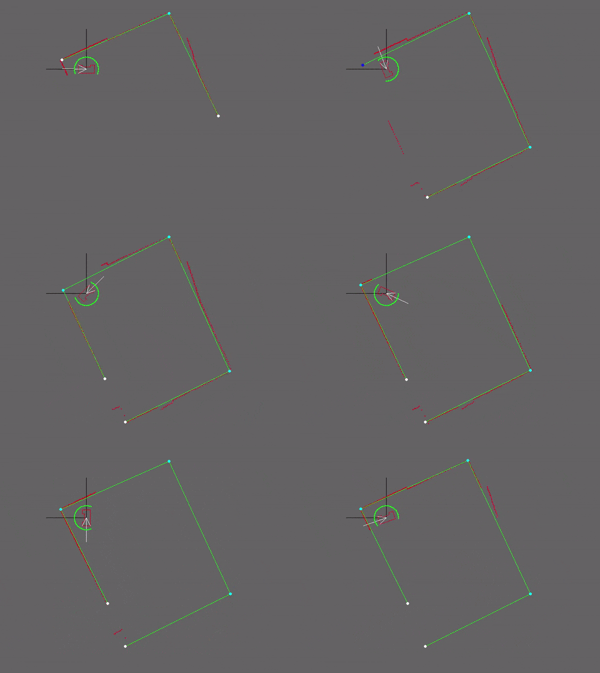
Our strategy for the escape room challenge was to use the software structure for the hospital challenge as much as possible. Therefore, the room is scanned from its initial position. From this location a local map of the room is created by the perceptor. Including, convex or concave corner points, doors and possible doors (if it is not fully certain the door is real). Based on this local map the task manager gives commands to the drive controller and path planner to position in front of the door. Once in front of the the possible door and verified as a real door the path planner sends the next position to the world model. Which is the end of the finish line in this case, which is detected by two lose ends of the walls. Also the robot is able to detect if there are objects in front of the robot to eventually avoid them.
Simulation and testing
Multiple possible maps where created and tested. In most of the cases the robot was able to escape the room. However, in some cases such as the room in the escape room challenge the robot could not escape. The cases were analyzed but there was enough time to implement these cases. Furthermore, the software was only partly tested with the real environment at the time of the escape room challenge. Each separate function worked, such as driving to destinations, making a local map with walls, doors and corner points, driving trough a hallway and avoiding obstacles.
What went good during the escape room challenge:
The robot was made robust, it could detect the walls even though a few walls were placed under a small angle and not straight next to each other. Furthermore, the graphical feedback in from of a local map was implemented on the “face” of the Pico. The Pico even drove to a possible door when later realizing this was not a door.
Improvements for the escape room challenge:
Doors can only be detected if it consists of convex corners, or two loose ends facing each other. In the challenge it was therefore not able to detect a possible door. The loose ends were not facing each other as can be seen in the gif below. Furthermore, there was not back up strategy when no doors where found, other then scanning the map again. Pico should have re-positioned itself somewhere else in the room or the pico could have followed a wall. However, we are not intending to use a wall follower in the hospital challenge. Therefore, this does not correspond with our chosen strategy. Another point that can be improved is creating the walls. For now walls can only be detected with a minimal number of laser points. Therefore, in the challenge it was not able to detect the small wall next to the corridor straight away. This was done to create a robust map but therefore also excluded some essential parts of the map.
In the simulation environment the map is recreated including the roughly placed walls. As expected in this simulation of the escape room the pico did not succeed to find the exit, the reasons are explained above.
Hospital Competition
The software for the hospital competition is an improved version of the software used during the escape room challenge. The same structure with blocks is used and as much as possible software is reused and adjusted if necessary. Major changes are done to the path planner and task manager since the hospital challenge is much more complex for those two blocks compared to the escape room challenge.
