Drone Referee - MSD 2018/9: Difference between revisions
No edit summary |
No edit summary |
||
| Line 26: | Line 26: | ||
===MSL/Ball-Following 2D CAFCR=== | ===MSL/Ball-Following 2D CAFCR=== | ||
===MSL/Ball-Following 2D | ===MSL/Ball-Following 2D use cases=== | ||
===MSL/Ball-Following 2D | ===MSL/Ball-Following 2D context diagrams=== | ||
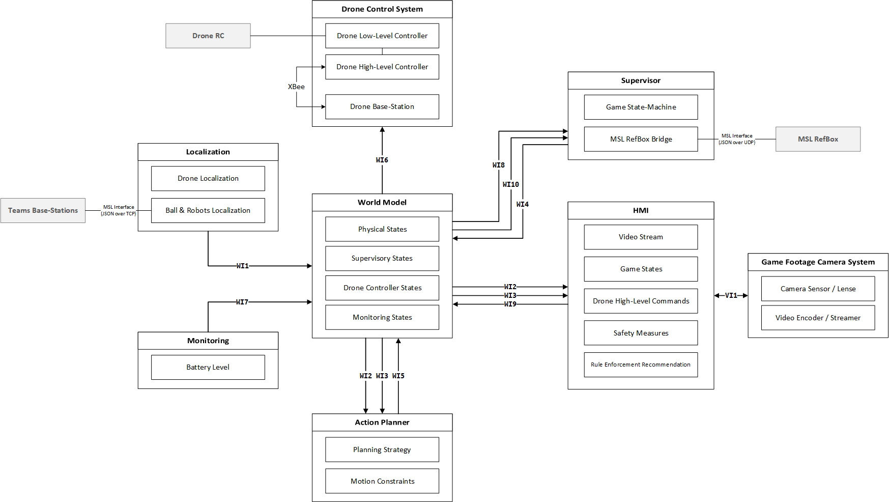
[[File:MSL-Context-Diagram.png]] | [[File:MSL-Context-Diagram.png]] | ||
| Line 37: | Line 37: | ||
====World Model==== | ====World Model==== | ||
====Camera | ====Camera footage system and HMI==== | ||
====Supervisor==== | ====Supervisor==== | ||
====Action | ====Action planner==== | ||
====Localization | ====Localization systems==== | ||
==MSL/Ball-Following Gimbal == | ==MSL/Ball-Following Gimbal == | ||
| Line 49: | Line 49: | ||
===MSL/Ball-Following Gimbal CAFCR=== | ===MSL/Ball-Following Gimbal CAFCR=== | ||
===MSL/Ball-Following Gimbal | ===MSL/Ball-Following Gimbal use case=== | ||
===MSL/Ball-Following Gimbal | ===MSL/Ball-Following Gimbal context diagrams=== | ||
=Project Management= | =Project Management= | ||
| Line 57: | Line 57: | ||
==Introduction== | ==Introduction== | ||
==Project | ==Project management plan== | ||
==Communication | ==Communication management plan== | ||
==Quality | ==Quality management plan== | ||
==Test management | ==Test management plan== | ||
==Risk | ==Risk analysis== | ||
=Simulation= | =Simulation= | ||
| Line 71: | Line 71: | ||
==Introduction== | ==Introduction== | ||
==Architecture | ==Architecture constraints== | ||
==System | ==System description== | ||
===Interface (I/O) | ===Interface (I/O) descriptions=== | ||
===Component | ===Component descriptions=== | ||
* 2-D | * 2-D | ||
| Line 83: | Line 83: | ||
*Gimbal | *Gimbal | ||
==Design | ==Design choices== | ||
==Technology== | ==Technology== | ||
| Line 95: | Line 95: | ||
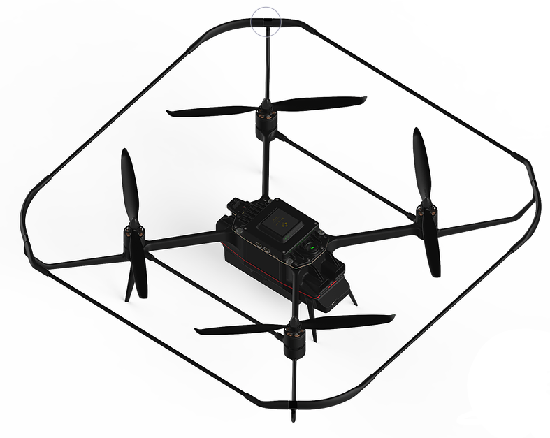
The drone is the main hardware subsystem of the RAS. This subsystem includes sensors, microcontroller, communication ports and mechanical components. The drone used in this project, is the last version of Avular curiosity drone provided by Avular company. The drone can be programmed by means of Matlab Simulink. All the other subsystems must eventually be implemented on the drone to achieve the final goal of game refereeing. | The drone is the main hardware subsystem of the RAS. This subsystem includes sensors, microcontroller, communication ports and mechanical components. The drone used in this project, is the last version of Avular curiosity drone provided by Avular company. The drone can be programmed by means of Matlab Simulink. All the other subsystems must eventually be implemented on the drone to achieve the final goal of game refereeing. | ||
===Architecture | ===Architecture constraints=== | ||
'''*RAS:''' | '''*RAS:''' | ||
| Line 113: | Line 113: | ||
The drone must be able to fly for 5+2 minutes and show the battery level all the time. | The drone must be able to fly for 5+2 minutes and show the battery level all the time. | ||
===System | ===System description=== | ||
The drone is the main hardware subsystem of drone referee system which consists of different components and subsystems itself. The main task of the drone is to receive commands in real time from a remote computing module (usually a PC) and follow the action required from action planner while carrying the footage camera. For this need,the main challenge is programming the drone and setting the wireless connection for sending wireless data to the microcontroller present on the drone. There are three main computation modules called “Low-Level Module”, “High-Level Module” and “Compute Module”. Each one of the Low-Level, High-Level, and Compute Modules is connected to a different set of sensors, actuators or communication devices. The idea is to use Low-Level Module for calculations related to flight stabilization and monitoring the current status of the drone, and use the High-Level Module for other high-level calculations (such as path planning or position control of the drone) which can be different depending on the project requirements. For projects that require intensive computations, the Compute Module can also be used in combination with both High-Level and Low-Level Modules. | The drone is the main hardware subsystem of drone referee system which consists of different components and subsystems itself. The main task of the drone is to receive commands in real time from a remote computing module (usually a PC) and follow the action required from action planner while carrying the footage camera. For this need,the main challenge is programming the drone and setting the wireless connection for sending wireless data to the microcontroller present on the drone. There are three main computation modules called “Low-Level Module”, “High-Level Module” and “Compute Module”. Each one of the Low-Level, High-Level, and Compute Modules is connected to a different set of sensors, actuators or communication devices. The idea is to use Low-Level Module for calculations related to flight stabilization and monitoring the current status of the drone, and use the High-Level Module for other high-level calculations (such as path planning or position control of the drone) which can be different depending on the project requirements. For projects that require intensive computations, the Compute Module can also be used in combination with both High-Level and Low-Level Modules. | ||
Each one of the High-Level and Low-Level Modules uses one 180MHz Cortex-M4 processor and the Compute Module is a Raspberry-Pi Compute Module 3. | Each one of the High-Level and Low-Level Modules uses one 180MHz Cortex-M4 processor and the Compute Module is a Raspberry-Pi Compute Module 3. | ||
===Design | ===Design choices=== | ||
===Subsystem | ===Subsystem results (demo) === | ||
==World | ==World model== | ||
==Camera | ==Camera footage system and HMI== | ||
==Supervisor== | ==Supervisor== | ||
==Action | ==Action planner== | ||
==Localization | ==Localization systems== | ||
=Demonstration= | =Demonstration= | ||
=Conclusion and | =Conclusion and recommendations= | ||
=Appendix= | =Appendix= | ||
Revision as of 14:19, 4 April 2019

Introduction
Architecture
In this part we introduce CAFCR and its role in building our architecture (RAS & MSL)
Introduction and overview
CAFCR
Referee aiding system
Referee aiding system (RAS)
RAS CAFCR
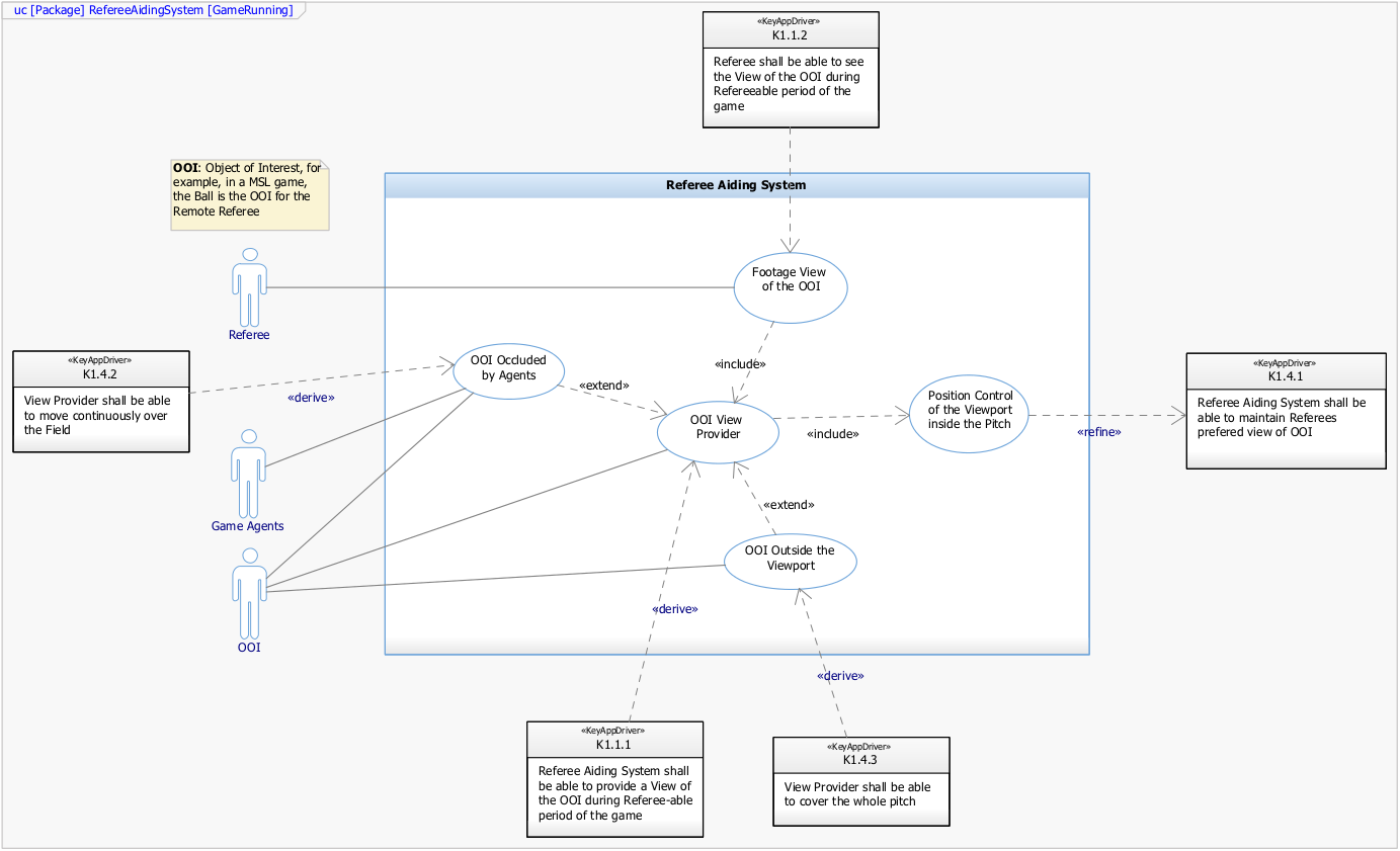
RAS use case
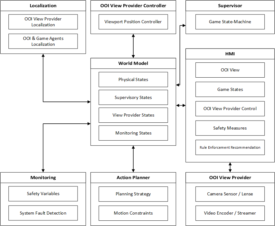
RAS context diagrams
MSL/Ball-Following 2D
MSL/Ball-Following 2D CAFCR
MSL/Ball-Following 2D use cases
MSL/Ball-Following 2D context diagrams
MSL/Ball-Following 2D Sub-Systems
Drone
World Model
Camera footage system and HMI
Supervisor
Action planner
Localization systems
MSL/Ball-Following Gimbal
MSL/Ball-Following Gimbal CAFCR
MSL/Ball-Following Gimbal use case
MSL/Ball-Following Gimbal context diagrams
Project Management
Introduction
Project management plan
Communication management plan
Quality management plan
Test management plan
Risk analysis
Simulation
Introduction
Architecture constraints
System description
Interface (I/O) descriptions
Component descriptions
- 2-D
- Gimbal
Design choices
Technology
Implementation
Drone
Introduction
The drone is the main hardware subsystem of the RAS. This subsystem includes sensors, microcontroller, communication ports and mechanical components. The drone used in this project, is the last version of Avular curiosity drone provided by Avular company. The drone can be programmed by means of Matlab Simulink. All the other subsystems must eventually be implemented on the drone to achieve the final goal of game refereeing.
Architecture constraints
*RAS:
The drone must be able to fly autonomously.
The drone is responsible to follow the command of action planner through world model
The sensors data must be accessible to world model (the other subsystem of RAS)
The drone should provide the battery level information to other subsystems.
The drone must have the possibility of installing the footage camera on it.
*Drone MSL:
The drone must be able to fly for 5+2 minutes and show the battery level all the time.
System description
The drone is the main hardware subsystem of drone referee system which consists of different components and subsystems itself. The main task of the drone is to receive commands in real time from a remote computing module (usually a PC) and follow the action required from action planner while carrying the footage camera. For this need,the main challenge is programming the drone and setting the wireless connection for sending wireless data to the microcontroller present on the drone. There are three main computation modules called “Low-Level Module”, “High-Level Module” and “Compute Module”. Each one of the Low-Level, High-Level, and Compute Modules is connected to a different set of sensors, actuators or communication devices. The idea is to use Low-Level Module for calculations related to flight stabilization and monitoring the current status of the drone, and use the High-Level Module for other high-level calculations (such as path planning or position control of the drone) which can be different depending on the project requirements. For projects that require intensive computations, the Compute Module can also be used in combination with both High-Level and Low-Level Modules. Each one of the High-Level and Low-Level Modules uses one 180MHz Cortex-M4 processor and the Compute Module is a Raspberry-Pi Compute Module 3.


