Embedded Motion Control 2013 Group 9: Difference between revisions
| Line 366: | Line 366: | ||
*''' Back-up program ''' | *''' Back-up program ''' | ||
To be sure that we at least find the exit in the maze we started with the constructing of a “simple” program were we follow either the left or right wall also known as the “follow the wall” algorithm as explained earlier. We will use this follow the wall method if we got lost in the maze and as backup if our more advanced maze solving algorithm fails to find an exit. For the follow the wall algorithm we drive Pico till an junction and turn always to the same direction if that is possible if we can’t drive in the preferred direction we drive straight ahead | To be sure that we at least find the exit in the maze we started with the constructing of a “simple” program were we follow either the left or right wall also known as the “follow the wall” algorithm as explained earlier. We will use this follow the wall method if we got lost in the maze and as backup if our more advanced maze solving algorithm fails to find an exit. For the follow the wall algorithm we drive Pico till an junction and turn always to the same direction if that is possible if we can’t drive in the preferred direction we drive straight ahead. | ||
*''' Main program ''' | *''' Main program ''' | ||
The main maze solve method which we are going to use during the final competition is somewhat based on the explore a node method as mentioned in the “Shortest path algorithm” mentioned earlier. | |||
=== Pico movement / driving=== | === Pico movement / driving=== | ||
Revision as of 13:16, 15 October 2013
Group members
| Name: | Student id: | Email: |
| Jeroen Lamers | 0771264 | j.w.lamers@student.tue.nl |
| Rens Samplonius | 0785119 | r.j.samplonius@student.tue.nl |
| Haico Ploegmakers | 0775395 | h.e.c.w.ploegmakers@student.tue.nl |
| Frank Evers | 0789890 | f.evers@student.tue.nl |
| Filipe Catarino | 0821789 | f.freire.catarino@student.tue.nl |
| Tutor: |
| Janno Lunenburg |
Planning
| Week: | Activities: | People: |
| Week 1 |
|
* Everbody |
| Week 2 |
|
|
| Week 3 |
|
|
| Week 4 |
|
|
| Week 5 |
|
|
| Week 6 |
|
|
| Week 7 |
|
|
| Week 8 |
|
|
Progress
Week 1: September 2 - September 8
The first week mainly consisted of installing the Ubuntu OS with all the required ROS/Gazebo software. This did not went smoothly as there is no easy available Ubuntu installation for Mac (1 member) and missing one tiny step in the Tutorials could end up with a not working environment.
It was decided that everyone should do all the tutorials to know how everything works, and that we would work with the software provided by the course material (QT for c++ and fuerte Ros).
Week 2: September 9 - September 15
During the second week everyone finished the tutorials for ROS and c++.
Robot Sensors
Researching the given example with the simulation environment shows that the laser data is acquired by scanning in a 270 degree angle with increments of 0.25 degrees. This information is saved in a a vector and can be used to obtain distances for every angle at a certain time.
Week 3: September 16 - September 22
The third week consisted of 2 parts:
- Creating the architecture of the system, by dividing all the necessary steps into functions.
- Focus on the corridor competition
System functions & Architecture
The group was split into two teams where 2 people where focusing on the architecture of the system. By doing this early it is clear how the system is going to be created. There is one main file that is able to call for all different functions that are required for the situation at hand. The focus of course is on the basic functions of the system for the corridor competition. These functions are:
- Driving in a straight line in the middle of the corridor
- Detecting the corner on either the left or the right side
- Turn into the corner and leave the corridor
- Stop outside the corridor
Corridor Competition concept
Because the contest dictates that the robot will be between the walls, and facing the end of the competition, the idea is that the robot is able to drive forward into the corridor. Because the robot is put there by human hand, and walls might not be exactly parallel there has to be some kind of control. By measuring the closest distance to the walls with the laser, the robot is able to calculate where the middle of the corridor is. The laser is then also used to calculate the angle between the robot and the wall.
The concept program for the corridor competition is drawn in the following schematic:
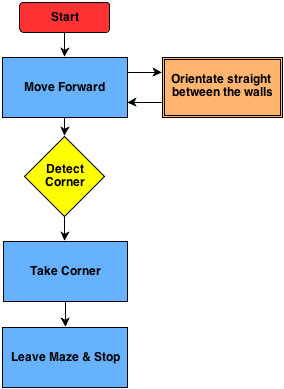
To make this program possible, the system has a main loop with a case switch. This will activate the functions that are required at that moment. When for example the corner is detected it will switch to that function.
Driving Straight: To drive straight the robot measures the closest distance to each wall and also the corresponding angle. Using this information the orientation of the robot and the position in the corridor is determined. Using a controller, the robot will drive forward and correct its position until it is moving forward in the middle of the corridor.
Corner Detection: The corner is detected by looking at an angle of 90 degrees. If there is a sudden change in that distance (opening in the wall) the system will switch to the corner function.
Turn into Corner: After detecting the corner, it will drive while keeping the corner at the same distance. After this it will drive straight until the walls disappear and stop.
Week 4: September 23 - September 29
Test on the Robot
After we created a program for the Corridor Competition, the simulation showed good results. By running the program with the robot in various positions in the Corridor we concluded that the program was functioning properly. After that came the testing on the Robot. There were a lot of problems with the Robot. For that reason we were not able to have normal testing until one day before the contest.
In the end the tests on the robot were successful. The Robot was able to drive straight trough the corridor, however due to the hysteresis, friction and the low values on the controller it drove in a stretched S-shape, like a snake. The corner however was very smooth.
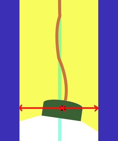
The Competition
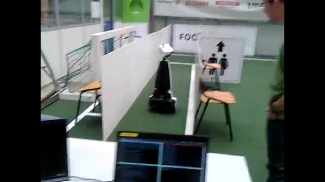
After some problems where the robot would turn after initialization, the competition was a success in the second try. Group 9 set the third time of 4 groups what were able to finish the competition.
<br\>
Strategy
After the competition and a brainstorm session we came to the conclusion that this method is only effective for straight corridors with single exits. Watching the maze that is provided with the simulation is is clear that there are a lot of different types of situations. Also decisions on where to at certain junctions is not supported by the current code. Therefor the strategy should contain 'mapping'. This way there is a way to detect the path in front of the robot while also saving everthing that was discovered before. This should prevent driving into allready explored parts.
Week 5: September 30 - October 6
This week we started with a totally new design for the pico software architecture. For the corridor competition we only focused on a particular task, driving straight and take one corner. In the real maze more functions and software features will be required. We started by separating the existing code in even more individual functions. We split our group in 3 subgroups
- Frank and Filipe look into analyzing of the laser data and come up with a matrix of “edges” from which lines can be determined.
- Rens and Jeroen will use this information to determine a trajectory through the junctions based on “nodes”.
- Haico wil look into the arrow detection with the camera.
Finding 'Hard Points'
The way to find corners is based on scanning the entire range of the laser. From the position of the robot, a corner can be detected by finding a sudden change in the distance in another direction. Using this theory, there are 2 types of corners: one where the middle is closest and the distance grows from this point (a corner to turn around), and also a corner that is opposed to this (a corner to turn before). This way the robot and drive to a junction, determine the type, and then use this information to take the specific corner.
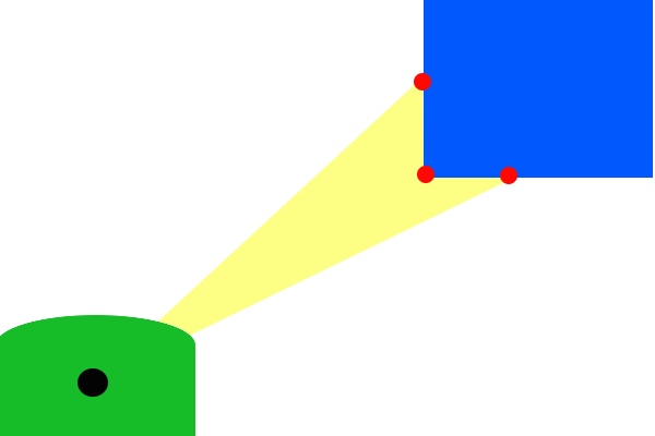
Determine Trajectory in Junctions
After the 'hard points' are known, the junction can be determined. This way we have the possibility to pick one of the directions and also drive trough it. Because there are only so many possible junctions, it is possible to prepare for all of these and determine the trajectory.
Vision
Haico looked for a solution.
Week 6: October 7 - October 13
- Determine junction type
Jeroen made a function in the c++ code to detect the type of junction when the robot is approaching one. How this has been done will be explained later.
- Arrow detection
Haico is still looking to detected arrows based on the camera data.
- Hough transformation for lines and edges
In the meantime Frank is working on the Hough transformation to detect lines and edges.
- Robot movement
Rens started with improving the way the robot turns around a corner and how to cross a cross section.
- Software architecture
Filipe has been looking on the final software architecture and stared with integrating individual functions.
- Testing on Pico
At the end of the week we booked some time on the actual robot to obtain some bag files of the camera. These bag files are used to test and tune the arrow detection algorithm. We placed an red arrow at the end of an corridor one time point to the left another time point to the right and during several drives through the corridor we recorded the camera footage.
Week 7: October 14 - October 20
- Wiki
We finally started with updating the wiki page of this group. In the PICO chapter we explain all the individual components of our software program. Jeroen will update the wiki when there is new relevant information available.
- Arrow detection
Haico finished together with Jeroen the arrow detection code to determine if we detected an arrow if it’s pointing to the left or right. This information is used in the “decision” function with the highest priority. How he designed the arrow detection will be explained later.
- Hough transformation for lines and edges
Last week Frank made a lot of progress with the Hough transformation he is able to determine lines and based on the intersections of lines he will determine edges.
- Robot movement
Rens finished the improvement of the way the robot turns around a corner and how to cross a cross section. He also made with Filipe the code for turning 180 degrees on the same spot. This is used when we are in a dead end. How we turn 90 or 180 degree is explained later. Filipe is looking into the controllers which we use to drive in the coners and try to optimize them more with PID based controllers.
- Software architecture
Each time we finish a separate function, for example this week the arrow detection function is finished, Filipe intergrades it in the final program.
Week 8: October 21 - October 27
PICO
Assignment
This course is about software design and how to apply this in the context of autonomous robots. The accompanying assignment is about applying this knowledge to a real-life robotics task in which ROS will be the standard software framework. The goal of the assignment is to get the real-time concepts in embedded software design operational.
The concrete task that has to be solved is to let the PICO robot find his way out of a maze. The final demonstration by each participating group of 4-5 students will be performed during a contest, the winner of which is the group that exits the maze in the shortest amount of time.
Some theory about solving mazes
We start with obtaining some general and basic methods of solving a maze. With these methods in mind we can perhaps determine a good solution for the maze competition in the embedded motion course.
- Follow the wall
The name already explains what this methods does, it follows a wall. It is not very difficult to program this for the pico robot. At the initial point of the maze the robot just choses either the left or right wall and will follow this wall till it find an exit or when there is no exit it will return to the starting point. For the situation where the left wall has been chosen, when the robot is at a junction it always prefers to turn left or when this is not possible it goes straight ahead. There is no need to keep track of the junctions it took in the image below we depicted an example of this method.
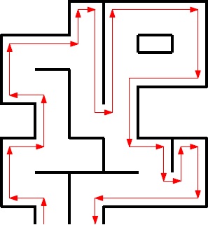
In the image above we followed the left wall and as can be observed this is not the most efficient method however it will find an exit.
- Trémaux's algorithm
Trémaux's algorithm, invented by Charles Pierre Trémaux[1], is an efficient method to find the way out of a maze that requires drawing lines on the floor to mark a path, and is guaranteed to work for all mazes that have well-defined passages. A path is either unvisited, marked once or marked twice. Every time a direction is chosen it is marked by drawing a line on the floor (from junction to junction). In the beginning a random direction is chosen (if there is more than one). On arriving at a junction that has not been visited before (no other marks), pick a random direction (and mark the path). When arriving at a marked junction and if your current path is marked only once then turn around and walk back (and mark the path a second time). If this is not the case, pick the direction with the fewest marks (and mark it, as always). When you finally reach the solution, paths marked exactly once will indicate a direct way back to the start. If there is no exit, this method will take you back to the start where all paths are marked twice. In this case each path is walked down exactly twice, once in each direction. This method is more difficult to program as the follow the wall algorithm because we need to keep track on which turns we took and how many times we visited a corridor.
[1] Public conference, December 2, 2010 - by professor Jean Pelletier-Thibert in Academie de Macon (Burgundy - France) - (Abstract published in the Annals academic, March 2011 - ISSN: 0980-6032) Charles Tremaux (° 1859 - † 1882) Ecole Polytechnique of Paris (X:1876), french engineer of the telegraph
- Shortest path algorithm
A way to solve a maze which for example contains multiple exits is a shortest path algorithm such as the breadth-first algorithm. The general idea behind a breadth-first search algorithm is that we examine a starting node, say 1. Then we examine all the neighbors of 1, then we examine all the neighbors of all the neighbors of 1, and so on.., until we reach the desired ending node or until we have no nodes to examine (in this case no path will exist). Naturally, we need to keep a track of all the nodes to assure that no node is processed more than once. This is accomplished by linking a field "status" with all the nodes. An example is shown below.
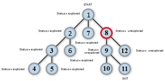
Again this method is more difficult to program as the follow the wall algorithm because we need to keep track on which node we visited.
A usefull website for more information about maze solve algorithms is: http://en.wikipedia.org/wiki/Maze_solving_algorithm
Software architecture
- ROS nodes
- C++ layout
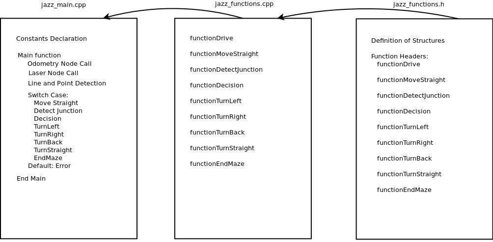
As shown above our cpp program is divided into 3 files. "jazz_main.cpp", "jazz_functions.cpp" and "jazz_functions.h". In "jazz_main.cpp" we define our global variables and constants. All our secondary functions will be called from the main function. This main function starts by calling the laser and odometry nodes. Then it starts a loop that goes through a line and point detection code. Further beggins a switch case statement where several cases are treated, each one is calling a secondary function from the file "jazz_functions.cpp". These cases can be observed in the flowchart above. The file "jazz_functions.cpp" is used as a support to place all necessary functions to the main function. In "jazz_functions.h" we declare our structures and headers of the functions used in "jazz_functions.cpp".
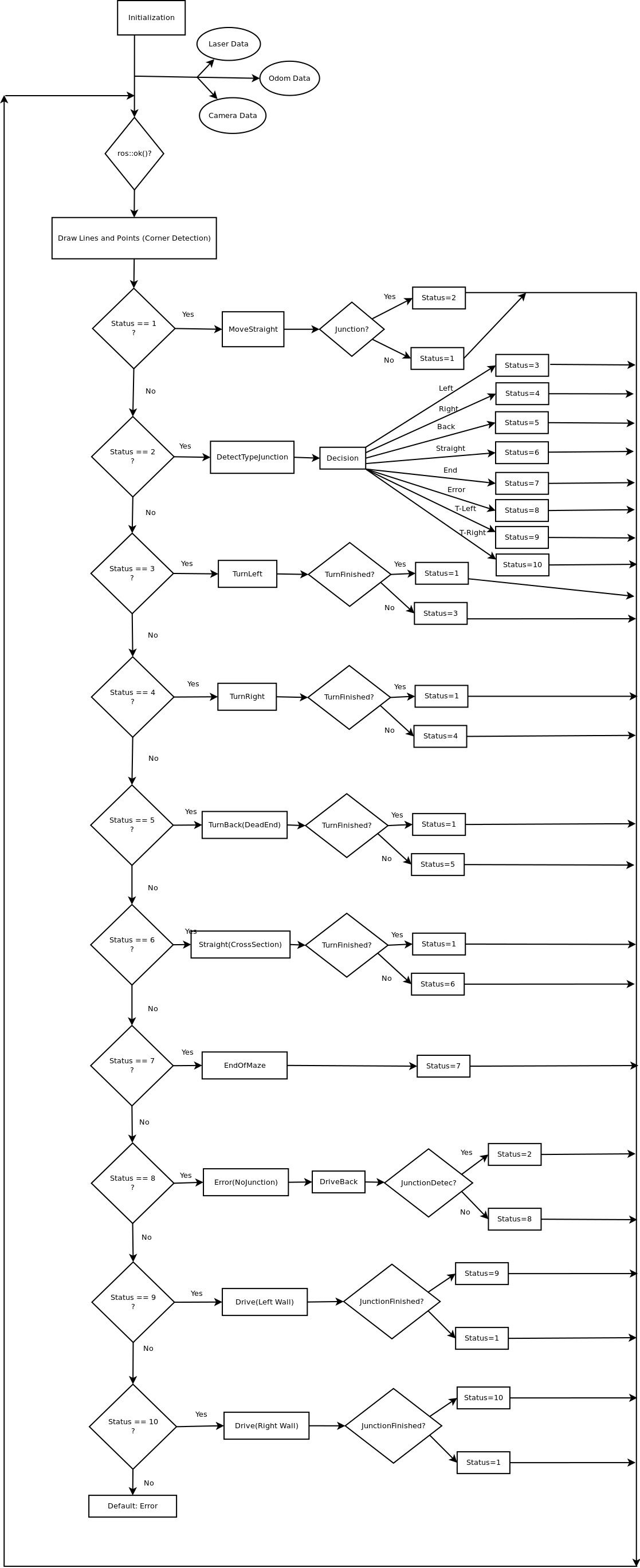
- Main program flow
The main program flow is depicted below.
Laser data interpretation and processing
- Data preprocessing
Line and edge detection using Hough algorithm
TODO
Junction detection
While driving through a corridor we keep searching for a gap on either the left side of the robot or the right side. This detection of gaps runs parallel while driving straight. At the moment we detect a gap we stop immediately and we start with the determination of the type of junction which we encountered. This is done based on the lines and edges data explained earlier. In the figure below we shown all type of junctions which our program can detect.
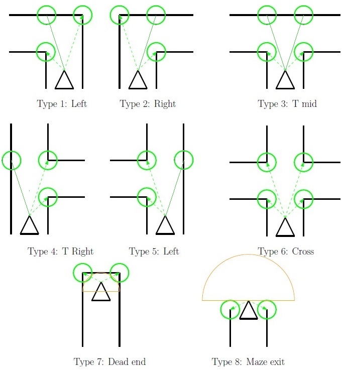
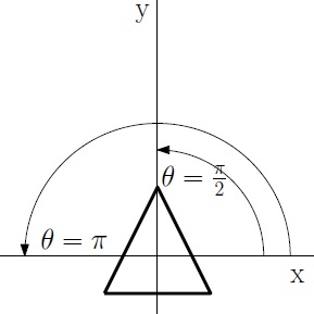
As can be observed with the green circles around the most dominant edges at a specific junction each type of junction as unique features. Based on these unique features we can determine what type of junction it is. For each time we summarize how we do this. To do that we first explain a bit how we see points on a map. We place a simple 2D grid on the center of Pico and use the standard convention of angles, meaning that an angle of 0 is a line parallel to the x axis on the right side of the robot. A line with angle of pi/2 is straight ahead etc. as shown in the figure below.
- Type 1 - Left: If we have two dominate edges and one edge is left side of the robot and one edge is on the right side and that the edge on the left side is closer that the one at the right side ( with certain margins of course) we determine it is a junction to the left.
- Type 2 - Right: The same as with left but then the otherway around. If we have two dominate edges and one edge is left side of the robot and one edge is on the right side and that the edge on the right side is closer that the one at the left side we determine it is a junction to the right.
- Type 3 - T_Mid: If we have two dominate edges where one edge is on the left and one edge is on the right side of the robot and they are approximately the same distance away from the center of the robot ( again with a certain margin ) and we don’t detect a wall in front of the robot we determine it is a T junction with left and right corners.
- Type 4 - T_Right: If we have two dominate edges and both of them are on the right side of the robot where one edge is further way as the other we determine it is a T junction where we can go straight ahead of right.
- Type 5 - T_Left: If we have two dominate edges and both of them are on the left side of the robot where one edge is further way as the other we determine it is a T junction where we can go straight ahead of left.
- Type 6 - Cross: If we have four dominate edges and two of them are on the left side and two on the right side we determine a cross section.
- Type 7 - Dead end: If we have two dominate edges where one edge is on the left and one edge is on the right side of the robot and they are approximately the same distance away from the center of the robot ( again with a certain margin ) and we detect a wall in front of the robot we determine it is a dead end.
- Type 8 - End of maze: If we have two dominate edges where one edge is on the left and one edge is on the right side of the robot and they are approximately the same distance away from the center of the robot and we don’t detect a wall nearby we found the exit of the maze.
Maze solve algorithm
In this section we explain what kind of maze solve algorithm we used in the final contest. As mentioned above we investigated several methods of solving a maze on an efficient and fast way.
- Back-up program
To be sure that we at least find the exit in the maze we started with the constructing of a “simple” program were we follow either the left or right wall also known as the “follow the wall” algorithm as explained earlier. We will use this follow the wall method if we got lost in the maze and as backup if our more advanced maze solving algorithm fails to find an exit. For the follow the wall algorithm we drive Pico till an junction and turn always to the same direction if that is possible if we can’t drive in the preferred direction we drive straight ahead.
- Main program
The main maze solve method which we are going to use during the final competition is somewhat based on the explore a node method as mentioned in the “Shortest path algorithm” mentioned earlier.
Pico movement / driving
- Moving staight
- Turning left or right
- Crossing a cross
- Dead end
Arrow detection
TODO