Retake Embedded Motion Control 2018 Nr2: Difference between revisions
| Line 115: | Line 115: | ||
== Software Architecture == | == Software Architecture == | ||
The software that will be deployed on PICO can be categorized in four different components: perception, monitoring, plan and control. They exchange information through the world model, which stores all the data. The software will have just one thread and it will execute the four components in a loop: first perception, then monitoring, plan, and control. | |||
= Implementation = | = Implementation = | ||
= Results and Conclusion = | = Results and Conclusion = | ||
Revision as of 13:12, 17 August 2018
Student
| TU/e Number | Name | |
|---|---|---|
| 1036818 | Rokesh Gajapathy | r.gajapathy@student.tue.nl |
Introduction and Problem Definition

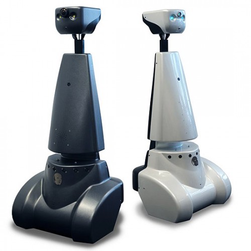
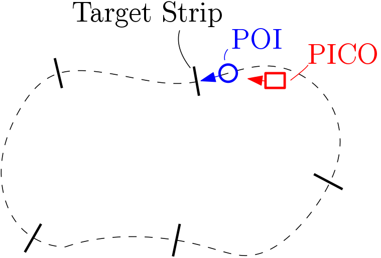
The motivation for "Follow Me!" project is to develop a software architecture for PICO to assist elderly person in carrying the objects and follow the person to the desired position. In this project, three levels are defined to achieve the goal in a robust manner. The elderly person is defined as a Person Of Interest (POI), static obstacles and actors are all part of the environment (World).
PICO must follow the POI, POI will not move at a speed more than 0.5 m/s (i.e) approximately 0.75 step/second. PICO should follow the POI at a distance of 0.4 m. The level one task was only designed, developed, implemented and tested. In level one, the PICO should follow the POI with the disturbances of actor in the environment. The actor cannot occlude the POI (i.e) should not come in between the POI and PICO.

The POI should pass through the middle of the target strips as shown in Figure 3, the number of target strips will be around 5. PICO should pass through 80 % of the target strip.

Initial Design
The initial design section gives an overview of the various design decisions taken to achieve the desired results. The requirements for completing the task with available resources is defined followed by the state machine and finally functional components required to achieve the state machine defined.
Available Resources
| Specification | Value | Unit |
|---|---|---|
| Detectable Distance | 0.01 to 10 | meters [m] |
| Scanning Angle | -2 to 2 | radians [rad] |
| Angular Resolution | 0.004004 | radians [rad] |
| Distance between POI and PICO | 0.4 | meters [m] |
| Speed of POI | 0.5 | meter/second [m/s] |
| Width of target strip | 1 | meter [m] |
Design Decisions
From the available resources and problem definition important design decisions are taken as follows:
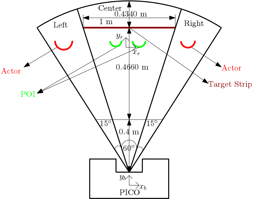
1. The maximum detectable distance and scanning angle is constrained to 1 m and 90 degree respectively because the length of the target strip is 1 m, a equilateral triangle is drawn with respect to LRF center which is 60 degree for center, 15 degrees for left and degree right respectively.
2. The reference frame [math]\displaystyle{ (x_r,y_r) }[/math] and base frame [math]\displaystyle{ (x_b,y_b) }[/math] is defined as POI and PICO respectively. Since PICO need to follow the POI (i.e) go forward or rotate with respect to the POI.
3. The PICO moves at a speed of 0.5 m/s and rotates at 2 rad/s because the POI walks at speed of 0.5 m/s.
4. Stopping distance is 0.4 m (i.e) if the distance between POI and PICO less than 0.4 m PICO stops obtained from the problem statement
5. The delectable sensor range is split into three components left,center and right to tackle the disturbances (i.e) Actors.

Requirements
| Function | Action | Validation |
|---|---|---|
| Identify the POI (reference frame) | Two legs are identified which is close to PICO (base frame) | Visualize using lase range points, see |
| Follow the POI | Follow the POI at a distance of 0.4 m at a speed of 0.5 m/s | Walk straight in-front of the PICO |
| Rotate with respect to POI | Base frame (PICO) rotates with respect to the reference frame (POI) at 2 rad/s | Walk right and left side in-front of the PICO |
| Stop when POI stops | PICO stops when the distance between POI and PICO less than 0.4 m | Stop while walking in-front of PICO |
| Stop when POI stops | PICO stops when the distance between POI and PICO less than 0.4 m | Stop while walking in-front of PICO |
| Do not follow the Actors | Scanning Angle is constrained to 60 degree and if legs are identified in the right or left side of the PICO, it follows the one in center. | Actors walk on the side of the robot not in between the PICO and POI |
Finite State Machine

Software Architecture
The software that will be deployed on PICO can be categorized in four different components: perception, monitoring, plan and control. They exchange information through the world model, which stores all the data. The software will have just one thread and it will execute the four components in a loop: first perception, then monitoring, plan, and control.