Retake Embedded Motion Control 2018 Nr3: Difference between revisions
| Line 123: | Line 123: | ||
<div><ul> | <div><ul> | ||
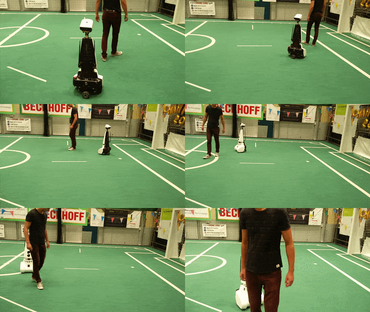
<li style="display: inline-block;"> [[File:Follow_me.gif|size=small|thumb| | <li style="display: inline-block;"> [[File:Follow_me.gif|size=small|thumb|500px|Image: 500 pixels|Follow POI]] </li> | ||
<li style="display: inline-block;"> [[File:Follow POI.png|size=small|thumb| | <li style="display: inline-block;"> [[File:Follow POI.png|size=small|thumb|650px|Image: 650 pixels|Figure 4: Flowchart: Follow POI.]] </li> | ||
</ul></div> | </ul></div> | ||
Revision as of 00:17, 17 August 2018
This wiki describes and explains the software that was made for and implemented on the PICO robot to complete the retake of Embedded Motion Control course 2017-2018. The mission of the retake EMC 2018 is describe in the subsection ‘The challenge ‘Follow me!’’.
The robot that is used during the project is PICO. PICO has a holonomic wheelbase with which it can drive, a Laser Range Finder (LRF) from which it can gather information about the environment (blocked/free space) and wheels that are equipped with encoders to provide odometry data. All software that is developed has to be tested on the robot. There is also a simulator available which provides an exact copy of PICO’s functionalities. PICO itself has an on-board computer running Ubuntu 16.04. The programming language that is used during the course and the retake is C++ and Gitlab is used to store the code.
Student
| TU/e Number | Name | |
|---|---|---|
| 1037038 | Daniël (D.J.M.) Bos | D.J.M.Bos@student.tue.nl |
The challenge ‘Follow me!’
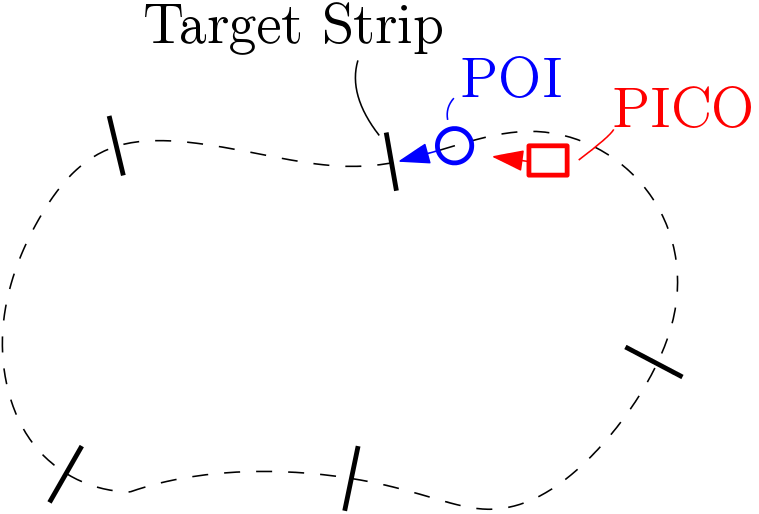
The main goal is to follow the Person Of Interest (POI) in a cluttered environment. The person closest to PICO is the POI at standstill. The POI will walk a pre-defined route that’s unknown to the PICO. There are targets strip which the POI will cross in the middle. To prove whether PICO is able to follow the POI correctly, PICO should also cross these target strips. A overview of the setup is shown on Figure 1.
The are also other actors present in the area of interest. These actors will similarly as the POI start at standstill. The other actors will also walk around when PICO has started his following-algorithm. The only restriction that the actors have is that they can never occlude the POI, i.e., they can not walk in between PICO and the POI. Figure 2 depicts a situation which can not occur.
Initial Design
Introduction:
For the initial design, the requirements will be discussed as well as the functions and their specifications. Moreover, a list of the used hardware components and the diagram of the interface are shown below.
Requirements:
- Execute all tasks autonomously.
- The POI will start initially close to and is detectable at standstill.
- Finish the challenges within 2 minutes.
- The POI will move in such manner that, in most cases, two legs are visible.
- The POI will pass trough the middle of the target strips.
- The PICO must cross 80% of the target strips.
- The PICO must follow the POI at a distance of approximately 0.4 [m].
- Perform all tasks without bumping with a person.
- Perform all tasks without getting stuck in a loop.
Specifications:
The specifications are based on the requirements.
For the POI:
- The maximum velocity is 0.5 [m/s].
For the PICO:
- The maximal transitional velocity in any direction is 0.5 [m/s].
- The maximal rotational velocity is limited to 1.2 [rad/s]
- PICO should not stand still or make no sensible movements for periods over 30 [seconds].
- The PICO must follow the POI at maximum distance of 0.4±0.2 [m].
- Finish the challenge within 2 [min.].
The targets strips:
- The width of targets strips are each 1 [m].
- The number of target strips is around 5.
Functions:
The functions that are going to be implemented are subdivided into three different types of functionality. The types are low level, middle level and high level.
- Low level: referred to as the motion functions, these functions will be used to interact directly with the robot.
- Middle level: a more abstract level, belongs to the skill functions and they perform specifics actions.
- High level: most abstract level, they are in the task functions. The task functions are structured to carry out a specific task, which consists of multiple actions.
So, in a task function, a specific order of actions will be specified in order to be able to fulfill the task. The actions that the robot can perform, and are therefore available to be called by the task functions, are specified in the skill functions. The motion functions are used in the skill functions to be able to invoke physical behavior by the robot.
Motion functions:
- Actuation: Using the actuation function PICO is given the command to drive in a specific direction or to turn in a specific direction. The input to this function is a movement vector which specifies in which direction and how far the robot should move. The output is actual robot movement according to this vector and the control effort needed for this movement.
- Obtain information: Using the obtain information function sensor readings can be requested. The input for this function is the request of a (sub)set of sensor data from a specific sensor(set), either the Laser Range Finder (LRF) or the odometry encoders.
Skill function:
Task funciton:
Components:
To be able to execute the Follow me!’ challenges the PICO robot, already mentioned above, will be used. The following hardware components will be utilized:
Actuators: holonomic base with three omni-wheels.
Sensors:
- Laser range finder (LRF): To detect the distances to objects in the environment.
- Range: To be determined.
- Field of view: 270 degrees.
- Accuracy: To be determined.
Computer: running Ubuntu 16.04.
Software explanation
The software is subdivided in two main parts, Find POI, POI following algorithm. They are described below.
Find POI
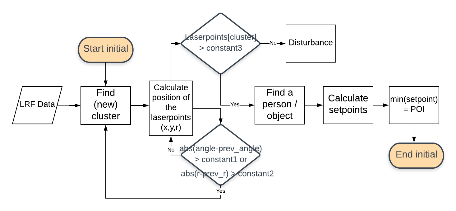
First PICO has to find POI. The structure of the software of these classes is shown in Figure 3. With the LRF data is it possible to find something, i.e, a person, a objects, a wall or disturbance. The LRF data is split into clusters. A cluster is a series of laser points, which are connected to each other. Afterwards it must be determined whether the cluster is, the POI, a person/object/wall or disturbance.
Clusters can be found with threshold filters for the angle and radius between laser points. If de angle between laserpoints are larger than constant1 or/and the distance between laser points are larger then constant2 then a new cluster is found. If a cluster is larger than constant3 then a person, object or wall is found otherwise it is disturbance. Then the setpoints must be calculated, the person with the setpoint that have the smallest distance between the setpoint and PICO is the POI.
Note: At the start there is a person nearest PICO not something else.

POI following algorithm (one person on the field)
The next step, after that POI is found, POI has to be followed by PICO. During the test session is tested first with one person on the field. That person is then POI that must be followed and PICO can not accidentally follow other persons. Int = 0 at the intial part and int = 1 at the following part, the flowchart Follow POI is shown in Figure 4.
POI following algorithm (with other persons on the field)
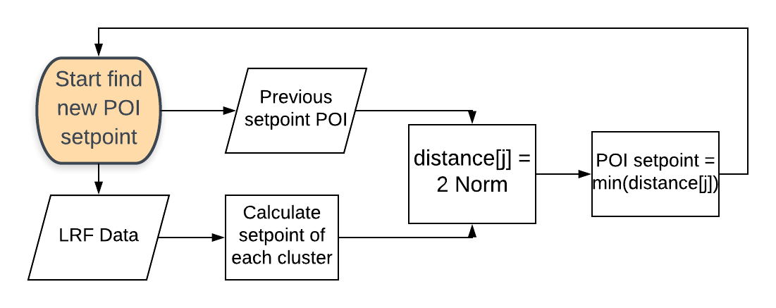
The following algorithm that is used for follow POI with other persons on the field is 'Nearest neighbour'. The idea is to compare the distance between previous setpoint of the POI and the new clusters setpoints (new laser scan), the smallest distance between previous POI setpoint and one of the cluster setpoints is the current POI cluster. The 2-norm calculation for the distance between previous setpoint and the current clusters is below. The flowchart 'find new POI setpoint' is shown in figure 5.
[math]\displaystyle{ \text{distance}[j] =\sqrt{(pos_xPOI-pos_x[j])^2-(pos_yPOI-pos_y[j])^2} \text{ where, j is the number of the current cluster.} }[/math]
[math]\displaystyle{ \text{POI} = min(\text{distance}[j]) }[/math]


